
A Control Method for Switching-Type Frequency Oscillations in
Hydropower System Based on Adjusting Dead Zone Structure
Hongtao Xiong
1
, Boxiong Zhang
1
, Boliang Lou
1
, Xiaobo Liu
2
,
Shan Hou
2
, Jiawei Wang
2
and Ancheng Xue
2,*
1
Zhejiang Electric Power Research Institute, Hangzhou, Zhejiang 310014, China
2
State Key Laboratory of Alternate Electrical Power System with Renewable Energy Sources (North China Electric Power
University), Changping District, Beijing 102206, China
Keywords: Enhanced Dead Zone, Hydropower System, Switching-Type Frequency Oscillation, Control Method.
Abstract: For the switching-type ultra-low frequency oscillation (ST-ULFO) that cannot be suppressed by increasing
damping, in the single-hydropower-generator power system (SHG-PS) with enhanced dead zone, a control
method based on adjusting the non-smooth structure of the dead zone is proposed. First, the model of the
SHG-PS with enhanced dead zone, corresponding to Filippov non-smooth system, and the ST-ULFO
phenomenon are introduced. Second, a case of oscillation cannot be suppressed by increasing system
damping, as the system equilibrium point disappeared under disturbance, is introduced. Next, a construction
method to make the enhanced dead zone continuous is given. Then, the Hopf-like non-smooth bifurcation
characteristics of the equilibrium point and the post fault dynamics of the SHG-PS before/after the enhanced
dead zone continuity are compared. Finally, the effectiveness of control method is verified in the SHG-PS
and the 2-area-4-generators system. The results show that, the oscillations which cannot be suppressed by
increasing system damping, will be effectively suppressed by adjusting the enhanced dead zone structure.
1 INTRODUCTION
Ultra-low frequency oscillations (ULFOs) have
occurred many times in the power grid with a high
proportion of hydropower at home and abroad (Li et
al., 2018). The ULFOs are quite different from the
traditional low-frequency oscillations and threaten the
safe operation of the power system Xue et al., 2021).
The ULFOs are mainly explained by the negative
damping oscillation (Liu et al., 2016), the smooth
forced oscillation (Ju et al., 2014), or the switching-
type oscillation (non-smooth oscillation)
Xue et al.,
2021). The negative damping oscillation and the
smooth forced oscillation correspond to the
oscillations in smooth dynamical systems. While the
switching-type oscillation correspond to the
oscillations associated with the switches, such as dead
zones, limits, or control switches in the non-smooth
dynamical system (Xue and Wang, 2020)(Xue et al.,
2021).
The negative damping oscillations and smooth
*
Corresponding author
forced oscillations can be suppressed or prevented by
increasing the system damping. Due to the influence
of water hammer effect, hydropower generators
exhibit negative damping characteristics in the ultra-
low frequency band. Thus, the control measures for
ULFOs also adopt the way of improving system
damping, such as optimizing the PID parameters of the
governor (Zhou et al., 2017).
It is worth noting that, although the control
measure of improving system damping has good
universality, the switching-type oscillations reflect the
large-scale dynamics of the system and have no clear
correspondence with the local properties of the
equilibrium point. For example, in a single-
hydropower-generator power system (SHG-PS) with
enhanced dead zone, the switching-type oscillations
occur when the system with no equilibrium point or
with a stable equilibrium point (SEP)
(Xue et al., 2021).
On the other hand, in addition to increasing system
damping, changing the size of dead zone can also
suppress the switching-type oscillations. For example,
Xiong, H., Zhang, B., Lou, B., Liu, X., Hou, S., Wang, J. and Xue, A.
A Control Method for Switching-Type Frequency Oscillations in Hydropower System Based on Adjusting Dead Zone Structure.
DOI: 10.5220/0012004400003612
In Proceedings of the 3rd International Symposium on Automation, Information and Computing (ISAIC 2022), pages 633-638
ISBN: 978-989-758-622-4; ISSN: 2975-9463
Copyright
c
2023 by SCITEPRESS – Science and Technology Publications, Lda. Under CC license (CC BY-NC-ND 4.0)
633

literature (Xue et al., 2021) points out that increasing
the size of dead zone of hydropower generators can
keep the system from non-smooth bifurcation and
avoid the switching-type oscillations. Although setting
a large dead zone of governor is beneficial to the
system stability, it also wastes part of frequency
regulation capability at the same time.
In summary, for the control of switching-type
frequency oscillations, increasing system damping
may be ineffective and adjusting the dead zone size
has the disadvantage of wasting the frequency
regulation capability. In view of this, aiming at the
switching-type oscillation cannot be suppressed by
increasing system damping in the SHG-PS with
enhanced dead zone, this paper proposes a control
method based on adjusting the dead zone structure,
and verifies the control effect in the SHG-PS and 2-
area-4-generators systems.
2 SYSTEM MODEL AND
OSCILLATION PHENOMENA
This section presents the system model of the
simplified single-hydropower-generator power system
(SHG-PS) with enhanced dead zone, together with its
switching-type oscillation phenomena.
2.1 System Model
The system model studied in this paper is a simplified
SHG-PS with enhanced dead zone. Its corresponding
mathematical description is as follows (Xue et al.,
2021):
14prefP41I
2P412P1y
323P1WP412y W
43L4ref LJ
[( ) ( ( ) )]
(() ) /
[(())/]2/
[( )]/
xFx bY KFx xK
xKFxxxKT
x
xxKTKFx xxT T
xxKx PT
ω
=+− −⋅
=+−⋅
=−− +− ⋅
=− − −
(1)
Where x
4
represents the angular frequency ω, and
the remaining parameters are given in the literature
(Xue and Wang, 2020). The values of the relevant
variables, if not otherwise specified, are the
standardized values. F(x
4
) is the description of the
enhanced dead zone, as shown in Figure 1.
ε
ε
−
area
A
area Barea C
4
()Fx
ref 4
x
ω
−
Figure 1: The model of enhanced dead zone.
The mathematical description is:
(2)
Figure 1 and equation (2) show that the SHG-PS is
divided into three areas by the dead zone switching
manifolds, i.e., Σ
b1
={x
4
|x
4
=ω
ref
-ε} and
Σ
b2
={x
4
|x
4
=ω
ref
+ε}. The area A/C corresponds to the
regulation area and area B corresponds to the dead
zone area. Due to the step control logic at the
switching manifolds, the system vector field is
discontinuous, thus, the SHG-PS with enhanced dead
zone is a Filippov non-smooth system (Simpson,
2018).
2.2 Oscillation Phenomena
The SHG-PS with enhanced dead zone may occur
ULFOs under sudden load perturbations (Xue et al.,
2021).
For example, when the post-disturbance load P
L
=1.02, the system has no equilibrium point and an
ULFO of 0.084 Hz occurs, as shown in Figure 2.
0 100 200 300 400
t/s
-4
-2
0
2
4
6
8
Frequency
deviation/(×10
-
3
)
switching manifold b
1
area A
area B
area C
switching manifold b
2
Figure 2: The frequency oscillation when P
L
=1.02.
Figure 2 shows that the oscillation trajectory will
cross the switching manifold Σ
b2
and change in the
area B and area C, corresponding to the switching-type
non-smooth oscillation.
ref 4
4
ref 4 ref 4
0||
()
||
x
Fx
xx
ωε
ωωε
−<
=
−−>
ISAIC 2022 - International Symposium on Automation, Information and Computing
634
3 THE CASE OF OSCILLATION
CANNOT BE SUPPRESSED BY
INCREASING DAMPING
This section represents the case that increasing system
damping cannot suppress the switching-type
oscillation and analyzes the reasons.
Increasing system damping is generally considered
as a method to suppress oscillation. For the SHG-PS
of Section 2.1, the PI control parameters, i.e., K
P
and
K
I
, can be adjusted to increase the mechanical
damping coefficient D
m
(Liu et al., 2016).
In the case of Section 2.2, the mechanical damping
coefficient D
m
under different parameter groups are
shown in Table 1.
Table 1: The damping under different parameters.
K
p
K
I
D
m
initial parameters 5 1 -2.97
parameter group 1 3 1 -2.81
parameter group 2 1 0.25 -0.78
Table 1 shows that, after adjusting PI parameters,
the system damping is improved. Under the load
disturbance of Section 2.2, the frequency changes of
systems with different PI parameters are shown in
Figure 3.
0 50 100 150 200 250 300 350 400
t /s
0.993
0.994
0.995
0.996
0.997
0.998
0.999
1
1.001
1.002
1.003
K
p
=5,K
I
=1
K
p
=3,K
I
=1 K
p
=1,K
I
=0.25
Frequency(p.u.)
Figure 3: The frequency changes under different PI.
Figure 3 shows that after increasing the damping,
the system still occur the switching-type frequency
oscillation, that is, the switching-type oscillation of
SHG-PS with enhanced dead zone cannot be
effectively suppressed by increasing damping.
It is worth noting that, although the system
damping is improved, the step characteristic at the
switching manifold of SHG-PS has not changed.
Under a certain load disturbance, the system still has
no equilibrium point, and the switching-type
oscillation will still occur. Therefore, the switching-
type oscillation of SHG-PS with enhanced dead zone
(Filippov non-smooth system) may not be suppressed
by increasing damping.
4 CONTINUOUS ENHANCED
DEAD ZONE
This section introduces a construction method to make
the enhanced dead zone continuous at the switching
manifold, so that the system has a SEP under certain
load disturbances.
To make the system always has an equilibrium
point, the dead zone characteristic should be
continuous. On the other hand, to make the governor
adjust quickly, the step characteristic shall be retained
at the switching manifold. The continuous function f(x)
simulating step characteristics, as shown in equation
(3), can meet these requirements.
()
()
1
xac
b
k
fx
e
−
−
=
+
(3)
where a, b, c, and k are the constants, determining
the interval and degree of the step.
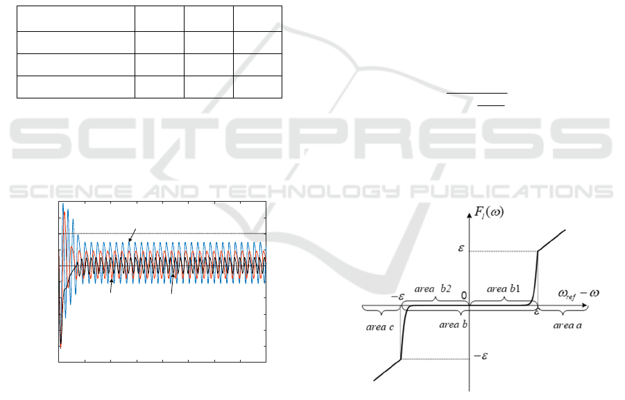
With the function f(x), the enhanced dead zone can
be continuous, as shown in Figure 4.
Figure 4: The continuous enhanced dead zone.
The mathematical description is:
A Control Method for Switching-Type Frequency Oscillations in Hydropower System Based on Adjusting Dead Zone Structure
635

()
()
0
1
0
()
1
||
ref
ref
ref
c
b
ref
c
l
b
ref ref
k
e
k
F
e
ωωε
ωω ε
ωωε
εω ω
ω
ωω ωωε
−−
−
−−
−
<−<
+
−−<−<
=
+
−−>
(4)
The SHG-PS with continuous enhanced dead zone
is no longer a Filippov non-smooth system with
discontinuous vector fields, but a piecewise-smooth
continuous system (a type of the non-smooth system)
(Simpson, 2018). That is, the type of non-smooth
systems is changed. The continuous system includes
area a, area b1, area b2 and area c.
5 SYSTEM BIFURCATION
CHARACTERISTICS BEFORE
AND AFTER CONTINUITY
This section presents the non-smooth bifurcation
characteristics of the equilibrium point and the post
fault dynamics of the SHG-PS before/after the
enhanced dead zone continued.
Considering typical system parameters, the pre-
fault system load is rated 1 and the system operates at
the SEP, i.e., (x
1
, x
2
, x
3
, x
4
) = (1, 1, 1, 1). Considering
the sudden load change (i.e., the load parameter P
L
takes different values after the perturbation), the non-
smooth bifurcation characteristics of the equilibrium
point and the post fault dynamics of the SHG-PS
before the enhanced dead zone continued can be
obtained, as shown in Figure 5 (Xue et al., 2021).
Figure 5:The non-smooth bifurcation characteristics before
continuity.
Figure 5 shows that with the change of the load
parameters, the system undergoes a Hopf-like non-
smooth bifurcation, manifesting that the equilibrium
point disappears and switching-type oscillation occurs
at the same time. Furthermore, P
2
and P
3
are the
bifurcation points (P
1
and P
4
correspond to another
type of bifurcation (Xue et al., 2021), which is not
considered in this paper).
Considering the continuous enhanced dead zone
parameters taken as: b=0.01, c=70, k=2, and ε=0.002,
respectively, and under the same simulation conditions,
the Hopf-like non-smooth bifurcation characteristics
of the SHG-PS after the enhanced dead zone continued
can be obtained, as shown in Figure 6.
Figure 6:The non-smooth bifurcation characteristics after
continuity.
Compared with Figure 5, Figure 6 shows that:
1) The range of disturbance load parameters that
may induce switching-type oscillation is decreased
after the enhanced dead zone is continuous, which is
beneficial to the system stability. For example, the
range 1.0015≤P
L
≤1.16 can be reduced to
1.007≤P
L
≤1.12, specifically.
2) After the enhanced dead zone is continuous, the
SHG-PS always has a SEP, and the switching-type
oscillation is no longer related to the system without
equilibrium point. That is, the Hopf-like non-smooth
bifurcation with the equilibrium point disappearing
does not occur, thus avoiding the switching-type
oscillations.
6 CONTROLLER
VERIFICATION
This section verifies the control effect of continuous
enhanced dead zone in SHG-PS and 2-area-4-
generators system, respectively.
6.1 Effect in SHG-PS
After the enhanced dead zone continuity, there is
always a SEP. In addition, optimizing PI control
parameters to increase damping can further increase
the global stability of system.
Taking the load perturbation parameter P
L
=1.02 as
an example, the dynamic characteristics of the SHG-
PS with enhanced dead zone and with continuous
enhanced dead zone under different PI parameters can
be obtained, as shown in Figure 7.
ISAIC 2022 - International Symposium on Automation, Information and Computing
636

Figure 7: Control effect in SHG-PS.
Figure 7 shows that:
1) With the initial parameters, i.e., K
P
=5 and K
I
=1,
the oscillation amplitude will be somewhat reduced
after the enhanced dead zone continuity. The possible
reason is that after the enhanced dead zone continuity,
the governor has begun to participate in the regulation
when the frequency deviation gradually approaches
the set value of dead zone.
2) With the optimized parameters, i.e., K
P
=1 and
K
I
=0.25, the frequency of the SHG-PS with
continuous enhanced dead zone, will return to stability.
While the SHG-PS with enhanced dead zone still
occur frequency oscillation, as shown in Figure 3. The
switching-type frequency oscillation of the SHG-PS is
effectively suppressed by adjusting dead zone
structure and optimizing PI control parameters.
6.2 Effect in 2-area-4-generators System
In this subsection, a 2-area-4-generators system, as
shown in Figure 8, is used to verify the control effect.
Figure 8: The 2-area-4-generators system.
The 2-area-4-generators system is set as follows:
four generators are all hydropower units, where the
dead zone of G1 governor is enhanced or continuous
enhanced dead zone, and the dead zones of remaining
three generators are traditional dead zone.
The main system parameters are set as follows:
dead zone
0.05Hz
ε
=
; water hammer effect
coefficient T
w
=0.3; PI parameters K
p
=5 and K
I
=2.5.
Two fault conditions are set as follows:
1) Small disturbance: 5MW load is reduced at bus
7.
2) Large disturbance: 100MW output is reduced in
generator G1.
Under large/small disturbances, the frequency
characteristics of the system with enhanced dead zone
or continuous enhanced dead zone, are shown in
Figure 9 and Figure 10, respectively.
Figure 9: The system frequency under small disturbance.
Figure 10: The system frequency under large disturbance.
Figure 9 and Figure 10 show that:
1) When the dead zone of G1 governor is enhanced
dead zone, the system will occur the oscillation with
oscillation frequency of 0.09Hz under small
disturbance. While the dead zone is replaced with a
continuous enhanced dead zone, the system frequency
gradually stabilizes and the oscillation disappears.
2) Under the large disturbance, the 2-area-4-
generators system will occur ULFO, no matter the
enhanced dead zone is discontinuous or continuous.
However, the system with continuous enhanced dead
zone has smaller oscillation amplitude, which may
reduce the degree of harm to the system.
Therefore, under large/small disturbances, the
A Control Method for Switching-Type Frequency Oscillations in Hydropower System Based on Adjusting Dead Zone Structure
637

governor with continuous enhanced dead zone can
effectively suppress the oscillation, and the system
stability is better.
ACKNOWLEDGMENTS
This work is supported by the project of "Research on
the optimization technology of coordinated control of
differentiated grid sources based on transient response
under the background of large power reception" by the
State Grid Zhejiang Province Electric Power
Company Science and Technology
(No.5211DS200086).
7 CONCLUSIONS
Aiming at the ST-ULFO in hydropower systems with
enhanced dead zone, this paper provides a control
method based on adjusting the non-smooth structure
of the enhanced dead zone and verifies its
effectiveness. The conclusions are as follows:
a) SHG-PS with enhanced dead zone is a Filippov
non-smooth system. It may have no equilibrium point
and occur the switching-type oscillation under certain
load disturbance. Only increasing the system damping
cannot suppress the switching-type oscillation.
b) The continuous function simulating step
characteristics can make the enhanced dead zone
continuous. The corresponding continuous system
maintains the rapidity of governor action, and there is
no longer a Hopf-like non-smooth bifurcation with the
equilibrium point disappearing.
c) The continuous enhanced dead zone can
effectively suppress frequency oscillation, that is,
adjusting the dead zone non-smooth structure can
suppress the switching-type oscillation.
It is worth noting that, the continuous enhanced
dead zone is an ideal model that has not yet been put
into use in real systems. To be practical, its structural
parameters still need to be optimized and analyzed.
REFERENCES
LI Wei , XIAO Xiangning , TAO Shun , et al . Frequency
stability control for islanded UHVDC sending end
system[J] . Electric Power Automation Equipment ,
2018 , 38(11) : 197 – 203 .
Xue Ancheng , Wang Jiawei , Liu Xiaobo , et al . Survey
and prospect of ultra-low frequency oscillation
mechanism analysis and suppression in power system .
Proceedings of the CSEE , 1-16 , 2021 .
Liu Chunxiao , zhang Junfeng , Chenyiping , et al .
Mechanism analysis and simulation on ultra-low
frequency oscillation of Yunnan power grid in
asynchronous interconnection mode[J] . Southern Power
System Technology , 2016 , 10(07) : 29-34 .
JU Ping , LIU Yongfei , WANG Hongyin , et al . General
forced oscillations of power systems[J] . Electric Power
Automation Equipment , 2014 , 34(5) : 1-6 .
Xue Ancheng , Wang Jiawei . Mechanism analysis of ultra-
low frequency oscillation of single hydropower system
based on non-smooth bifurcation[J] . Transactions of
China Electrotechnical Society , 2020 , 35(07) : 1489-
1497 .
Xue Ancheng , Wang Jiawei , Liu Xiaobo . Influence of the
enhanced dead zone on the non-smooth bifurcation of
ultra-low frequency oscillations in single machine
simplified systems[J/OL] . Proceedings of the CSEE ,
2021 .
Zhou Jinghao , Jiang Chongxi , Gan Deqiang,et al . Stability
Analysis of Ultra-Low Frequency Oscillation of Yunnan
Power GridBased on Value Set Approach[J] . Power
System Technology , 2017 , 41(10) : 3147-3152 .
Simpson D J W . A compendium of Hopf-like bifurcations
in piecewise-smooth dynamical systems[J] . Physics
Letters A , 2018 , 382(35) : 2439-2444.
ISAIC 2022 - International Symposium on Automation, Information and Computing
638
