
Experimental Study of Single Action System Compacting Tool in
Sealface Formation with Undercut
Josephine Sambira Pramestari
Design Engineering, Politeknik Manufaktur Bandung, Jalan Kanayakan No.21, Bandung, Indonesia
Keywords: Compacting Tool, Powder Metallurgy, Sealface, Single-Action Tooling System.
Abstract: The sealface is one of the important components in the mechanical seal which functions to prevent leakage
by utilizing two flat surfaces that rub against each other. In general, sealfaces are made through a machining
process (material removal). However, one of the studies conducted a study on the formation of face seals with
powder metallurgy technology seeking to maximize the use of raw materials. This research uses a press
machine and a tool that works with a single action system compacting tool mechanism and produces powder
metallurgical products with a simple sealface ring seal faced is classified into metallurgical products class 1
and 2. Seeing this, the authors try to use existing machines and tools to carry out an experimental study of
single action system compacting tools in the manufacture of powder metallurgical products with class 3 and
4 classifications. This research produces sealface with undercuts (finished product) that have surface hardness
and density values of 541.8 HV and 2.7 gr/mm3, as well as tool design recommendations that can correct the
deficiencies that occur in this research.
1 INTRODUCTION
A mechanical seal is a mechanical device whose
function is to prevent fluid from leaking from a
space/container with a rotating shaft (Kurniawan,
Yudianto, 2014). Mechanical seals have a low
leakage rate when compared to other types of sealing
devices, and have a longer duration of use (Syafi’i,
Priangkoso, 2018). The working principle of the
mechanical seal is to use the sealing surface as the
main point to prevent leakage (primary seal) (Wijaya,
2018). The location of the sealing surface on the
mechanical seal is shown in Figure 1.
Seal faces are generally made through a machining
(material removal) process. However, in one of the
studies at Polman Bandung, a study was conducted on
seal face formation with powder metallurgy
technology (Fachrul Rozy, Kurniawan). The purpose
of this study is to strive for the use of raw materials to
be maximized because, with this technology, raw
material savings can be made up to 97% (Groover,
2010). In addition, sealface for seal face withh this
method is also a component substitution step which
was originallymade with the usual material removal
manufacturing process to become an additive
manufacturing. Figure 2. Is a sealface ring formed by
powder metallurgy technology.
In the research process, powder metallurgy
products classified into classes 1 and 2 were made
with a simple sealface ring shape. The manufacture of
sealfaces utilizes a press machine and compacting
tools that are already available with a single action
tooling system mechanism (one-way compaction).
Seeing this, the author tries to conduct an
experimental study and utilize the available facilities
to make powder metallurgical products with a higher
classification class (class 3 or class 4). This is
intended to see whether existing machines and tools
can be utilized to produce more varied products. The
form that the author takes is a seal face with a simple
undercut.
Figure 1: Seal face components on mechanical seal. Source:
PT Aldea Citta Sejahtera.
870
Pramestari, J.
Experimental Study of Single Action System Compacting Tool in Sealface Formation with Undercut.
DOI: 10.5220/0011904700003575
In Proceedings of the 5th International Conference on Applied Science and Technology on Engineering Science (iCAST-ES 2022), pages 870-878
ISBN: 978-989-758-619-4; ISSN: 2975-8246
Copyright © 2023 by SCITEPRESS – Science and Technology Publications, Lda. Under CC license (CC BY-NC-ND 4.0)

Figure 2: Finished product sealface ring formed by powder
metallurgy technology (Fachrul Rozy, Kurniawan).
2 LITERATURE REVIEW
2.1 Mechanical Seal
A mechanical seal is a mechanical device that
prevents fluid leakage from a space/container with a
rotating shaft. Mechanical seals prevent leakage by
utilizing the contact of two flat surfaces (sealing
faces), namely the stationary unit and the rotary unit.
The two surfaces are in a sealing contact condition,
due to the influence of the spring and the pressure
from the system. Some of the advantages obtained by
using a mechanical seal as a sealing device are that it
can handle all types of fluids, can work even if
misalignment occurs, can work both dynamically and
statically with shaft rotation, and has a long lifetime.
In the mechanical seal there are 3 leakage
containment points, namely:
a. Primary seal, the point of containment of
leakage occurs in the sealing faces, namely the
primary ring and the mating ring
b. Secondary seal, leakage containment point on
the inner diameter of the primary ring
c. Tertiary Seal, leakage containment point on
the outer diameter of the mating ring
The working principle of a mechanical seal in
general is to utilize two very flat and smooth surfaces
(sealface) of two componentseal facey the primary
ring and the mating ring which are in a sealing contact
condition. This condition is achieved so that there is
a minimum but thick enough fluid film between the
two surfaces (Flitney, 2007). Fluid film that acts as a
cushion, serves to lubricate and cool the contact area
2.2 Powder Metallurgy
Powder metallurgy technology is a way of processing
metal where the product is made of metal powder
material. The product is pressed to the desired shape
and then heated to bind the powder particles into a
solid and strong mass (Groover, 2010). There basic
stages in the conventional metallurgical process are
the mixing/blending stage, the compacting/
compacting stage, and the sintering stage Figure 3.
Powder metallurgy technology is a way of
processing metal where the product is made of metal
powder material. The product is pressed to the desired
shape and then heated to bind the powder particles
into a solid and strong mass (Groover, 2010). There
are three basic stages in the con Three basic stages in
the conventional metallurgical process are the ending
stage, the compacting/compacting stage, and the
sintering stage. Figure 3.
Figure 3: Powder metallurgical processes in general
(Kalpakjian, Schmid, 2009).
a. The mixing process is a process of
homogenizing metal powder materials to
become metal alloys that can be used as basic
materials in the solidification stage. At this
stage, the metal powder is mixed with a binder
(binder) and a lubricant (lubricant) based on
both metal and non-metal.
b. The compaction process is the process of
compressing metal alloys into a formation.
c. The sintering process is a process of heating
the solidification (green compact) in a
controlled furnace with a temperature below
the melting point, in order to form a bond
(fusion) of the particles. The goal is to increase
the strength and hardness of the product.
In powder metallurgy technology, the formed
products are classified according to the
complexity of the compaction process (Groover,
2010). The following are the four classes that have
been defined, which can be seen in Figure 4.
Figure 4: Powder metallurgical technology product
classification (Groover, 2010).
• Class I, products with a simple shape and a fairly
Experimental Study of Single Action System Compacting Tool in Sealface Formation with Undercut
871

thin thickness. The compaction process for this
product can be carried out from one side.
• Class II, products with simple shapes but thick
enough. So the compaction process must be
done from two sides.
• Class III, products that have two thickness levels
and the compaction process needs to be carried
out from two sides.
• Class IV, products that have several thickness
levels and the compaction process is carried out
from two sides using separate control settings so
that each density of each level can be achieved
properly.
2.3 Tooling System
In the powder compaction process, there are four tool
systems that can be used (ASM Handbook
Committee, 2015) namely: single-action tooling
system, double-action tooling system, withdrawal
tooling system, and die floating tooling system.
2.4 Specimen Testing
2.4.1 Hardness Test
Vickers hardness (HV) is a quotient obtained by
dividing the applied load F (kgf) by the expanse area
on the indentation surface (mm
2
) of the workpiece
taking into account the pyramidal shape with a square
base and diagonal d and having the same peak angle
as indenter of gem (ASM Handbook Committee,
2015). For the Vickers test, the surface of the test
specimen should be flat and smooth in order to obtain
accurate test results. The test specimen used in the
Vickers hardness test shall not be less than 5 times the
size of the indenter. Vickers hardness number can be
obtained using the following equation:
𝐻𝑉 1.854 P/d
2
(1)
P: given load (N)
d: the average diagonal length of the results
2.4.2 Density Test
Density is a measurement of the mass per unit volume
of an object. The higher the density (density) of an
object, the greater the mass of each volume. In this
test, the Archimedes principle is applied to determine
the density of the sample by weighing the sample in
air and then in a floating liquid (usually distilled
water). Then this density is compared with the
theoretical density (Torosyan, Pak, 2019).
Actual Density
𝑚
𝑚𝑠
𝑚𝑠 𝑚𝑔
𝑥
𝐻20
(2)
𝑚 : actual density (gram/cm
3
)
ms : dry sample mass (gram)
mg : mass of sample suspended in water (gram)
𝐻20 : density of water (1 gram/cm
3
)
Theoritical Density
𝑡ℎ
𝑆𝑖𝐶 . 𝑉𝑆𝑖𝐶
(3)
𝑡ℎ: theoretical density
𝑆𝑖𝐶: SiC density
VSiC: SiC mass fraction
3 EXPERIMENTAL METHOD
This research is divided into two stages, namely the
tool modification stage and the experimental stage
which can be seen in flowchart below.
Figure 5: Flowchart of this research.
Tool modification is intended to adjust existing
tools in order to form the desired product. The
modification process is carried out to a minimum and
as efficiently as possible. The goal is that there are not
a lot of processing processes and new parts are made,
so that it can save time and work costs. At the
experimental stage, there are two processes that need
to be carried out, namely the implementation of
sealface formation with undercuts using powder
metallurgy technology and testing of the results of
making sealfaces.
iCAST-ES 2022 - International Conference on Applied Science and Technology on Engineering Science
872

3.1 Modification Step
3.1.1 Product Design
The shape of the sealface to be made is a sealface with
an undercut. This shape takes reference from the ISO
3601 O-Ring sizing standard and uses some of the
built-in dimensions of the tool. Working drawings
can be seen in Figure 6.
Figure 6: Product design for sealface with undercut. Where,
D: 56 mm, W: 4mm, H: 1.5mm.
3.1.2 Tool Existing Analysis
After determining the shape of the product, a tool
analysis is carried out to find out the specifications of
the tools and parts that play a direct role in the
formation of the product. The following is a
description of the existing tool specifications which
can be seen in Table 1.
Table 1: Existing Tool Specifications.
No.
Specifica
tion
Information
1.
N
ame Compactin
g
Tool
2. Material
St.37 and HMD 5
HMD 5: Product-forming
active parts
St.37: Other parts that are not
in contact with the produc
t
3. Dimension 208 X 239 X 248 m
m
4. Weight
± 18 Kg
5. Type
Single-action tooling system
The compaction carried out
during the compaction process
is only carried out from one
direction, namely from the
top.
In Figure 7 it can be seen that the construction of the
active part forming the product on the existing
compacting tool.
Figure 7: Active part layout.
Table 2 describes the function of each active part.
Table 2: Product-forming active parts.
No.
Compon
ent
Name
Function
Other
Information
1. Punch
Plays a role
during the
compaction
process,
pressing
metal powder
from the top.
Dimension: 70
X 70 X 70
Material: HMD
5
Further
process:
Hardening (50-
55 HRC)
2.
Insert
Outer Dies
Product
mold,
forming the
outer
diameter of
the product
Dimesion:
Ø120 X 30
Material: HMD
5
Further
process:
Hardening
(50-55 HRC)
3. Inner Dies
Product
mold,
forming the
inner
diameter of
the product
Dimesion: Ø60
X 100
Material: HMD
5
Further
process:
Hardening
(50-55 HRC)
4. Ejector
Parts for
product
ejection from
molds
Base of
powder
metallurgical
products
Dimension: 15
X 70 X 70
Material: HMD
5
Further
process:
Hardening
(50-55 HRC)
Experimental Study of Single Action System Compacting Tool in Sealface Formation with Undercut
873

3.1.3 Demand List
After looking at the shape of the product and
analyzing existing tools, a list of demands for the
modification process can be issued which can be seen
in Table 3.
Table 3: Demand list.
No.
Demand
Variable
Demand
1.
Product
geometry
Sealface with undercut
Dimension : Ø56 X 8
2.
Product
cate
g
or
y
Class 3-4 powder
metallur
g
ical products.
4.
Modific
ation
parts
Modifications made to a
minimum are only carried
out on the active part
forming the product.
Additional parts are made
in order to produce a
product with the expected
height, namely the ring
settin
g
. Product
g
eometr
y
.
3.1.4 Modification Alternative
There are two alternative modifications that the
author made, namely: the alternative with direct
ejection and indirect ejection. After considering in
terms of manufacture and the working mechanism of
the tool, an indirect ejection alternative was chosen
whose layout can be seen in Figure 8.
Figure 8: Selected alternative layout.
Concept of this alternative:
• The mold is divided into two parts, the left and the
right.
• Green compact (compacting result) is ejected
together with the forming block/mold. Then the
green compact is removed / released from the
mold manually.
3.2 Experimental Stage
There are several machines and tools used in the
process of making sealfaces with powder metallurgy,
including:
1. The mixing process uses a powder mixer
machine.
2. The compaction process uses a hydraulic
press machine.
3. The sintering process uses an annealing
furnace.
4. For molds using compacting the results of the
modifications that have been carried out with
4 ANALYSIS OF
EXPERIMENTAL RESULTS
4.1 Forming Process with Powder
Metallurgy Technology
4.1.1 Mixing
The ingredients that have been provided are then
arranged in composition to get the right mixture. The
following is the percentage of each constituent
material to make a mixture of metal powders which
can be seen in Table 4.
Table 4: Material composition for mixing.
Information Material
Main Material
Green Silicone
carbide Powder (SiC)
Binder
(10% of the total weight
of the main material)
Hydrogenated
casteroil
Oleic Acid
Liquid paraffin
Vasseline petroleum
Lubricant
(0.1% of the total weight
of the main material)
Zinc Stearate
Binder Composisiton Percentage
Hydrogenated casteroil 8%
Oleic Acid 1%
Liquid paraffin 10%
Vasseline petroleum 81%
iCAST-ES 2022 - International Conference on Applied Science and Technology on Engineering Science
874
The author uses a binder composition with a
percentage of 10%, this refers to the literature study
(Torosyan, Pak, 2019) carried out as well as
considerations when conducting trial and error in the
experimental process.
Before the actual experiment process, the author
conducted a preliminary study. The aim is to know
the characteristics of the alloy with each composition.
In the preliminary study, three types of alloys were
made with a composition of 10% binder, 20% binder
and 30% binder.
4.1.2 Compacting
During the compaction process, there are two process
parameters that need to be considered, namely
compaction pressure and holding time. For the
compaction pressure, the authors set it at 30 tons
while the holding time is 2 minutes. The amount of
tonnage is determined from the results of the
calculation of the cross-sectional area and
compaction pressure which takes references from the
literature (Upadhyaya, 2002).
4.1.3 Sintering
The sintering process is carried out in stages starting
from a room temperature of 25°C to an optimum
temperature of 1050°C. The purpose of the gradual
process is to increase the temperature slowly with a
stable holding time for each increase in temperature.
This sintering method was chosen based on the results
of the previous preliminary study. Figure 9 is a graph
of the method of increasing temperature in the
sintering process used.
Figure 9: Graph of temperature rise in the sintering process.
4.2 Analysis of Formation Results
4.2.1 Mixing
The author uses a blend with 10% binder.
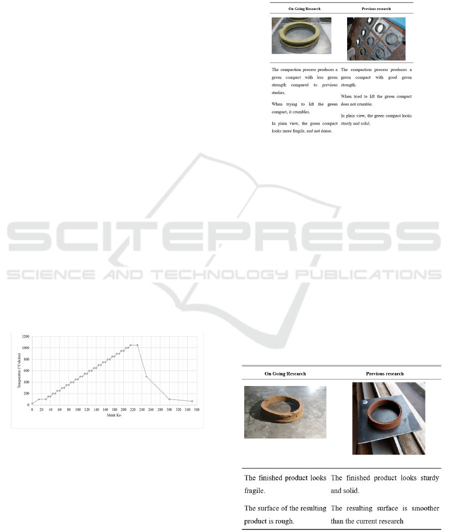
4.2.2 Compacting
The compaction process is carried out and the results
are compared with previous studies that have been
carried out in Polman, with the comparison results
which can be seen in Figure 10.
Figure 10: Comparison of green compacts.
The difference that occurs is caused by the
compaction carried out. In previous studies,
compaction was carried out in stages with the aim that
the print cavity could be completely filled. In the
current study, the same method cannot be used, due
to different geometric shapes. So that to optimize the
formation of a green compact, compaction is only
done once, although with this method there are still
shortcomings that affect the results which can be seen
in the discussion of density testing.
4.2.3 Sintering
After the compaction process is carried out, although
the green compact obtained has poor quality, a
sintering process is carried out in order to see the
characteristics and properties of the finished product.
Figure 11: Comparison of finished products.
Experimental Study of Single Action System Compacting Tool in Sealface Formation with Undercut
875
4.3 Testing Process
After carrying out all stages of the process of forming
powder metallurgy technology, then testing is carried
out. There are two mechanical properties that will be
seen, namely hardness and density. Both of these
properties are quite crucial mechanical properties of
a sealface, both in terms of function and in terms of
manufacturing methods. In terms of function, the
sealface is an important component that has an
important role in sealing leaks with a friction
mechanism so that the wear level needs to be
considered. However, due to the availability of
facilities and cost, the authors take one other
mechanical property that has a relationship with wear
and tear, namely hardness (Mokhtar, 1982).
Meanwhile, in terms of manufacturing methods, the
process of making sealface products is a powder
compaction method. So it is necessary to see the
results of product density. These limits are taken for
the standard sealface used for centrifugal pumps, with
water type fluid (Tolbert et al., 1992).
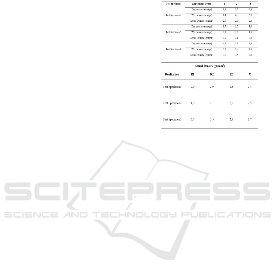
4.3.1 Density Test
The hardness test standard used refers to ASTM
B311. This method applies the Archimedes principle
to determine the density of a sample by weighing the
test specimen in air (dry measurement) and then in a
floating liquid (usually distilled water) (wet
measurement). Then this density is compared with the
theoretical density (Taylor, McClain, Berrty, 1999).
The test specimen used is a finished product sealface
with an undercut.
4.3.2 Hardness Test
The author chose to use the Vickers hardness test, in
which the testing standard used refers to ASTM E384.
The author decided to use this type of test because the
indentation area of the test specimen is quite narrow,
so a small indenter is required. Similar to density
testing, the test specimens used are finished products
that have been polished to obtain a flat and glossy
surface.
4.4 Analysis of Test Results
4.4.1 Density Test
In Figure 12, it can be seen that the density value
obtained after carrying out density testing on the test
specimen.
Figure 12: Density test data.
Based on the data that has been taken, it is known
that this value is far from the nominal limit used as a
reference. This could be because the formation
method used is not the same, from the existing
references it is not explained about the method used.
Therefore, this study compared with research
related to the formation of sealface rings with powder
metallurgy technology (Fachrul Rozy, Kurniawan),
where the results showed that the highest density
obtained was 3.00 gr/mm
3
. This value has a
difference of 0.3 gr/mm
3
from the highest density
value (2.7 gr/mm
3
) in this study. The difference in the
results is not that far, it proves that the process stages
and the same process parameters that have been
adjusted can produce characteristics that are not much
different. Indeed, the resulting density value has a less
value, this can be caused by differences that occur in
the compaction process.
Differences in density can occur due to the lack of
metal powder present in the mold cavity, as well as
the unevenness of the compaction force applied.
There are variations in thickness (on the undercut) on
the product and the use of ring settings that are the
cause.
The pressure applied to the powder product is
aimed at reducing the porosity by increasing the
contact points between the powder particles.
However, because during compaction a ring setting is
used and there is an undercut shape, the compaction
load does not directly affect the mixture and the
compaction is restrained and only compacts the top
part of the green compact. So if you look at the
results, the green compact is a little dense at the top
of the green product.
iCAST-ES 2022 - International Conference on Applied Science and Technology on Engineering Science
876
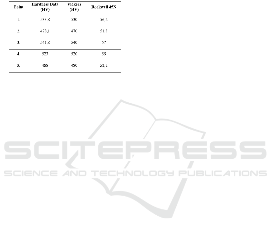
4.4.2 Hardness Test
In Figure 13, it can be seen that the hardness value
obtained after carrying out the hardness test on the
test specimen.
Figure 13: Hardness test data.
The maximum hardness is 57 Rockwell-45. If the
maximum value is compared with the table for the
material properties of the sealface, it is known that the
hardness obtained has not reached the standard
nominal value (86-88 Rockwell-45). The hardness
results obtained can be increased again, by increasing
the sintering temperature. When the results of this
study are compared with previous studies, the results
are not so far off. In this study, the sintering process
was carried out at a temperature of 1050°C and the
maximum hardness was obtained, namely 514.17 HV
510 HV 54.7 Rockwell-45 N.
4.5 Further Studies
Based on the discussion of the results of the formation
and test data, it ca be said that the sealface product
with undercut in this study was not good and was
classified into a reject product. This is based on the
following results:
• Judging from the final result of the powder
metallurgy process. The finished product has the
characteristics of being brittle and having a
rough surface. A rough surface indicates
imperfect compaction, so that the SiC grains are
still in their original shape and are not deformed.
Meanwhile, brittle characteristics can occur
because the product has poor interparticle bonds
due to incomplete compaction.
• Judging from the results of the stages of the
compaction process. At the stage of the
compaction process, a green compact was
obtained with brittle characteristics and poor
green strength. This can be seen from the green
compact's ability to maintain its shape. When
subjected to slight shocks (held manually by
hand) the green compact tends to crumble.
From these results, the authors decided that further
studies were needed. Further studies are aimed at
providing recommendations for improvements that
need to be made based on the author's observations
during the process of forming sealface products with
undercuts. The recommendations for improvement
that the authors propose are expected to improve
existing deficiencies.
The following are failure points that are the focus
of improvements that need to be made, the results of
the author's observations:
• The resulting green compact has poor green
strength, so it is easy to crush. This can be
caused by the compacting process that does not
reach the proper density.
• The molding mechanism that causes cracks in
the green compact.
• The process of releasing the mold that still uses
conventional methods
5 CONCLUSION
Based on the results of research on an experimental
study of single-action system compacting tools in
sealface formation with undercuts, the following
conclusions can be drawn:
Machines and tools with single-action system
compacting tools are not suitable for use in making
class 3 and class 4 powder metallurgy products.
The assessment of the feasibility of this single-
action compacting tool machine is based on the
following results: Observation of phenomena that
occur in each powder metallurgical process, which
discusses the compaction process a lot both in terms
of compaction work, compaction results, and the
effect of compaction results on the finished product
in terms of quality and characteristics. the final
product The compaction process is the main focus in
this discussion because the machine used plays an
important role in the stages of the compaction
process.
REFERENCES
Kurniawan, O., & Yudianto. (2014). “Kajian Kegagalan
Kinerja Sil Mekanik Produksi Dalam Negeri,”. Seminar
Nasional - XIII-Rekayasa Dan Aplikasi Teknik Mesin.
No., Hal.
Experimental Study of Single Action System Compacting Tool in Sealface Formation with Undercut
877

Syafi’i, M., & Priangkoso, T. (2018). “Penggantian Gland
Packing Ke Mechanical Seal Pada Pompa Oli TCU Di
PT. Polidayaguna Perkasa Ungaran,”. Semarang.
Wijaya, R. (2018). “Landasan Teori - Mechanical Seal,”.
Jakarta.
Fachrul Rozy, O, P., & Kurniawan, “Analisis Pembentukan
Sealface Dengan Teknologi Metalurgi Serbuk
Menggunakan Metode Taguchi Dan Teknik Grey
Relational Analysis,” J. Teknol. Dan Rekayasa
Manufaktur (JTRM) POLMAN BANDUNG.
Groover, M, P. (2010). “Powder Metallurgy,” in
Fundamental of Manufacturing Materials, Processes,
Andsystem, 4th Ed., Danvers: John Wiley & Sons, Inc,.
Flitney, R. (2007). Seals and Sealing Handbook, 5th Ed.
Oxford.
Kalpakjian, S., & Schmid, S, R. (2009). “Powder
Metallurgy Processing and Equipment,” in
Manufacturing Engineering and Technology, 6th ed.,
New York: Pearson.
Samal, P., & Newkirk, J. (2015). Materials Standards and
Test Method Standards for Powder Metallurgy. ASM
Handb, 7, 45-51.
Torosyan, K. S., & Pak, V. G. (2019, June). Influence of the
binder composition on the properties of the silicon
carbide green compacts and sintered parts prepared
from the powders produced by SHS. In IOP Conference
Series: Materials Science and Engineering (Vol. 558,
No. 1, p. 012052). IOP Publishing.
Upadhyaya, G. S. (1997). Powder metallurgy technology.
Cambridge Int Science Publishing.
Mokhtar, M. O. A. (1982). The effect of hardness on the
frictional behaviour of metals. Wear, 78(3), 297-304.
Tolbert, L. M., Nesselroth, S. M., Netzel, T. L., Raya, N.,
& Stapleton, M. (1992). Substituent effects on
carbanion photophysics: 9-arylfluorenyl anions. The
Journal of Physical Chemistry, 96(11), 4492-4496.
Lobanoff Val, S., & Ross, R. (1992). Centrifugal pumps:
Design and Application.
Kafkas, F., Karataş, Ç., Sozen, A., Arcaklioğlu, E., &
Saritaş, S. (2007). Determination of residual stresses
based on heat treatment conditions and densities on a
hybrid (FLN2-4405) powder metallurgy steel usi
ng
artificial neural network. Materials & design, 28(9), 2431-
2442.
R., P., Taylor, S., T., McClain, J., T., Berrty. (1999). “Uncertainty
Analysis of Metal-Casting Porosity Measurements Using
Archimedes’s Principle,” Int. J. Cast Met. Res. Vol., 11. No.,
4. Hal., 247–257.
Hardness, A. B. (1999). Standard Test Method for
Microindentation Hardness of Materials. ASTM Committee:
West Conshohocken, PA, USA, 384, 399.
iCAST-ES 2022 - International Conference on Applied Science and Technology on Engineering Science
878
