Manufacturing Process of Transverse Slider on Civil Building 3D
Printing Machine
Novi Saksono, Heri Setiawan and Arya Mustova
Polytechnic for Manufacturing Bandung, Indonesia
Keywords: Slider, Manufacturing Process, 3D Printing.
Abstract: The transverse slider is one of the components in the 3D machine civil building printing which serves to help
bring the nozzle to the coordinates according to the desired building design in order to produce the shape
according to the design. 3D machine printing Civil buildings require a device designed to be a carrier for other
components. Transverse slider will carry the nozzle with the help of the motor movement, then with the help
of the control the slider will move according to its coordinates so as to help bring the nozzle to the coordinates
of the building design. The construction of the transverse slider on the Civil Building 3d printing machine is
carried out by machining and fabricating the parts such as lathe, milling, grinding, and welding. After the
Slider is completed and realized at the Bandung Manufacturing Polytechnic Department of Manufacturing
Engineering, it is hoped that the Slider can be used for the manufacture of civil buildings and function properly
and be useful for the Polman academy, and the State of Indonesia.
1 INTRODUCTION
Along with the times, the manufacturing industry is
always developing continuously so that advances in
manufacturing technology can simplify and speed up
the production process, as well as its relation to civil
technology that applies the Additive Manufacturing
method by means of 3D Print for building
construction. Additive Manufacturing is a
manufacturing process by adding material in layers so
that it can form something called finished product,
this building construction can be operated by 3D Print
which processing time is relatively faster compared to
manufacture by human labor.
3D Print building or 3D building concrete casting
machine (3D Concrete Building Printing) has a
working principle similar to 3D Print in general,
namely the FDM type, where the building to be
printed can be formed by adding concrete material
and removing it layer by layer through a nozzle whose
movement is operated by the program. 3D Print this
building requires nozzle for Secrete ingredient
geopolymer which becomes ingredient building, so it
is necessary sliders for bring nozzle to the desired
coordinates so that the designed building could
formed.
The working principle of the 3d printing
transverse slider for civil buildings is that the servo
motor will rotate according to the direction of the
computer. The servo motor will turn the gears on the
rack gear to move Slider according to coordinates.
The slider will bring the nozzle to form the desired
civil building design.
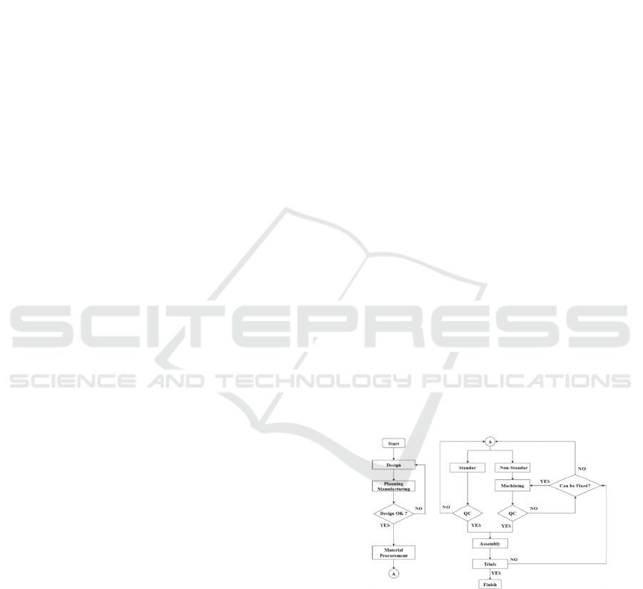
Figure 1: Flowchart manufacturing transverse sliders.
2 SOLUTION METHODS
In this solution method, it begins by making design
based on found references. After To do planning start
the planning process making about how sliders this
will made. After planning done so start at stage
material procurement, material procurement is
806
Saksono, N., Setiawan, H. and Mustova, A.
Manufacturing Process of Transverse Slider on Civil Building 3D Printing Machine.
DOI: 10.5220/0011890000003575
In Proceedings of the 5th International Conference on Applied Science and Technology on Engineering Science (iCAST-ES 2022), pages 806-812
ISBN: 978-989-758-619-4; ISSN: 2975-8246
Copyright © 2023 by SCITEPRESS – Science and Technology Publications, Lda. Under CC license (CC BY-NC-ND 4.0)
divided into 2, namely standard materials and non-
standard materials. On standard materials done QC
for knowing can the material used for construction
sliders machine 3d printing Building Civil. On non-
standard materials apply machining process for make
the desired part, after that then the part already
through the machining process enter Step QC for be
measured can parts used in construction sliders.
After all parts collected so start assembly process
is carried out or assembly for shape construction
sliders transverse. After the construction is done
assembled, a trial is carried out on the slider
construction to find out whether the slider can
function properly or not.
Slider already experience trial stage and test
results obtained that sliders could used for
construction machine 3d printing building Civil , then
the manufacturing process sliders transverse done.
2.1 Design
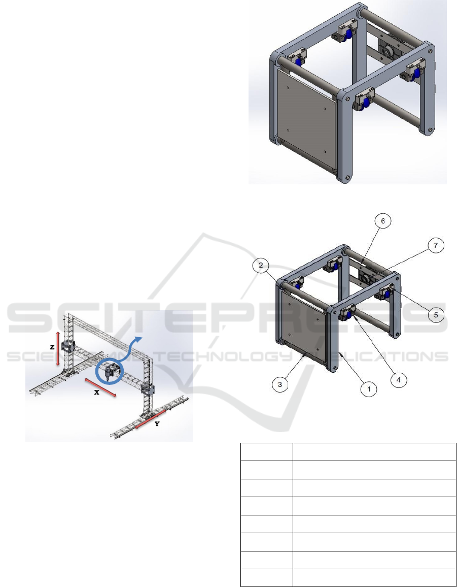
Slider transverse is the slider that brings the nozzle to
the required coordinates, the placement of the
transverse slider on the construction of a 3d printing
machine for civil buildings as in the following
picture:
Figure 2: Construction machine 3d printing.
slider is on the x-axis carrying the nozzle to direct the
nozzle to print the geopolymer according to the
desired design.
The design for the transverse slider is made as
follows:
Figure 3: Design slider.
Figure 4: Parts slider.
Table 1: Part names Slider.
No Part Component Name
1 Slider Frame
2 Bracket Mount Pipe
3 Bracket Plate Nozzle
4 Wheel Assy
5 Wheel Spacers
6 Servo Motor Bracket
7 Gearbox Nema
Manufacturing Process of Transverse Slider on Civil Building 3D Printing Machine
807

design frame Sliders:
Figure 5: Parts frame sliders.
Table 2: Part names frane sliders.
No Part Name
1 U- frames
2 Connecting Pipe
3 Shaft cover
design assy Wheels:
Figure 6: Parts wheel assy.
Table 3: Part names wheel.
No Part Component Name
1 U Groove Wheel
2 Wheel axle
3 Spacers
4 Bearing SKF 6004
5 Shaft Support
2.2 Material
2.2.1 Standart Material
Table 4: Standard components.
No
Part
Name
Specification
Picture
1
Bearing SKF 6004
2
Shaft
Support
SHTCMN
20
3 Bolt
7000454
7040172
7040140
7000182
DIN933
2.2.2 Non-Standard Material
Table 5: Components non-standard.
No
Part
Name
Specification Picture
1
Frames
Slider
Junk
aluminum
2
Retainin g
Pipe
S45C
3
Shaft
Cover
ST37
iCAST-ES 2022 - International Conference on Applied Science and Technology on Engineering Science
808

Table 5: Components non-standard. (cont.)
4
Mount
bracket
pipe
S45C
5
Bracket
Plate
nozzle
ST37
6
Servo
Motor
bracket
ST37
7
Wheel
PTFE
8
Shaft
ST37
9
Spacers
ST37
10
Top
wheel
spacer
ST37
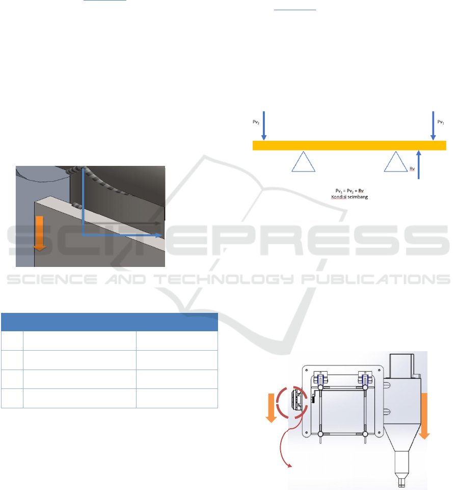
2.3 Calculation
Figure 7: Load from nozzle.F.
Figure 8: Forces acting on bolts.
Known:
Table 6: Nozzle Technical Information.
No Technical Information Score
1 Nozzle Mass 107.82 Kg
2 Yield strength ST 37 250 MPa
3 Sectional area M10 bolt 52.30mm2
σ
pm
= R e / S f
τ
pm
= 0.7 x σpm
(1)
= 250 / 2
= 125 N/mm
2
= 0.7 x 125 N/mm
2
= 87.5 N/mm
2
Description
σ
pm
=
Voltage pull
/normal clearance (N/mm
2
)
Re = Resistant
extension (N/mm
2
)
τ
pm
= Permissible shear
stress (N/mm
2
)
Sf = Safety factor
Manufacturing Process of Transverse Slider on Civil Building 3D Printing Machine
809
⁂Safety Factor for static loading = 1.2 – 2
• Maximum load of M10 baut bolt
τ = F / A (2)
F= τ x A
= 87.5 x 52.30
= 4576.25
N
(3)
The force from the nozzle is 1078 N, it can be said
that 1 M10 bolts are able to withstand the nozzle load
However, with all considerations, 4 M10 bolts are
used.
Description
τ = sheer stress (N/mm2)
A = Cross-sectional area (mm2)
• Determining the shear stress received by the
bolt.
F = 1078 N
Loading divided by 4 bolts
F = 1078 N/4 = 269.5 N
= F / A
= 269.5 N / 52.30 mm
2
= 5.15 N/mm
2
(4)
W
elde
d
p
ar
t
Figure 9: Force on welding.
Table 7: Welding technical information.
No Technical Information Score
1 Permit voltage σ 125 N/mm
2
2
Coefficient γ
2
0.5
3
Welded length (l
1
)
160.45 mm
4 Hem welding
3 mm
• Welding clearance voltage.
σpm = Re/Sf
= 250 / 2
=125 N/mm
2
σ
w
pm = γ
2
x σpm
= 0.5 x 125
= 62.5 N/mm
2
(5)
Description
σ
pm
= Tensile
stress/normal allowable
(N/mm
2
)
Re = Resistant
extension (N/mm
2
)
σ
w
pm = Allowable
weldin
g
stress (N/mm
2
)
sf = Safety factor
⁂Coefficient γ2 for weld seams that have not been
tested = 0.5
• Welding area
L = l
1
– 2A
=160.45 – 2 (3)
= 160.45 – 6
= 154.45 mm
Aw = L x A
= 154.45 x 3
= 463.35 mm
2
m
(6)
• The stress that occurs in the weld seam
σ = F / Aw
= 539 N/463.35 mm
2
= 1.16 N/mm
2
≤ σ
w
izin
≤ 62.5 N/mm
2
≤ 62.5 N/mm
2
(7)
⁂The force given by the nozzle is 1078 N, welding
is carried out on 2 pipes as a support, then the load is
divided on both pipes into F = 1078 / 2 = 539 N
Figure 10: Balance.
Note;
Pv
1
= Load from nozzle
Pv
2
= Load of motor
Rv = Resistance vertical from the strength of
resistance M6 bolt shear stress in the rack along
the pillar
Pv
1
= Pv
2
+ Rv (8)
1078N = 23N + Rv
Rv = 1055N
Figure 11: Balance on the slider.
mo
1Rac
k
is hel
d
using 6 M6 Bolts,
on the X-axis
ill 6
m
iCAST-ES 2022 - International Conference on Applied Science and Technology on Engineering Science
810
τ = F / A F = τ x A
(9)
= 87.5N/mm
2
x 17.89mm
2
= 1565.37 N
≥ 1055
N
≥ 1055 N
≥ 1055 N
≥ 1055
N
(10)
The force from the nozzle is 1078 N, it can be said
that 1 M6 bolt is able to withstand the nozzle
load.While the pillars are installed 24 M6 bolts.
2.4 Machining Process
Information :
F = Foundry CML = CNC Milling
HG = Hand Grinder BW = Bench Work
BS = Bend Saw ML = Milling
BO = Bor GC = Grinding Cut
L = Lathe QC = Quality control
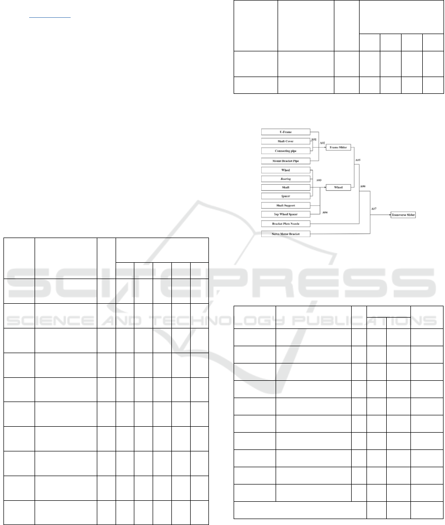
Table 8: Stages of the construction process Slider.
No.
Part Name
Qty
( p c s )
Stages of the Working
Process
1 2 3 4 5
SM-01-
01
U-frames
2
F
CML QC
SM-01-
02
Connecting Pipe
4 GP HG QC
SM-01-
03
Shaft Cover
8 BS L QC
SM-02
Bracket Mount
Pipe
2 GC HG QC
SM-03
Bracket Plate
N
ozzle
1 HG BO QC
SM-04-
01
U Groove Wheel
4 BS BW L QC
SM-04-
02
Shaft
4 L QC
SM-04-
03
Spacers
4 GC BW L BO QC
SM-05
Spacers top
wheel
8 ML BO QC
SM-06
Servo Motor
Bracket
2 HG BO QC
Information :
EW = Electric Welding Th = Adjustment/Thread HG
= Hand Grinder QC = Quality control
Table 9: Stages of the process of working on sub- assembly
parts.
No.
Part Name
Qty
( pcs )
Stages of the
Working Process
1 2 3 4
SM-01-00 Slider Frame 1 EW HG Th QC
SM-04-00 Assy Wheel 1 Th QC
2.5 Assembly
Figure 12: Assembly Diagram.
2.6 Estimated Time
Table 10: Estimated Time.
No.Part Part Name Qty
Estimate
Total
(Minute)
TNC TC
SM-01-01 Frame 2 85 90 175
SM-01-02 Connecting pipe 4 17 0,94 17,94
SM-01-03 Shaft cover 8 57 49,6 106,6
SM-02-00 Bracket Mount Pipe 2 11 7,72 18,72
SM-03-00 Bracket Plate Nozzle 1 20 80,3 100,3
SM-04-01 Wheel 4 25 100 125
SM-04-02 Shaft 4 35 55,4 90,4
SM-04-03 Spacer 4 16 9,4 26,4
SM-05-00 Top Wheel Spacer 8 41 95 136
SM-06-00 Servo Motor Bracket 2 19 95,3 114,3
Total : 326 583,66 910,66
Adding with 33.95 welding time, the estimated
machining process = 944.61 Minutes
Manufacturing Process of Transverse Slider on Civil Building 3D Printing Machine
811

2.7 Estimate Cost
Table 11: Estimation Cost.
No. Detail cost Total cost
1 Machining Process Rp 458.100
2 Operator (man power) Rp 227.415
3 Standart Part Rp 4.114.876
4 Non standart part Rp 2.244.590
5 Overhead cost Rp 1.426.996
Total Cost : Rp 8.561.977
3 CLOSING
1. The construction have dimensions 540 x
568.30 x 720.50 mm with weight 56 Kg, using
4 wheels, 2 pieces frame, 4 connecting pipes,
motor bracket on the side right and nozzle
bracket on the side left . Materials used in the
form of aluminum, carbon steel and PTFE.
2. In machining process moment making
Transverse slider through various machining
and fabrication processes like milling, lathe,
grinding, and welding.
3. Estimate time needed to make Transverse
slider on machine 3d printing of buildings
civil is 15.74 Hours
4. Estimate cost required for make Transverse
slider on machine 3d printing of buildings
civil is Rp8.561,977
REFERENCES
Goeritno Wahjoe; Wikanda Uli; and S.Ecep. 2000. Standar
polman Seri 0 Bandung; Bandung Polytechnic of
Manufacturing.
Elemen Mesin 3 Perhitungan Elemen Mesin; Bandung
Polytechnic of Manufacturing.
Pendidikan Dosen, 2. 2022. Transmission is. July 19, 2022
accessed from Transmission are – Functions, Types,
Components & Working Methods (dosen
Pendidikan.co.id)
Waloeyo, Gamawan A. 2021. Biaya Dasar PPC. Bandung;
Bandung Polytechnic of Manufacturing.
Susanti O. 2021. DESIGN AND CONSTRUCTION
OF TAILSTOCK ON MINI 2 AXIS CNC
LATHE MACHINE AT MANUFACTURING
POLYTECHNIC, BANDUNG. (BANDUNG
MANUFACTURING POLYTECHNIC)
Gallavotti, Giovanni. The elements of mechanics. Springer
Science & Business Media, 2013. Mechanics and
Elements PDF Engine (Free 220 Pages)
(pdfdrive.com); July 15, 2022; accessed from
pdfdrive.com
Hashim, Jasmi. The production of metal matrix composites
using the stir casting technique. Diss. Dublin City
University, 1999. Casting Technique Metal &
Treatment Hot PDF (196 Pages) (pdfdrive.com); July
16, 2022; accessed from pdfdrive.com.
iCAST-ES 2022 - International Conference on Applied Science and Technology on Engineering Science
812
