
Progressive Hybrid Stamping Tool Development on Automotive
Components Stay Headlight Material SPC270C
Aida Mahmudah
a
, Metha Islameka
b
, Rofan Yulian Romansyah
c
and Sigit Permana
Design Engineering Department, Politeknik Manufaktur Bandung, Jl. Kanayakan No. 21, Bandung, Indonesia
Keywords: Progressive Hybrid Tool, Stay Headlight, SPC270C.
Abstract: Stay headlight component is a product that requires several stages in its manufacture. The production process
used one compound tool and one group tool mounted on two different press machines. Progressive hybrid
tools can be used to reduce the number of operators, press machines, and speed up processing times. A
progressive hybrid tool is a stamping tool used to produce components from sheet metal materials. In
progressive hybrid tools, the combined process consisting of cutting and forming processes occurs
continuously. In this study, the initial development of a progressive hybrid tool was carried out to produce a
stay headlight component that functions as a vehicle headlight holder. The material used is SPC270C, with a
thickness of 1.6 mm. The design method used is VDI 2222 (Verein Deutsche Ingenieure 2222), which consists
of 4 main stages: planning, conceptualising, designing, and finishing. This early-stage development results in
a progressive hybrid tool design consisting of 11 process stations with a material efficiency of 57.6%. The
tool's dimensions are 845 mm long, 640 mm wide, and 370 mm high. The total force required on this tool is
64.86 tons.
1 INTRODUCTION
The automotive industry is one of the main sectors
contributing to the national economy. The automotive
industry is currently experiencing an increase. This is
in line with the development of technology and
components in vehicles. The development of
manufacturing processes to improve the efficiency of
the production process has become a necessity for the
industry as an active player in manufacturing
activities. The stamping process is one manufacturing
process to produce components from sheet metal
materials, for example, automotive components,
medical equipment, household equipment, and so on
(Thomas et al., 2000; Su et al., 2022). Automotive
components are the most needed stamping products
with a wide variety of materials, shapes, and
dimensions. So that the development of process
quality and production acceleration is necessary in
line with the increasing demand for components
(Silva et al., 2021). The development of precision tool
technology is an alternative solution that can be done
to increase production efficiency without reducing
a
https://orcid.org/0000-0002-7124-0824
b
https://orcid.org/0000-0003-4578-8850
c
https://orcid.org/0000-0001-9216-785X
the quality of the resulting product (Shakkarwal et al.,
2021).
The stay headlight component is one of the
components on the front of the vehicle that functions
as a vehicle headlight holder. This component is made
of SPC270C material with a thickness of 1.6 mm.
This product goes through several process stages:
cutting, forming and bending. The process is carried
out using two stamping tools, the compound tool
(cutting process) and the group tool (forming and
bending process). Both tools are installed on two
different press machines with two operators.
Furthermore, based on the analysis of the stay
headlight product, the result is that the product can be
formed with a continuous process stage using one
tool, namely the progressive hybrid tool. Progressive
hybrid tools are often recommended for mass
production of stamped parts requiring complex press
operations (Karimov, 2021). By using one tool, the
number of press machines and operators needed is
reduced. This, of course, can also reduce energy
consumption and production process costs (Gen and
Yunong, 2020). Therefore, an initial step is necessary
Mahmudah, A., Islameka, M., Romansyah, R. and Permana, S.
Progressive Hybr id Stamping Tool Development on Automotive Components Stay Headlight Material SPC270C.
DOI: 10.5220/0011806400003575
In Proceedings of the 5th International Conference on Applied Science and Technology on Engineering Science (iCAST-ES 2022), pages 375-380
ISBN: 978-989-758-619-4; ISSN: 2975-8246
Copyright © 2023 by SCITEPRESS – Science and Technology Publications, Lda. Under CC license (CC BY-NC-ND 4.0)
375

for developing the tool that will be used to produce
the stay headlight component, namely the design of a
progressive hybrid tool consisting of a combination
of cutting and forming processes which are carried
out gradually and continuously. The design method
used is VDI 2222 (Verein Deutsche Ingenieure 2222),
which consists of four main stages: planning,
conceptualising, designing and finishing. The design
of a progressive hybrid tool equipped with technical
documents for each component to be fabricated as
well as machine specifications following the tool
geometry and machine tonnage required were carried
out in this study.
2 MATERIAL AND METHOD
2.1 Stay Headlight
The stay headlight product functions as a headlight
holder for two-wheeled motorised vehicles. This
product is made of SPC270C material with a
thickness of 1.6 mm and has Rm 270 N/mm
2
. Figure
1 shows the shape of the stay headlight product.
Figure 1: Stay headlight.
Product shape analysis is carried out to obtain a
fully defined product shape and size. Furthermore,
with the help of modelling software, the shape and
size of the stay headlight product are obtained. Figure
2 shows the flattened shape and the size of the stay
headlight product before it is formed.
Figure 2: Flattened shape.
2.2 Design Method
The method used in the design process of the
progressive hybrid tool for the stay headlight BEJ/AT
is VDI 2222 (Verein Deutsche Ingenieure).
According to VDI 2222, the design flowchart is
divided into four major parts: planning,
conceptualising, designing and completing. Figure 3
shows the VDI 2222 flowchart used.
Figure 3: Design method VDI 2222.
2.2.1 Design Parameters
The design parameters are used as a reference to
achieve the given requirements. Table 1 shows the
design parameters for the developed progressive
hybrid tool.
Table 1: Design parameters.
Demand
Qualification
Product
Dimension
According to the working
drawing
Product thickness
1.6 mm
Material
SPC270C
Tensile stress
270 N/mm
2
Press Tool
Tool assembly process
Easy to install and maintain
Tool clamping
T-slot bolt
Use of standard components
Misumi
Die height
340-450 mm
Tool safety
Miss feed sensor
Machine
Machine type
AIDA A-04
Press machine capacity
200 tons
Slide adjustment
110 mm
Upper bolster dimension
1850 × 650 mm
Lower bolster dimension
2420 × 680 mm
iCAST-ES 2022 - International Conference on Applied Science and Technology on Engineering Science
376
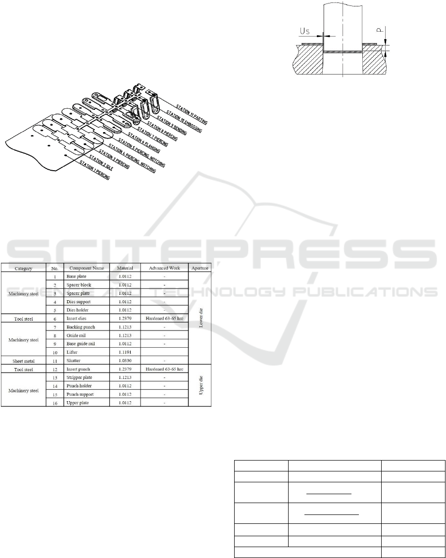
2.2.2 Design Concepting
The design concept consists of several stages: making
the layout and selecting materials for the main
components. Figure 4 shows the planned progressive
process layout. The process layout consists of 11
process stations, namely 4 piercing process stations,
2 piercing notching processing stations, 1 flanging
process station, 1 bending process station, 1
embossing process station, 1 parting process station
and 1 idle station.
Figure 4: Process layout.
Materials for the main components of this
progressive hybrid tool are shown in Table 2.
Table 2: Material of tool’s component.
2.3 Tool Design
At this stage, a tool design construction calculation is
carried out, which will determine the tool's
performance and the quality of the resulting product.
This construction calculation consists of calculating
the clearance between the punch and the die cutting,
the penetration length of the punch to the die, the
stamping force, the stripper force, and the process’s
center of gravity to result in the pre-design of a
progressive hybrid tool.
2.3.1 Cutting Clearance
Calculation of cutting clearance refers to the analysis
and table of standard MISUMI clearance selection.
Figure 5 shows the cutting clearance.
Figure 5: Cutting clearance.
Us = T × c%
(1)
Where Us is the clearance, T is the material thickness,
and c is the working factor. The working factor is
selected to be 6% for the category of extra soft
clearance on steel material. So, the cutting clearance
is 0.1 mm/side.
2.3.2 Die Penetration
Dies penetration is the penetration of the punch from
the thickness of the material strip and pushes the scrap
out of the die. Equation (2) shows the calculation of
the penetration of the die.
L
die penetration
= 1 to 3 × T
(2)
Where L
die penetration
is the length of the die
penetration. So, the die penetration is 1.6 mm to 4.8
mm. The die penetration length for this progressive
hybrid tool design is 3 mm.
2.3.3 Stamping Force
The stamping force is calculated based on the type of
process that occurs in the tool. The calculation of the
stamping force on this progressive hybrid tool is
shown in Table 3.
Table 3: Stamping Force calculation (Budiarto, 2009;
Luchsinger, H R.,198)).
Process
Equations
Force [N]
Cutting
= 0.8 . l . s . Rm
399,164.58
Flanging
=
B×s×Rm
3
× n
20,691.18
Bending
=
b × T × Rm
3
× n
2.631.10
Embossing
F
Embossing
=Ae x Kr x n
44,278.92
Stripper Force
= 10% . F Proses
46,700.66
Total Tool Force
538,082.62
Progressive Hybrid Stamping Tool Development on Automotive Components Stay Headlight Material SPC270C
377

Table 3: Stamping Force calculation (Budiarto, 2009;
Luchsinger, H R.,198))(cont.).
Process
Equations
Force [N]
Minimal
Machine
capacity
= 120% . F tool
648.624,19
2.3.4 Center Gravity of Tool
The position of the center of gravity of the tool is
important in determining the placement of the tool on
the press machine. The calculated center of gravity is
the position of the center of gravity of the process and
is usually indicated by the installation of the shank
component. The position of the center of gravity of
this progressive hybrid tool is shown in Figure 6. This
data is poured into a pre-design, as shown in Figure
7.
x =
Lx
L
(3)
y =
Ly
L
(4)
Figure 6: Center gravity of tool.
3 RESULT AND DISCUSSION
The pre-design obtained results in a tool with
dimensions of 845 mm in length, 640 mm in width,
and 370 mm in height. The minimum machine
capacity required is 64.86 Tons. The specifications of
this tool meet the machine specifications specified in
Table 1.
Validation of tool construction is carried out
through construction inspection calculations,
including spring components and punch components.
The performance of spring components must be
carried out to ensure the spring can work properly.
Figure 8 below shows the spring step diagram.
Figure 7: Pre-design.
Figure 8: Spring step diagram.
The spring used must fulfil its function as a stripper
or lifter where the selected spring force must be
greater than the required force. The results of the
inspection calculations are shown in Table 4, where
all the springs used can meet the required spring
force.
Table 4: Spring performs validation.
F
Stripper
or F
Lifter
[N]
F
Spring
[N]
Conclusion
F
Stripper 1
= 26,895.63
31,363.9
Well performed
F
Stripper 2
= 19,805.03
31,363.9
Well performed
F
Stripper 1
= 90.04
91,2
Well performed
The reaction force of the punch shall not exceed
the allowable stress of the upper plate component
material in direct contact with the top surface of the
punch. Suppose the reaction force exceeds the
allowable pressure of the material. In that case, it is
necessary to add an insert plate of a material with a
higher hardness level so that the upper plate
components are not damaged.
p =
Fs
A
≤p allow
(5)
Where p is the surface pressure, A is the punch head
cross-sectional area, Fs is the processing force, and p
allow is the allowable surface pressure. The allowable
surface pressure for unhardened steel with impact
loading mode is 40 N/mm
2
(Budiarto, 2012). From
the calculation of the surface pressure at each punch
iCAST-ES 2022 - International Conference on Applied Science and Technology on Engineering Science
378

that cuts the strip of material, it is found that most
piercing process stations need an insert plate.
In addition, to examine the punch construction
based on surface pressure, the punch buckling
phenomenon was also checked. Buckling is
instability that leads to failure, caused by a structure’s
inability to maintain its original shape so that it
changes form to find a new balance. In this case, the
processing force that occurs in the punch (F
process
)
must be less than the force that will cause buckling in
the punch (F
buckling
). The magnitude of this buckling
force is strongly influenced by the free length of the
punch in the punch mounting construction model, as
shown in Figure 9.
𝐹
𝑏𝑢𝑐𝑘𝑙𝑖𝑛𝑔
=(
π
2
×E×I
l
2
) ÷ Sf ≥ 𝐹
𝑝𝑟𝑜𝑐𝑒𝑠𝑠
(6)
Figure 9: Free length of punch.
Considering the punch construction that has the
most potential for buckling, piercing the slot shape at
station 7, it is found that the force that will cause
buckling, F
buckling
= 2,321,081.56 N, while the process
force that occurs at the station is 11,567.24 N. Thus,
it can be seen that the punch will not undergo
buckling during the cutting or forming of the product.
Construction validation carried out on spring and
punch components can meet the construction
requirements of the designed progressive hybrid tool,
which is then tested after the tool fabrication is
completed. The overall tool design can be seen in
Figure 10.
The results of this progressive hybrid tool design
contribute to the use of the press machine and the
number of operators. In addition, increasing the
amount of production in one manufacturing process
because with the layout process applied to this tool,
two products are obtained in 1 stamping process. The
following Table 5 shows a comparison of the
production process of stay headlight components
using the previous tool and the progressive hybrid
tool.
(a)
(b)
Figure 10: Progressive hybrid tool (a) top opening and (b)
lower opening.
Table 5: The comparison of stay headlight production
process.
Comparison
Compound tool
& group tool
Progressive
hybrid tool
Number of
machines
2
1
Number of
operators
2
1
Number of
products
in one stroke
1
2
4 CONCLUSION
The development of a stamping tool for the
production process of stay headlight components has
resulted in a progressive hybrid tool with 11 process
Progressive Hybrid Stamping Tool Development on Automotive Components Stay Headlight Material SPC270C
379

stations. Tool dimensions are 845 mm long, 640 mm
wide, and 370 mm high. The force required on this
tool is 64.86 Tons and can be used on the press
machine AIDA A-04 engine with a capacity of 200
tons. By using a progressive hybrid tool, the number
of machines and operators can be reduced, and even
the production speed can be increased by increasing
the number of products produced in one stamping
process.
REFERENCES
Budiarto (2009). Presstool 1. Bandung. Politeknik
Manufaktur Bandung.
Budiarto. (2009). Presstool 2. Bandung. Politeknik
Manufaktur Bandung.
Gen, Y., & Yunong, W. (2020, August). Progressive
stamping process and die design of high strength steel
automobile structural parts. In Journal of Physics:
Conference Series (Vol. 1605, No. 1, p. 012063). IOP
Publishing.
Hakim, Adies Rahman. (2005). Kekuatan Bahan Dasar.
Bandung. Politeknik Manufaktur Bandung.
Karimov, R. (2021). PLANNING OF BELT BRIDGE FOR
UNSYMMETRICAL PROGRESSIVE STAMPING.
Scientific progress, 2(2), 616-623.
Luchsinger, H R. (1984). Tool Design 2. Zurich. Swiss
Technical Cooperation and Swisscontact.
Shakkarwal, P., Kumar, R., Sindhwani, R. (2021).
Progressive Die Design and Development Using
AutoCAD. In: Joshi, P., Gupta, S.S., Shukla, A.K.,
Gautam, S.S. (eds) Advances in Engineering Design.
Lecture Notes in Mechanical Engineering. Springer,
Singapore. https://doi.org/10.1007/978-981-33-4684-
0_54
Silva, J. C., da Silva, F. J. G., Campilho, R. D. S. G., de Sá,
J. C. V., & Ferreira, L. C. R. N. P. (2021). A model for
productivity improvement on machining of components
for stamping dies. International Journal of Industrial
Engineering and Management, 12(2), 85.
Su, T., He, T., Yang, R., & Li, M. (2022). Topology
optimization and lightweight design of stamping dies
for forming automobile panels. The International
Journal of Advanced Manufacturing Technology,
121(7), 4691-4702.
Thomas, W., Oenoki, T., Altan, T., (2000). Process
simulation in stamping – recent applications for product
and process design. Journal of Materials Processing
Technology. Volume 98. Issue 2. Pages 232-243. ISSN
0924-0136.
iCAST-ES 2022 - International Conference on Applied Science and Technology on Engineering Science
380
