
Assessment of the Operability of a Low-depth Concrete Anchor of
Overhead Line of Type AM using Modeling
Alexander Viktorovich Paranin
a
Ural State University of Railway Transport, Yekaterinburg, Russia
Keywords: Overhead line, anchor, deepening, soil, concrete, calculation, modeling, mechanical stress, pressure, finite
element method, elastic and plastic deformations.
Abstract: The article analyzes the design of a concrete low-depth anchor of overhead line of type AM. This design was
recently developed by Tolmachevsky Plant of Reinforced Concrete and Metal Structures. It is fundamentally
different from the design of widely used three-beam reinforced concrete anchors of the overhead line. To
assess the operability of the structure, a finite element model of the anchor itself placed in the ground was
created. This model is two-dimensional, taking into account plastic deformations of soil and concrete, as well
as mechanical contact of these materials. As a soil, sand is considered as weakly bearing: the worst conditions
during operation. According to the calculation results, the fields of equivalent mechanical stresses and
pressures arising in the soil and concrete are determined. The analysis of the results confirms the operability
of the AM anchor in the considered ground conditions with a force in the anchor cable of the overhead line
up to 90 kN inclusive.
1 INTRODUCTION
LLC Tolmachevsky Plant of Reinforced Concrete
and Metal Structures has recently developed a design
of a concrete low-depth anchor of the overhead line
of type AM. It is fundamentally different from the
design of widely used three-beam reinforced concrete
anchors of the overhead line. For example,
reinforcement is completely absent, its weight and
dimensions are significantly larger than the standard
existing anchors of the overhead line. The
manufacturer has applied for a patent for this design.
For this reason, the manufacturer does not provide the
results of calculation and physical tests of such a
design for the operating organization Directorate for
Energy Supply of JSC "Russian Railways". In this
regard, the anchor's operability was checked in a
calculated manner.
The calculation of such a structure by analytical
methods set out in regulatory documents (Standards
for the design of the overhead line STN CE 141-99,
2001; BSI Standards Publication, 2020) concerning
calculations and standards for the design of an
overhead line seems extremely complex and not fully
adequate, since all formulas are focused on the main
a
https://orcid.org/0000-0002-9522-3359
types of existing foundations with deep laying. In
addition, the top layer of soil up to 0.3 – 0.5 m is
usually considered non-bearing, i.e. conditionally not
resisting. Thus, the AM anchor is located almost
completely in a non-bearing layer.
Therefore, the calculation was performed using
simulation in the COMSOL Multiphysics software
package license number 9601577 in a two-
dimensional formulation.
2 MAIN PART
2.1 Materials and Methods
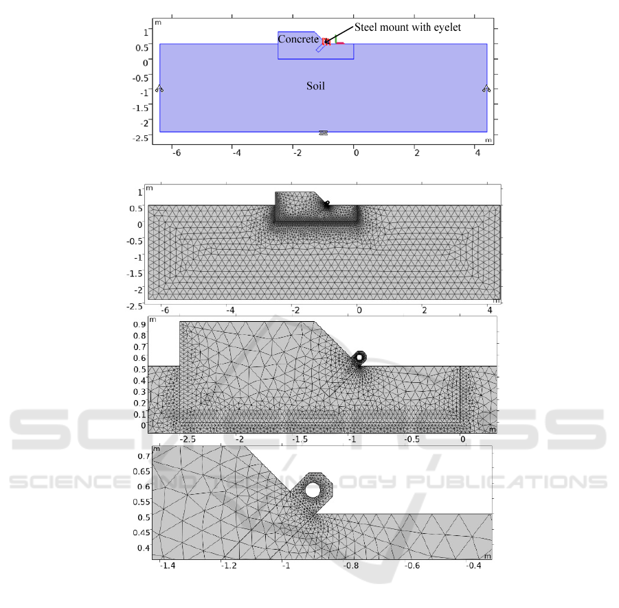
The calculation was performed on a two-dimensional
model. A concrete anchor with a steel eye for the
anchor guy is buried in the ground at 0.5 m. The
geometry of the computational domain with signed
materials is shown in Fig. 1. Sand was chosen as the
soil as a weak-bearing one, concrete was taken from
the B30 grade, carbon steel was used for mounting
with an eye.
300
Paranin, A.
Assessment of the Operability of a Low-depth Concrete Anchor of Overhead Line of Type AM using Modeling.
DOI: 10.5220/0011584100003527
In Proceedings of the 1st International Scientific and Practical Conference on Transport: Logistics, Construction, Maintenance, Management (TLC2M 2022), pages 300-304
ISBN: 978-989-758-606-4
Copyright
c
2023 by SCITEPRESS – Science and Technology Publications, Lda. Under CC license (CC BY-NC-ND 4.0)
The COMSOL Multiphysics software package
uses the principle of virtual operation to describe
continuum mechanics. This principle states that the
internal work performed by infinitesimal
deformations under the influence of internal stresses
is equal to the external work performed by the
corresponding virtual displacements under the
influence of external loads. For this purpose, Green-
Lagrange deformations and second Piola-Kirchhoff
stresses S (Pascon, 2013) are used. Such a
formulation is commonly called a complete
Lagrangian. The displacement field u is used as the
calculated variable (u is the horizontal component, v
is the vertical component). In the described two-
dimensional model, the hypothesis of plane
displacements is accepted.
A linear elastic model was chosen for steel, i.e.
there are no plastic deformations. Plastic deformation
models are set for concrete and soil. The model of
plastic deformation for soil was adopted by Drucker
— Prager (Wojciechowski, 2018; Liu, 2017) with the
calculation of its coefficients based on the adhesion c
and the angle φ of the internal friction of the soil
(Jiang, 2012). Plastic deformation is specified for
concrete according to the Ottosen model (Ottosen,
1996; Zhang, 2020).
Normal zero normal displacements are set on the
lateral boundaries of the soil: n · u = 0. The condition
of immobility u = 0 is set at the lower boundary of the
soil.
Figure 1: Geometry of the calculated area with signed materials.
Figure 2: The finite element grid used in the calculation.
Assessment of the Operability of a Low-depth Concrete Anchor of Overhead Line of Type AM using Modeling
301

Figure 3: Plot of equivalent Mises stresses with a guyline force of 0, 40 and 90 kN (red arrow).
Figure 4: Plot of the pressure inside the material at a guyline force of 0, 40 and 90 kN (red arrow).
Figure 5: Plot of the pressure arrows on the contact surface (the color is the value of MPa, the size of the arrow is
proportional to the pressure value in a logarithmic scale with a base of 10) with a guyline force of 0, 40 and 90 kN (red
arrow).
TLC2M 2022 - INTERNATIONAL SCIENTIFIC AND PRACTICAL CONFERENCE TLC2M TRANSPORT: LOGISTICS,
CONSTRUCTION, MAINTENANCE, MANAGEMENT
302

A mechanical contact is used at the boundary of
the soil and concrete junction. In this case, the contact
pressure is calculated by the penalty method based on
the field of concrete and soil movements. On the
connection line of the steel fastening with the eye and
the concrete foundation, the condition of continuity
of the displacement field u. The upper boundary of
the eyelet is given by the force F
anc
. When
calculating, it incrementally increases from 0 to 90
kN.
The distributed volumetric force from its own
weight is set throughout the volume.
The finite element grid is shown in Fig. 2.
The type of finite element is quadratic
serendipitous. Since mechanical contact is assumed,
geometric nonlinearity is taken into account in the
model. In other words, the equilibrium conditions are
written taking into account the deformation.
The solution is in two stages by gradually
increasing the nonlinearity.
Stage 1: the strength of the anchor guy F
ank
= 0,
under the action of its own weight, there is a gradual
stabilization of the contact between the soil and
concrete. To do this, the lower limit of the contact
pressure gradually decreases from large values to zero
and the soil adhesion gradually decreases from 0.1 to
0.03 MPa. Below 0.03 MPa, the solution is not stable.
At the same time, the anchor sags slightly in the
ground, the contact pressure is distributed mainly
along the sole.
Stage 2. Starting from the final result of stage 1,
the strength of the anchor guy begins to increase step
by step from 0 to 90 kN. The anchor is shifted to the
right and slightly upwards. The contact pressure is
redistributed mainly to the lower right corner of the
anchor. At F
ank
> 93 kN, the solution is not found.
There are too large plastic deformations.
2.2 Results and Discussion
The main results are presented in the plot of
equivalent stresses according to Mises (Fig. 3), the
pressure inside the material (Fig. 4) and the contact
pressure (Fig. 5) at a force in the anchor tie F
ank
of 0,
40 and 90 kN. The magnitude of the stresses is
indicated by color, the color scale is on the right. The
red arrow indicates the force in the anchor tie.
The figure shows a graph of the horizontal and
vertical movement of the eyelet from the magnitude
of the force in the anchor tie F
ank
.
According to the results of the calculation on a
finite element mathematical model, it follows that the
specified anchor withstands the traction force in the
anchor tie at least 90 kN when 0.5 m is sunk into the
ground with characteristics close to sand. The density,
the angle of internal friction and Young's modulus
correspond to sand, and the adhesion of 30 kPa is
closer to loam. For sand, the adhesion is up to 8 kPa.
However, with a value less than 30 kPa, the
calculation cannot be performed.
Figure 6: A graph of the horizontal and vertical movement
of the eyelet from the magnitude of the force in the anchor
tie F
ank
The anchor weight is approximately 6.2 tons,
which is three times more than three-beam anchors.
The work of the AM anchor is provided by contact
pressure on the ground in the lower right part from the
side of the anchor guy. It can be said that the anchor
conditionally "cuts" the soil at this angle and thereby
perceives the force in the anchor tie, due to the
resistance of the soil.
The movement of the eyelet is no more than 7 mm
with a guyline force of 90 kN. This is three orders of
magnitude less than the length of the anchor guy and,
accordingly, the shift of the anchor under load will
not lead to a significant weakening of the guyline
force.
It follows from the pressure diagram inside the
concrete that the greatest compression (positive
pressure) occurs in the lower right part of the anchor.
Most of the left (protruding from the ground) side of
the anchor experiences a slight compression pressure
due to its own weight. The stretched area of concrete
with negative pressure is located near the metal
anchorage for the anchor guy. But there the modulo
negative pressure is not great. It should be noted that
the design of the steel fastening in the model is
reproduced approximately. From the point of view of
the strength of concrete, there are no large stretching
zones in it, which explains the lack of reinforcement.
The maximum compression stress occurs at the lower
right corner, where the greatest contact pressure with
the ground. It is not more than 0.5 MPa, which is
significantly lower than the calculated permissible
compression resistance of concrete B30 equal to 17
MPa.
Assessment of the Operability of a Low-depth Concrete Anchor of Overhead Line of Type AM using Modeling
303

3 CONCLUSIONS
Thus, it can be said that according to the simulation
results, the design of the AM anchor is operable under
the specified conditions of sinking even in a weakly
bearing sand-type soil.
It is worth noting that there remains the question
of the expediency of using such anchors and the
conditions for their use. It is hardly possible to install
them on embankments and recesses, only at zero
levels and with reasonable necessity. They have
relatively large dimensions, a larger amount of
excavation work will be required during installation
and a crane of the appropriate lifting capacity.
REFERENCES
2001. Standards for the design of the overhead line STN CE
141-99. M.:Transizdat. p. 176.
2020. EN 50119-2020. Railway applications - Fixed
installations - Electric traction overhead contact lines.
London, BSI Standards Publication, p. 196.
Pascon, J. P., Coda, H. B., 2013. Large deformation
analysis of elastoplastic homogeneous materials via
high order tetrahedral finite elements. Finite Elements
in Analysis and Design. 76. pp. 21-38.
Wojciechowski, M. , 2018. A note on the differences
between Drucker-Prager and Mohr-Coulomb shear
strength criteria. Studia Geotechnica et Mechanica.
40(3), pp. 163–169.
Liu, K., Chen, S. L., 2017. Finite element implementation
of strain-hardening Drucker–Prager plasticity model
with application to tunnel excavation. Underground
Space (China). 2(3). pp. 168-174.
Jiang, J. F., Wu, Y. F., 2012. Identification of material
parameters for Drucker-Prager plasticity model for FRP
confined circular concrete columns. International
Journal of Solids and Structures. 49(3–4). 445-456.
Ottosen N. S., Ristinmaa M., 1996. Corners in plasticity-
Koiter's theory revisited. Int. J. Solids and Struct. 33.
25. pp. 3697-3721.
Zhang, X., Wu, H., Li, J., Pi, A., Huang, F., 2020. A
constitutive model of concrete based on Ottosen yield
criterion. International Journal of Solids and
Structures. 193-194, pp. 79-89.
TLC2M 2022 - INTERNATIONAL SCIENTIFIC AND PRACTICAL CONFERENCE TLC2M TRANSPORT: LOGISTICS,
CONSTRUCTION, MAINTENANCE, MANAGEMENT
304
