
Coordinated Track Circuits
F. R. Akhmadullin
Samara State Transport University, Samara, Russia
Keywords: Rail line, track circuit, circuit, control method, rail line status control.
Abstract: The article considers a track circuit with an adaptive track receiver, which include coordinated track circuits
that are part of correlative track circuits. This article describes a method for monitoring the condition of track
sections by comparing the voltages at the inputs of track receivers of two rail lines. The described method can
be used to monitor the condition of other rail lines.The main advantage and positive quality of the considered
track circuits is that they have the ability to function with a small insulation resistance, have a much longer
length and shunt sensitivity. In addition, these track circuits are susceptible to longitudinal asymmetry and to
changes in insulation resistance, therefore they have a number of their own features according to the algorithm
of their functioning and construction. The commissioning of coordinated track circuits increases the safety of
train traffic, facilitates the working conditions of service personnel, as well as the reliability of the interval
train traffic systems themselves.
1 INTRODUCTION
When analyzing the quality of the functioning of
track circuits (TC), one of the main criteria is to
ensure the safety of train traffic. The working
conditions of the track circuits are far from normal,
taking into account the number of destabilizing
factors and interference from the traction network.
The decisive factor in the evaluation is the degree
(high) of noise immunity of the track receiver (TR).
In order to remove or minimize the destabilizing
factor affecting the operation of the TC, coordinated
track circuits (TC) are proposed for use
Taking into account the main functional purpose
of the TC, it is necessary to pay attention to the quality
characteristic of the TR – noise immunity, which can
be evaluated on the basis of the accepted elementary
discrete symbols.
When researching new concepts or upgrading
existing systems, experimental and analytical
methods are used almost everywhere
In the vast majority of variants, the
implementation of experimental research in
conditions close to natural will require significant
expenditure of both resources and time, and
sometimes such a method is not possible at all. Of
particular importance when evaluating the ITTS
channels for noise immunity, where the
communication line is track circuits (TC) and
inductive rail lines (IRL), are studies conducted on
the basis of reliable representations of both signals
and interference.
It is used for some types of interference in RL, this
is due to the fact that with one-time simultaneous
recording of the values of the characteristics of
interference and also absolutely all key conditions
that have a great impact on them, there is a need for a
special complex and expensive technique. In
addition, in the event of an accident, it will be
impossible to register interference.
Such disadvantages are absent when using
analytical methods, but they can be used only if there
is a probability to state mathematically quite clearly
all the main conditions without exception that have a
great influence in the procedure under study.
In these circumstances, one possible method of
research is considered to be simulation modeling,
implying the reconstruction of processes with the
simulation of certain and random variables that have
a direct impact on these processes.
2 MATERIALS AND METHODS
Methods based on the use of track circuits with
adaptive track receivers (ATR) are considered to be
one of the most promising ways to control the
vacancy of the track. One of the types of adaptive
196
Akhmadullin, F.
Coordinated Track Circuits.
DOI: 10.5220/0011581500003527
In Proceedings of the 1st International Scientific and Practical Conference on Transport: Logistics, Construction, Maintenance, Management (TLC2M 2022), pages 196-199
ISBN: 978-989-758-606-4
Copyright
c
2023 by SCITEPRESS – Science and Technology Publications, Lda. Under CC license (CC BY-NC-ND 4.0)
track circuits is considered to be coordinated TC
(CTC), which are part of the correlative track circuits
(Akhmadulin, 2006; Akhmadulin, 2007;
Akhmadulin, 2008; Akhmadulin, 2009; Akhmadulin,
F. R., 2010; Akhmadulin, 2011; Akhmadulin, 2020;
Polevoy, 2006). A significant positive quality of these
TC is considered in this case, that they have the ability
to function with a small insulation resistance, have a
much longer length and shunt sensitivity. Together
with this, such track circuits are susceptible to
longitudinal asymmetry and how quickly changes in
insulation resistance occur. The commissioning of
such TC increases the safety of train traffic, improves
the working conditions of service personnel, as well
as the reliability of the interval train traffic systems.
The monitoring of the state of rail lines of track
circuits is performed by analyzing the voltage at the
input of the receiving end with a certain set value,
constant for the entire service life.
Track circuits, in which two adjacent track circuits
(TC) are used with one common track generator (TG),
which is connected to the rail line at the boundary of
their interfaces, are called coordinated track circuits
(CTC). In such track circuits, detection and
processing of signals at the output of the rail line is
performed using difference approximation, in other
words, by analyzing the received signal values and
voltage values from the output of demodulators in
track receivers.
The algorithm of operation of the coordinated
track circuits (CTC) takes into account that during the
normal operation of the TC, it is necessary to check
two conditions when determining the
vacancy/occupancy of the track section, including the
rail breakage:
− -the magnitude of the voltages at the receiving
ends of the track circuit must be the same;
– exceeding the voltage levels of the signals at
the receiving ends of the TC of the voltage
threshold of the sensitivity of the TR for the
shunt mode of the TC.
This algorithm makes it possible to increase the
stability of establishing the vacancy of the rail track,
as well as the rail breakage in the event of a change in
the insulation resistance of the rail line.
A special specificity of the recommended concept
for the implementation of coordinated track circuits is
the use of a microelectronic element base, which
makes possible a relatively simple method
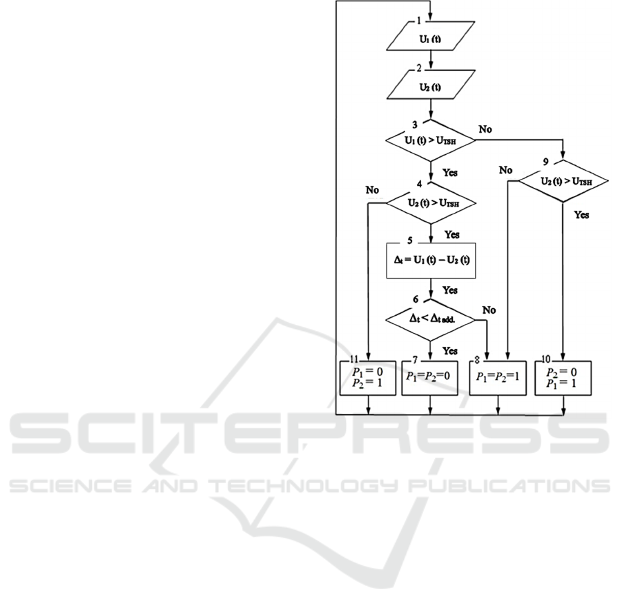
(algorithm) of decision-making (Figure 1) on the
vacancy/occupancy/breakage of the rail track in
conditions of changing the values of the insulation
resistance Z and the rail line.
Figure 1: Diagram of the decision-making structure of the
CTC.
Figure 1 shows the following values:
− the signal voltage at the output of the
demodulators of the TR of the first and second
coordinated TC, respectively, U
1
(t) and U
2
(t);
− the voltage of the shunt sensitivity threshold of
the TR of coordinated TC U
ST
(constant value);
− a value that takes into account the natural
variation of U
1 values
(t) and U
2
(t) under real
operating conditions– ∆
t
;
− the acceptable level of the value ∆
t
. – ∆
tACC
.
The conclusion about the possibility of the CTC
operation over time and the change in the insulation
resistance of the rail line is made taking into account
the difference approximation:
1. A preliminary check of inequalities is being
developed
U
1
(t) > U
ST
0 and U
2
(t) > U
ST
;
2. The correspondence is calculated in time
∆
t
= U
1
(t) – U
2
(t);
3. The value of ∆
t
is compared with the
established norms for a particular case with the
value of ∆
tACC
.
Coordinated Track Circuits
197
Let's define all existing combinations of values of
these calculations:
1. There is a solution. U
1
(t) > U
ST
, U
2
(t) > U
ST
, ∆
t
= U
1
(t) – U
2
(t) and ∆
t
< ∆
t ACC
– we are moving
along the path 1-2-3-4-5-6-7.
2. There is a solution. ∆
t
≥ ∆
t ACC
– we are moving
along the path 1-2-3-4-5-6-8.
3. There is a solution. U
1
(t) > U
ST
, U
2
(t) ≤ U
ST
–
we are moving along the path 1-2-3-4-11.
4. There is a solution. U
1
(t) ≤ U
ST
, U
2
(t) > U
ST
–
we are moving along the path 1-2-3-9-10.
5. There is a solution. U
1
(t) ≤ U
ST
, U
2
(t) ≤ U
ST
–
we are moving along the path 1-2-3-9-8.
The algorithm presented in Figure 1 assumes the
characteristic features of the functioning of
coordinated TC with a single TG:
− analysis of voltage values of signals U
1
(t) and
U
2
(t) in the TR demodulator of the coordinated
TC exercising control of the 1st and 2nd
adjacent rail sections of the track occurs in
symbols 1 and 2;
− 3,4: comparison of voltage values U
1
(t) and U
2
(t) respectively with threshold values of
sensitivity U
ST
in TR shunt mode of the TC (U
1
(t) > U
PS
and U
2
(t) > U
PS
) when exceeding U
1
(t) and U
2
(t) the values of U
ST
are compared
with the values of U
1
(t) and U
2
(t) between
themselves by means of calculations according
to the formula ∆
t
= U
1
(t) – U
2
(t), and if U
1
(t)
takes values greater than U
ST,
and U
2
(t) is
greater than or equal to U
ST
, then in the 11th
character a decision is made that the second
section of the rail track is occupied (P
1
= 0; P
2
= 1);
− symbol 6 is responsible for comparing the
values of the values of ∆
t
and ∆
t ACC
, necessary
to fulfill the conditions when controlling the
7th and 8th symbols:
− -∆
t
< ∆
tACC
both sections of the track control are
vacant (Р
1
= Р
2
= 0) (the decision is made in
symbol 7);
− -∆
t
≥ ∆
tACC
both sections of the track control are
occupied (P
1
= 1; P
2
= 1) (the decision is made
in symbol 8);
− The symbols 8 and 10 are controlled by the
symbol 9 in the case of:
− -U
2
(t) ≤ U
ST
both controlled sections of the
track are occupied (P
1
= 1; P
2
= 1) (symbol 8)
− -U
2
(t) > U
ST
the second of the controlled
sections is vacant, the first is occupied.
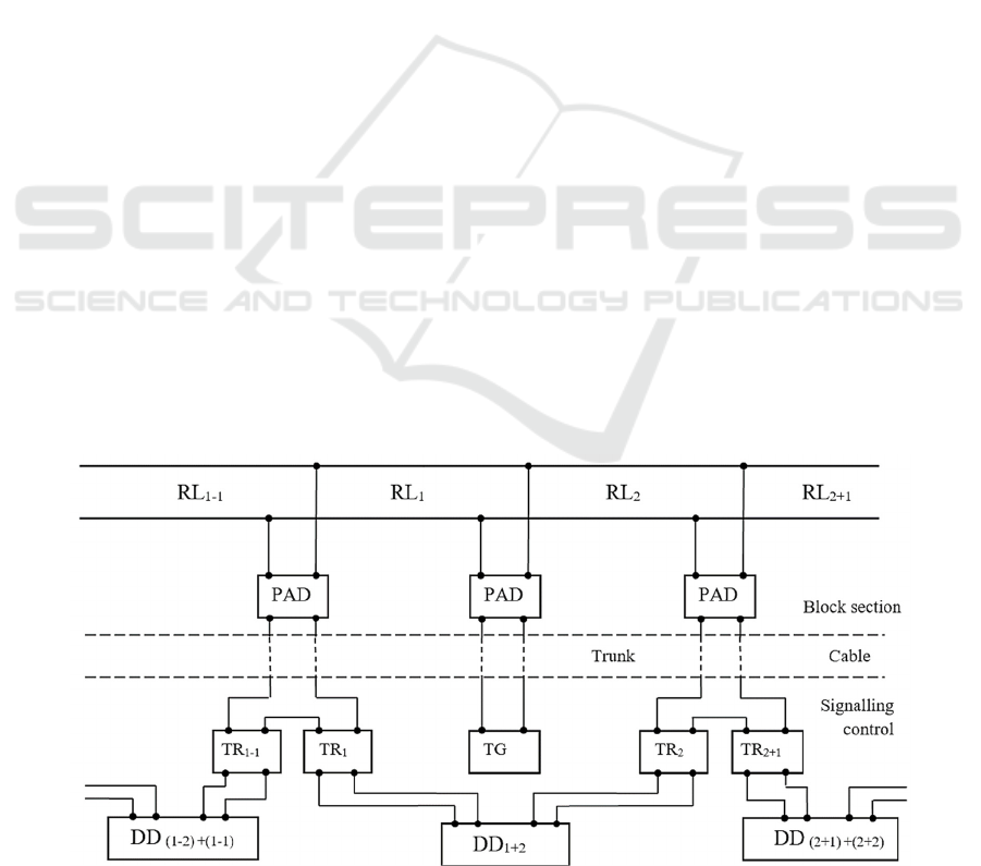
An electrical functional circuit based on and
implementing the algorithm (Figure 1) is shown in
Figure 2.
The picture shows:
− rail lines under the control of the first and
second sections of the track respectively – RL
1
and RL
2
;
− rail lines adjacent to the controlled sections of
the track – RL
1-1
and RL
2+1
;
− protection and alarm devices – PAD;
− track generator – TG;
− track receivers of the first and second CTC
respectively – TR
1
and TR
2
;
− track receivers of TC adjacent to CTC – TR
1-1
and TR
2+1
;
− decision-making device on the state of
controlled sections of the track – DD
1+2
;
− devices for making decisions (decision
devices) about the condition of the sections of
the track adjacent to the CTC– DD
(1-2)+(1-1)
and
DD
(2+1)+(2+2)
.
Figure 2: Electrical functional diagram of coordinated TC.
TLC2M 2022 - INTERNATIONAL SCIENTIFIC AND PRACTICAL CONFERENCE TLC2M TRANSPORT: LOGISTICS,
CONSTRUCTION, MAINTENANCE, MANAGEMENT
198
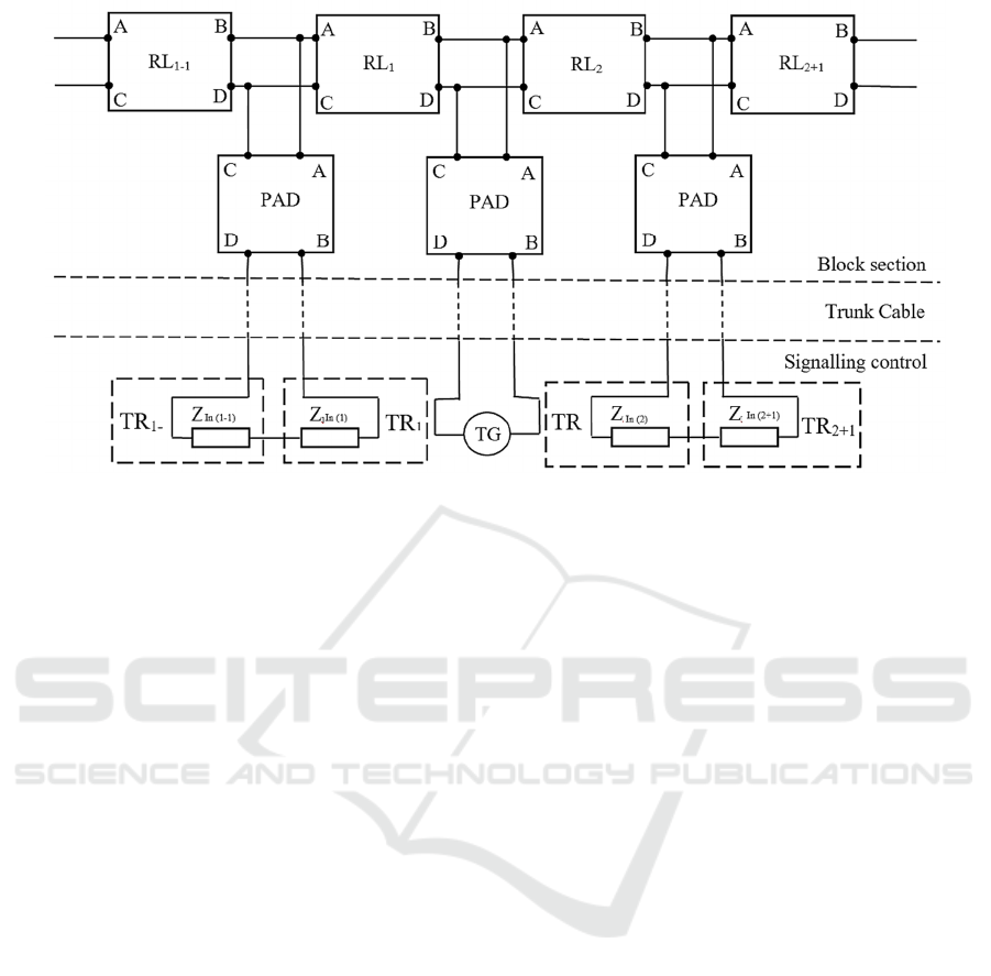
Figure 3: Replacement scheme of coordinated TC.
The device, which performs the control function
when deciding on the state of the regulated sections
of the rail-bed DD
1+2
, works based on the algorithm,
the block diagram is shown in Figure 1.
In accordance with the electrical functional
scheme, which is shown in Figure 2, a single model
of the replacement circuit for coordinated TC was
compiled (Figure 3), taking into account the concepts
of the theory of track circuits and the simulation
apparatus, it is already possible to develop a
simulation model of the coordinated TC.
3 CONCLUSIONS
Summing up, we can say that in order to establish and
assess how effective the TC is, it is necessary to
determine the ability of the track receiver to guarantee
the reception and processing of signals with a set level
of reliability under the worst operating conditions. In
addition to this, the numerical coefficient for
evaluating the efficiency of the system makes it
possible to analyze the operation and functionality of
the track circuit in different operating modes and with
different inputs, as well as, if necessary, compare the
TC with each other.
REFERENCES
Akhmadulin, F. R., 2006. Rail line status control by the
method of paired coupling. Materials of the 3rd
International Scientific and Practical Conference
«Actual problems of railway transport development»,
pp. 48-58.
Akhmadulin, F. R., 2007. Balanced track circuits. In
collection of scientific papers dedicated to the 170th
anniversary of Russian railways «Young scientists –
transport», pp. 12-14.
Akhmadulin, F. R., 2008. Nonconjugated correlative track
circuits. Scientific and technical journal «Transport of
the Urals». 4(19). pp. 67-69.
Akhmadulin, F. R., 2009. The method of control of the
correlative track circuit with paired coupling. Scientific
and Technical Journal «Bulletin of transport of the
Volga region». 4(20), pp. 31-34.
Akhmadulin, F. R., 2010. The method of monitoring the rail
line status. Materials of the II International Scientific
and Practical Conference «Science and education for
transport, dedicated to the 110th anniversary of
transport education in the Saratov region», pp. 73-76.
Akhmadulin, F. R., 2011. Nonconjugated correlative track
circuits with the control method at different input
resistances at the ends of the rail line. Materials of
scientific and technical conf. «Transport of the XXI
century: research, innovation, infrastructure,
dedicated to the 55th anniversary of USUPS: in 2
volumes», 97(180), 1, pp. 740-744.
Akhmadulin, F. R., 2020. Conjugated correlative track
circuits. Materials of the International Scientific and
Practical Conference «Scientific and practical
research: applied sciences», 3-1(38), pp. 4-6.
Pat. No. 2273583 of the Russian Federation, IPC B 61 L
23/16. A way to control the vacancy of the rail line.
Polevoy Yu.I., Polevaya L.V., Troshina M.V. (RF). –
No.2004117666/11; Announced 09.06.2004; Publ.
10.04.06. Byul. No. 10, Priority 09.06.2004, (RF). – 5
p.: ill.
Coordinated Track Circuits
199
