
An Apparatus for Monitoring Sea Ice Thickness Based on Coplanar
Multi-Electrode Capacitance Sensor
Ling Zhang and Yinke Dou
College of Electric and Power Engineering, Taiyuan University of Technology,No.79 West Sree Yinze,Taiyuant,
shanxi,China
{zhangling,douyinke}@tyut.edu.cn
Keywords: Coplanar, Multi-electrode capacitance, Sea ice, Antarctic.
Abstract: This study describes an apparatus for in situ measurement of centimeter-accurate changes in the sea ice
thickness in Antarctica. The apparatus consists of a rod-shaped measurement sensor based on coplanar
multi-electrode capacitance sensing technology. In use, it is vertically installed into the sea ice to realize
automatic monitoring of increases in sea ice thickness. It is suitable for monitoring fixed measurement sites
on ice that are not deformed. The apparatus presented was tested on landfast ice and ice cap near China’s
Zhongshan Station (East Antarctica) for approximately 6 months during the austral autumn and winter. Data
on the coastal sea ice thickness at the Zhongshan Station for 6 months was obtained. An analysis of the data
verifies the reliability and accuracy of the apparatus for monitoring Antarctic sea ice. Application
experiments prove that the apparatus can realize the automatic monitoring of sea ice thickness on fixed sites
and provides a new method of monitoring sea ice thickness.
1 INTRODUCTION
Sea ice thickness directly affects the thermodynamic
interaction of the atmosphere and marine
environments. It has long been considered a key
indicator reflecting climate change in polar regions.
However, little is known about ice thickness
changes. Sea ice plays an important role in the
global radiation balance and global climate due to its
smooth surface and the accumulated snow thereon.
Moreover, continuous, real-time automatic
monitoring of ice thickness on fixed sites is a
difficult problem in ice thickness detection
technology. At present, four methods are mainly
employed in sea ice thickness observation. These
are, manual hole-drilling measurements, remote
sensing measurements, sonar measurements, and
airborne (ship) electromagnetic sensing
measurements.
Manual hole-drilling was the earliest ice
thickness measurement used. The method is highly
accurate, very reliable, and has been widely used.
However, it cannot realize fixed-site real-time
measurement. Moreover, it requires high labor
intensity and shows low efficiency. Thus, it is
merely used to make measurements at key points. In
addition, this method cannot be used during ice
forming and thawing periods for the sake of safety.
Remote sensing refers to the measurement of a
wide range of ice structures using measurement
devices carried by satellites Satellite remote
sensing contributes much to the monitoring of a
wide range of ice and is widely utilized. However,
due to the satellite’s altitude, picture resolution is
low. Therefore, this method can only be used to
obtain characteristic ice information on a large scale.
It is not capable of acquiring ice parameters on
medium and smaller scales. Furthermore, it is
relatively easily influenced by weather.
In sonar measurement, a high frequency
transducer is used to emit different forms of signals
and the time-delay between the reflected signals
from the ice-air and ice-water interfaces detected.
The ice thickness can then be calculated from the
time difference between the echo signals from the
two interfaces and the sound velocity in the ice in
the measurement area. This method shows the
optimum under-ice resolution and can avoid the
influence of ice properties. However, it is only able
to detect the ice thickness below the waterline of the
ice layer.
Airborne (ship) radar measurements began to be
used in sea ice observation in the middle 1980s. In
Zhang, L. and Dou, Y.
An Apparatus for Monitoring Sea Ice Thickness Based on Coplanar Multi-Electrode Capacitance Sensor.
In 3rd International Conference on Electromechanical Control Technology and Transportation (ICECTT 2018), pages 467-475
ISBN: 978-989-758-312-4
Copyright © 2018 by SCITEPRESS – Science and Technology Publications, Lda. All r ights reserved
467

this method, the ice thickness is obtained by
analyzing electromagnetic echo signals and
calculating the distance between the upper and lower
surfaces of the ice. The main commercial products
used include the EM-31 ice and snow detector, etc.
The method can be directly applied in moving
situations and can collect a large amount of data in a
short period of time without damage to the ice.
Thus, the influences of summer and device
installation on the ice melting rate are reduced.
However, in this method, the contours or ‘ups and
downs’ of the ice surface are all included in the
bottom surface morphology.
The members of our team have developed a
fixed-site magnetostrictive sea ice thickness
measurement device. The device was adopted to
monitor the sea ice near Zhongshan Station for more
than half a year and is capable of monitoring sea ice
thickness to a precision of ±2 mm. Unfortunately,
due to certain factors, such as the inability of the
power supply used to provide the long-term,
unattended mechanical power the system requires,
the equipment is still at present in a state of
improvement. Therefore, a new device is designed
in the current study to measure changes in the
snow/ice thickness at fixed sites. It aims to monitor
the sea ice thickness in time to a precision of 1 cm.
Moreover, the power consumption of its power
supply is low. A 12 V spirally-wound lead acid
battery with a capacity of 80 Ah can ensure normal
working of the whole device set for one year. In
addition, the whole device set has a low cost and is
suitable for being laid on a large area of sea ice. This
device was applied to the ice surface and ice cap
near Zhongshan Station.
This study first introduces the basic principles
involved, as well as the design and production
process used to construct the system for ice
thickness detection by coplanar multi-electrode
capacitance sensors and corresponding system.
Then, it discusses application of this apparatus in the
detection tests carried out on the sea ice near
Zhongshan Station. The accuracy of the apparatus is
also analyzed. Finally, the in situ application and
problems encountered with it are discussed and
solutions and improvement measures for these
problems outlined.
2 BASIC PRINCIPLES
Brine and ice have contrasting electrical properties
in-terms of both charge transport efficiency and
charge transport mechanics. In brine, the differential
movement of the abundant free salt ions constitutes
an electrical current, while conduction in ice is
facilitated by imperfections in the crystalline
lattice.These defects propagate through the structure
by reorientation of molecules and reordering of
bonds, a phenomenon known as protonic
conduction. Pure ice is a poor electrical conductor
because the defect concentration is low, while any
brine included in the ice has a high conductivity.
Electrical methods can be performed on the ice
in-situ and they offer the possibility of automated
sea ice monitoring.The measurement of ice
thickness using coplanar capacitance sensors based
on the different permittivities of sea ice and water.
The basic principle of this apparatus centers on the
capacitance end effects of the capacitance sensor.
(a) (b)
Figure 1: Electric field model of a multi-electrode
capacitance
(a) The basic working principle of the
coplanar capacitance sensor
1-- electric field between the electrode plates .2,4--
exciting electrode plate .3--receiving electrode plates
(b) illustrates the field distribution in the layers
of the underlying medium.
Figure. 1(a) illustrates the basic working
principle of the coplanar capacitance sensor. The
apparatus is composed of exciting and receiving
electrode plates. The plates are isolated by grounded
shield layers. The electric field variation between
the exciting and receiving electrode plates depends
on the ice thickness and so the latter may be
measured indirectly. In 1969, Noltingk first
proposed a high-precision measurement system
based on the end effects of coplanar capacitance. In
addition, he implemented the design structures of
two sensors, namely, a giant coplanar capacitance
sensor and an annular coplanar capacitance sensor.
The two sensors both utilized the capacitance end
effect to measure micro-distances. In 1976,
Noltingk, Nye and Turner presented a mathematical
analysis of the coplanar capacitance sensor for polar
ICECTT 2018 - 3rd International Conference on Electromechanical Control Technology and Transportation
468

plates that are rectangular in structure. In 1993, Luo
and Chen mathematically analyzed the annular
coplanar capacitance sensor and established the
corresponding mathematical model. In more recent
years, coplanar capacitance sensors have been
widely used for material thickness measurement(
J.Graham,2000 ) moisture or humidity
measurement, etc. Sundara-Rajan et al. used
coplanar capacitance to determine the moisture
content in paper. A. S. Zyuzin et al. adopted
coplanar capacitance to detect the moisture content
in food, such as biscuits, etc. TianMing Chen
employed coplanar capacitance to perform
nondestructive inspection of multi-layer structures.
Nassr also used coplanar capacitance to inspect the
moisture content of a medium with complex
structure.
Figure. 1(b) shows the electric field distribution
produced in the media layers beneath the sensor.
Since the electric field strength decays exponentially
with the thickness of the measured medium, the
permittivity of the medium closer to the fixed
electrode surfaces has a larger impact on the
capacitance between the coplanar electrodes. In the
cross-section shown in Fig. 1(b), a coplanar sensor
is created by two electrodes of width s spaced 2g
apart on two substrate layers of heights h1 and h2
(from the upper surface) and dielectric permittivities
r
ε
, respectively. In the analysis, the electrode strips
are assumed to have zero thickness and infinite
conductivity. Also, the strip length l is larger than
the width (l > s) to avoid end effects. The
capacitance between the two electrodes due to the
substrate layers is given in closed form as
'
0
0
0
()
()
r
Kk
C
Kk
εε
=
, (1)
where K(k) is the complete integral function, ε0
is the vacuum permittivity (F m–1), and
0
k
and
'
0
k
are functions of s and g. They are given by
0
g
k
s
g
=
+
, and
'2
00
1kk=−
.
It can be seen from Eq. (1) that the variation in
the capacitance of the coplanar electrodes shows a
certain functional relationship with the permittivity
of the medium close to the electrode. Since water,
ice, and air present different permittivities at a
certain environmental temperature, a plurality of
electrodes can be installed in parallel in the same
plane to constitute a coplanar multi-electrode
capacitance sensor. Such a sensor can then be
installed vertically in the ice and the water under the
ice. Since the media contacting the electrodes are
ice, water, or air, the capacitances between each
electrode and adjacent electrodes are different. Thus
the vertical measurement of ice thickness can be
realized.
The coplanar multi-electrode capacitance ice
thickness measurement is based on the model in
Figure1. Through the contact made with different
media (such as ice and water) the exciting metal
electrode is affected and the electric field around the
metal electrode is changed. The capacitance of the
metal electrode is thereby altered. It is assumed that
C3 is the capacitance composed by one single
capacitance electrode plate (A in the diagram) and
its adjacent grounding electrode plates. The air’s
permittivity is ε
0
, ε
r
is the dielectric coefficient of
the medium, and A is the electrode plate area. When
ε
r
fluctuates, the capacitances C1, C2, and C3 are
changed. Since the three capacitances are in parallel
in the circuit, the total variation of the capacitance
Cx can be found from Cx = C1 + C2 + C3. In the
equivalent circuit shown in Figure 2, the voltage at
point A is proportional to 1/Cx. The voltage detected
at point B is first transformed into a direct current
(DC) through the internal detector and low-pass
filter of the device. Then the DC signal is processed
by the external microcontroller bearing an analog to
digital (A/D) converter. For example, a single chip
microcomputer (SCM) can be used. The
microcontroller is capable of treating multiple
signals and can thus achieve the goal of the
measurement.
Figure 2: The equivalent circuit for medium measurement
using the capacitance of one coplanar electrode.
The principle underlying ice thickness
measurement using a coplanar multi-electrode
capacitance sensor and corresponding system is
shown in Figure 3. Considering the requirements for
the actual measurement of sea ice, the ice thickness
sensor is designed to be a plurality of electrodes.
More than 100 electrodes are used, which are
uniformly arranged in the same plane (each
electrode measures 1 cm). The detection principle is
AC
R
C1
C2
C3
A
B
An Apparatus for Monitoring Sea Ice Thickness Based on Coplanar Multi-Electrode Capacitance Sensor
469
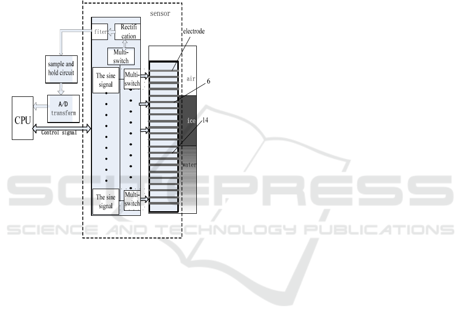
as follows. The control instrument of the SCM sends
control signals to the sensor to open its multi-switch.
Thus, the sinusoidal signal of first measurement
circuit unit is connected with the first electrode at
the top of the sensor, while the other electrodes are
connected to earth. Then , the sinusoidal signal
flows back to sine power supply to generate a
ground electrode signal by the divider resistance, the
capacitance formed by the metal electrode and the
rest of the electrodes around, and the capacitance
formed by the electrode and the medium.
Figure 3: A schematic diagram illustrating the principle of
the measurement system
Afterwards, the ground electrode signal sends
voltage on the electrode to the A/D input port of the
SCM after transferring the voltage into a DC signal
by rectification, and filtering circuit in sequence.
The SCM collects and saves these voltage signals.
Then the SCM releases a control signal to get
connected with the second electrode from the top.
The voltage on the second electrode is measured,
and so on. Since the permittivities of air, water, and
ice are different at particular environmental
temperatures, the capacitances between each
electrode and its adjacent electrodes are different.
The difference in capacitance is expressed as a
variation in the voltage. Therefore, a set of voltage
data is obtained by measuring, in order, the voltages
on each of the electrodes using the SCM. According
to the voltage jumps on the electrodes, it can be
judged which electrode is surrounded by ice, which
is surrounded by water, and which is surrounded by
air. In this way, the ice thickness can be determined.
The SCM collects data at fixed times separated by a
certain time interval. Finally, it periodically sends
the data acquired to a computer terminal by wireless
transmission.
The coplanar multi-electrode device and its
system consist of two parts, namely, the sensor itself
and its accompanying measuring instrument. The
sensor mainly consists of the metal electrode
sensors, multi-switches, sine signal generators, a
rectifier, and a filter. Part of the circuit board of the
sensor is sealed by encasing it together with the
metal capacitance electrodes. The measuring
instrument is composed of the SCM, the A/D
conversion circuit, the data storage circuit, the GSM
modem, etc. In the circuit design, the circuits
generated by each sine wave generator are combined
with a rectification circuit to form a circuit module.
Each module contains 7 electrodes at most to avoid
parasitic capacitance on the electrodes caused by
wires on the circuit board that are too long. The
SCM control circuit mainly controls the sensor
circuits and thereby detects the ice thickness. The
circuit board of the measuring instrument containing
the SCM is placed on one end of the sensor. It is
insulated from the electrodes by hard plastic sheets.
The surface of the coplanar multi-electrode sensor is
sealed using insulating materials to prevent direct
contact of the capacitance electrodes with the ice
and water. Using the SCM control circuit and
wireless transmission module on the sensor,
automatic unattended remote monitoring of the ice
thickness can be achieved.
Considering that the ice thickness measurement
depends mainly on the measurement and judgment
of the positions of the interfaces between air and ice,
and ice and water, the whole apparatus is generally
chosen to be a long rod shape. A large number of
experiments and comprehensive data results show
that the sensing effect is optimum using 0.3 mm
thick copper foil for the electrode material.
Electrodes are placed every 1 cm, so that the
measuring precision of the sensor is kept to the
centimeter level. In the experiment reported here,
copper foils measuring 6 mm and 4 mm in width
and 15 cm in length are used for the metal electrodes
(the thickness is 0.3 mm, as already said).
ICECTT 2018 - 3rd International Conference on Electromechanical Control Technology and Transportation
470
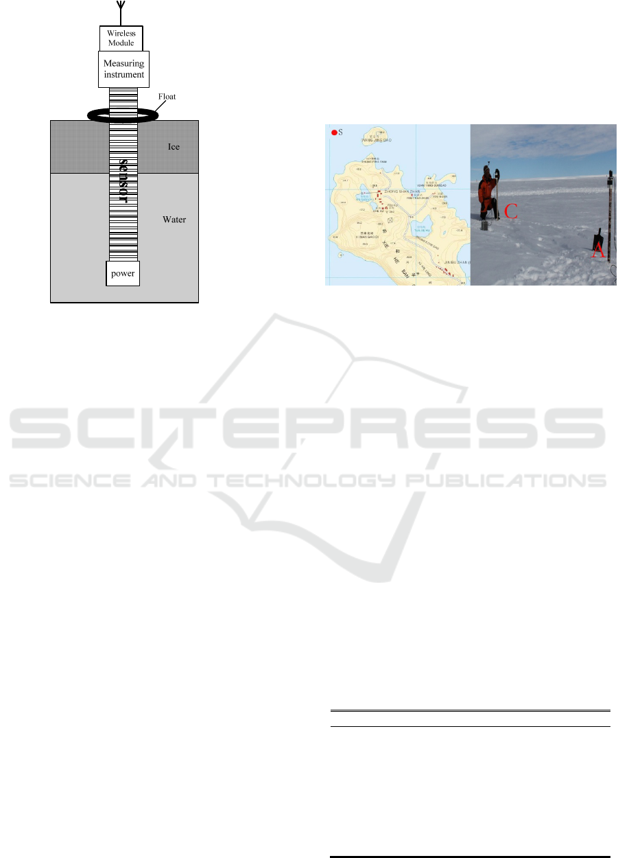
Figure 4: Installation diagram of the sensor in
the ice.
Experimental results also suggest that the wider
the copper foil strip is, the lower the voltage on the
electrode, and the larger the capacitance of the
copper strip is. With increasing space between metal
electrodes, the voltage on the metal electrode
gradually grows until it reaches a certain value. This
phenomenon indicates that an increase in the space
between electrodes can reduce the capacitance of
electrodes, however, this reduction will not continue
when a certain value is reached. To better seal the
electrodes, we molded a thin layer of insulating
epoxy resin material on the bottom of grinding
apparatus of PVC material in a selected shape and
volume before laying out the electrodes. Generally,
the epoxy resin layer is around 2 mm thick. When
the epoxy resin had completely solidified, copper
foil electrodes were laid on the surface of the thin
epoxy resin layer at an interval of 4 mm and 1 cm
for one electrode. The installation diagram of the
sensor and the corresponding measuring system for
measuring ice thickness is shown in Figure 4.
3 IN SITU EXPERIMENTS
3.1 In Situ Environment
In March 15, 2016, researchers installed the two sets
of apparatus into the sea ice near Zhongshan station
(specific location 69°22′05.1″ S, 76°21′51.3″ E). The
photograph on the left in Figure 5 shows the in situ
installation of the two sets of measuring devices.
Points A and C are the sites where the measurement
devices are installed. The horizontal distance
between the two sites is 20 m. The right-hand
photograph in Figure 5 presents the in situ
installation of the sensor at point A. At installation,
the in situ snow depth was only 1 cm thick. The
installation steps are indicated below.
Figure 5: In situ installation pictures.
A wooden strip fixed 8 cm below the top of the
sensor was used as a float. A hole was drilled in the
ice’s surface using a hand-cranking ice driller. Then,
the ice thickness around the ice hole was manually
measured using a tape measure and the ice
suspension height was determined using a ruler. The
rod-shaped sensor was vertically inserted into this
ice hole until the float was stuck on the ice surface.
Then the ice hole was filled using ice flakes or snow
to keep the apparatus vertical. After the power
supply was switched on, the apparatus started to
work. Finally, a few holes were drilled in the ice
surface. The storage battery sealed using insulating
material was fixed using wooden rods and ropes to
prevent the wind blowing it away. The initial
number of electrodes of the measurement sensor
exposed to the air at site A was 8, that is, the top
sensor is 8 cm from the ice surface in site A. The top
sensor at site C was 10 cm from the ice surface
initially.
Table 1: The in situ conditions of the measurement
device.
Ite
m
Site A Site C
Initial snow
thickness (cm)
0.2 0.2
Initial ice
thickness (cm)
26 27
Initial ice
suspension (cm)
4 5
Lowest
temperature (°C)
–33.8
Highest 0.1
An Apparatus for Monitoring Sea Ice Thickness Based on Coplanar Multi-Electrode Capacitance Sensor
471
temperature (°C)
Maximum
snowfall
(
cm
)
48
Maximum wind
s
p
eed
(
m/s
)
40.7
From March 16, 2016 to August 31, 2016, the
lowest and highest temperatures of the sea area at
the two devices were –33.8°C and 0.1°C,
respectively, according to in situ detection. During
the monitoring period, the monitored sea area
experienced many periods of snowfall, and the
highest snow thickness was 31 cm. The sensor
became completely covered by snow, but in a short
period of time most of the snow was blown away by
wind. The maximum wind speed in the detection
area was 40.7 m/s during this period. Table 1
describes the field environment of the detected sea
area during the monitoring period.
3.2 Experimental Results
From March 16 to August 31 in 2016, the southern
region of Australia was in autumn and winter and
Antarctica was in winter. Throughout this time
period, the two measurement devices worked
normally on the sea ice near Zhongshan Station for a
total of 168 days. Measurement was conducted 3
times a day. Thus, 504 groups of data were obtained
from each measurement device. In the experiment,
the Iridium Satellite system’s remote data delivering
service was employed for a week of the experiment.
The rest of the data was collected directly by field
researchers who read the SD memory cards in the
apparatuses at fixed time points.
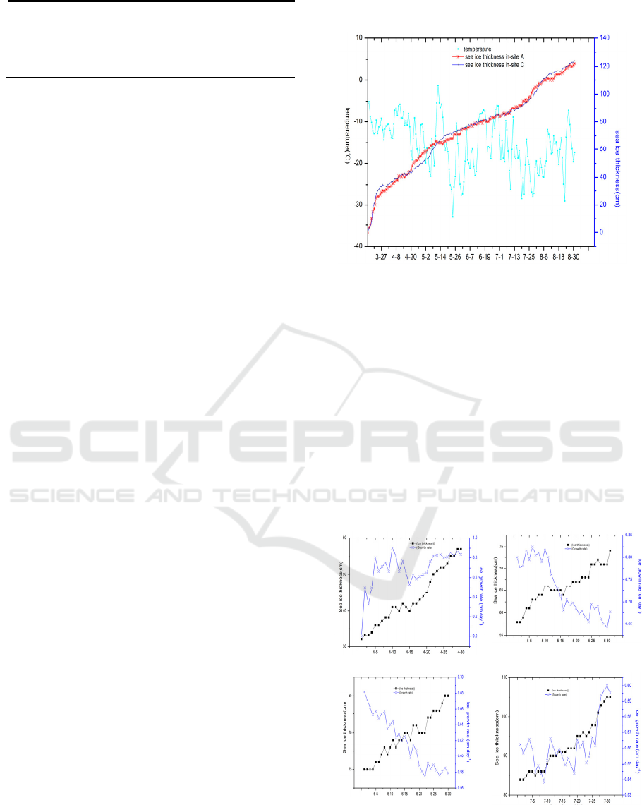
By preliminarily analyzing the data acquired, it
was found that the maximum daily growth in ice
thickness was 3 cm. We employed the data collected
at 0:00 every day and obtained 168 sets of data. The
ice thickness and daily temperature variation curves
in the detected sea area acquired by the two
measurement devices over the 168 days are shown
in Figure 6. In this figure, the ice thickness variation
at sites A and C are basically consistent. The ice
thickness data detected at the two sites from June to
July are very close. In the two periods with rapid
growth (April 20–May 15 and in August), the ice
thicknesses show larger differences. From March 16
(when the two sets of measurement devices were
installed) to March 28, ice thickness grew from 0 cm
to around 30 cm. (Since the sensors were initially
installed in ice holes with diameters of 10 cm drilled
by the ice driller, the ice thickness grew from 0 cm.
To March 28, the ice thickness in the hole that the
measurement devices were installed in had been
consistent with the surrounding ice thickness.
Figure 6: The ice thickness variation at sites A and C
and the daily mean temperature curve.
In this experiment, the data collected after March
28 is used in the calculation of sea ice growth rate.
That is to say, the sea ice thickness measured by the
two sets of devices from March 16 to March 28
cannot reflect the natural growth condition of sea ice
at the detection sites. Thus, the natural growth rate
of the sea ice is calculated when the sea ice
thickness at the detection sites agreed with that due
to natural growth on March 28. The calculation
formula for the sea ice growth rate is where H
i
is the
ice thickness, ti is the measurement time, and ti+1 is
the next measurement time .
(a) (b)
(c) (d)
Figure 7: Graphs showing the variation in sea ice
thickness and ice growth rate.
ICECTT 2018 - 3rd International Conference on Electromechanical Control Technology and Transportation
472
According to this formula, the daily mean
growth rates of the sea ice at sites A and C of the
detection area are 0.618 cm day–1 and 0.498 cm
day–1, respectively. The maximum sea ice thickness
growth rate at site A is observed on April to May 13,
with a value of 0.83 cm day–1, as shown in
Figure 7(a) and 7(b). The minimum sea ice thickness
growth rate at site A is found on June 25 to July 25,
with a value of 0.54cm day–1, as shown in
Figure 7(c) and 7(d).
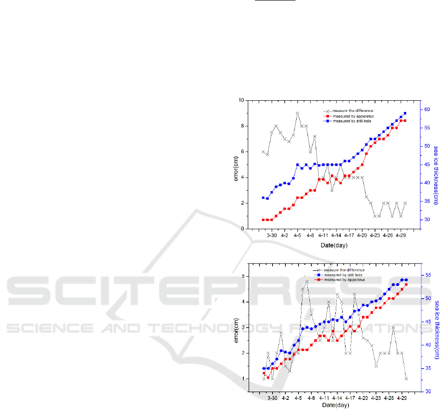
3.3 Precision Analysis
While monitoring the sea ice, the sea ice thicknesses
at sites A and C were also measured manually using
the hole-drilling method. Providing the weather
permitted, these measurements were carried out
once a day. Figure 8(a) and 8(b) show the sea ice
thickness variation at sites A and C, respectively, as
detected by the measurement device and manually.
It can be seen from Fig. 9 that the device
measurement results are all smaller than those
obtained by manual hole-drilling at both sites A and
C. That is, there is a certain difference between the
sea ice thickness results as measured by the two
measuring devices and by the manual hole-drilling
method. This is attributed to the fact that the
skeleton ice (flocculent ice) on the contacting part
of the sea ice and sea water has a certain thickness.
In a manual hole-drilling measurement, the sea ice
thickness is measured using a tape. Thus, the
thickness of the skeleton ice is included in it.
However, with the device measurements, skeleton
ice is recognized as sea water by the capacitance
sensing electrodes due to its larger water content.
Therefore, the sea ice thickness measured by the
device is smaller than that obtained by the manual
hole-drilling method. The difference is relatively
large during March 28 to April 20. The maximum
value of the difference at site A reaches 9 cm. By in
situ inspection, we conclude that this was because
the ice in the ice hole in which the device was
installed in did not become frozen to the same
thickness as the surrounding ice. The minimum
difference value is 1 cm. The maximum and
minimum difference values at site C are 5 cm and 1
cm, respectively. The difference tends to be a stable
1–2 cm after April 20. Therefore, the device
measurement data and manual hole-drilling
measurement data from April 20 to April 30 are
used for analysis. The deviation D in the device
measurement can be calculated according to the
following formula
%100
d
d-e
zm
zmzm
×=D (2)
where, e
zm
is the mean ice thickness measured by
the device in the ten days, and d
zm
is the mean sea
ice thickness obtained by the manual hole-drilling
measurement. By calculation, it is found that this
formula is consistent with the work of Kovacs et al.
in 1996 and Haas et al. in 1997.The relative
deviation of apparatus is thus –3.5%.
(a)
(b)
Figure 8: Comparison of the data obtained using the
measurement device and by manual hole-drilling at (a)
site A, and (b) site C.
4 PROBLEMS AND DISCUSSION
The sensor proposed in this study was applied to
detect the sea ice thickness near Zhongshan Station.
However, the sensor is only 1.4 m long, while the
sea ice thickness in the detection area can reach up
to 1.5 m (maximum depth). Moreover, the two
sensors were exposed above the sea surface by 8 and
10 cm. This means that their under-ice measurement
An Apparatus for Monitoring Sea Ice Thickness Based on Coplanar Multi-Electrode Capacitance Sensor
473

lengths were 1.32 m and 1.30 m, respectively.
Therefore, when the sea ice thickness exceeds 1.30
m, the two sensors cannot be used to accurately
measure the sea ice thickness. Thus, the experiment
was terminated when the sea ice thickness exceeded
1.25 m (at the end of August). In addition, during the
6 months of the application, the snowfall thickness
on the sea ice surface was more than 10 cm on May
27 and July 3. Thus the data between the air and ice
snow surface, and snow surface and ice surface
cannot be correctly judged by the sensors.
This study proposes a new apparatus for
measuring ice thickness that uses capacitance.
According to the different dielectric properties of
air, ice, and water, this apparatus determines the air
layer, ice layer, and under-ice water layer
thicknesses using a layered measurement method
and coplanar multi-electrode capacitance sensor.
Moreover, it can also be applied to automatic
real-time monitoring of sea ice thickness in polar
regions and, by extension, to automatic monitoring
of river ice thickness in rivers (or reservoirs) in
winter.
Several problems arise in the application of the
coplanar multi-electrode capacitance ice thickness
sensor:1) Since electrodes are installed in different
positions in the sensor, the influence of the adjacent
electrodes on an electrode is different. This
phenomenon results in different voltages being
detected by two electrodes although the surrounding
medium is the same. This is an inherent problem
arising from the nature of the sensor. The mutual
interference between electrodes can be reduced by
shielding measures, etc., but cannot be completely
eliminated.2) Environmental temperature has a
certain influence on the capacitance presented by the
coplanar electrodes. For electrodes of the same size,
the lower the temperature is, the smaller is the
capacitance formed by one electrode with an
adjacent electrode. As the temperature in the ice
layer varies from top to bottom, the capacitances of
the metal electrodes at the same site are different for
different parts of the ice layer. In this way, the
medium around the electrode may be easily
misjudged. This problem can be solved using
temperature compensation, that is, the
environmental temperature around the electrode is
detected by setting a certain number of temperature
sensors. When the temperature changes, the
electrode capacitance can then be compensated
using a hardware circuit.3) Power supply problems.
Since the ice thickness measurement system is
operated in a low temperature environment, the
power consumption of the electronic components is
increased. Thus, it is a requirement that the whole
system must be provided with a reliable power
supply. In this study, a storage battery with a
relatively large capacity is employed. Moreover, it is
sealed by encasing and placed in the lower part of
the sensor. In this way, the storage battery can be
constantly immersed in river or sea water. As river
water has a temperature around 0°C and sea water
temperature is around –3°C, battery power loss will
not be induced by an overly-low temperature.
5 CONCLUSIONS
The coplanar multi-electrode capacitance ice
thickness detecting sensor and its system is still
currently in a laboratory research and field trial
stage. To realize fixed-site automatic monitoring of
ice thickness, the following problems need to be
further studied and addressed.
First, The dielectric properties of sea ice. Sea ice
has complex structural forms, e.g. pure ice form,
ice-brine form, etc . Therefore, it exhibits different
dielectric properties at the same temperature. This
situation can induce misjudgment of the ice medium
when using the capacitance electrode. Thus, a large
amount of laboratory experiments are needed to
measure the dielectric property of sea ice in its
different forms and to establish a dielectric database
of the ice’s properties as a function of temperature
and form. The results obtained can provide a
database for accurate measurements with the
capacitance electrode.
Second,The structure of the sensor. This problem
is mainly concerned with the size of the coplanar
electrode and the space between electrodes. It
directly affects the measurement precision of the
sensor. Thus, if measurement precision is required to
be improved to ±3 mm, the width of the sensor’s
electrodes can only be 2 mm at most, and the space
width can be at most 1 mm. Moreover, whether the
setting is the optimal plan or not needs to be verified
via simulation. That is, the optimization of the
sensor structure needs to be realized by software
simulation.
In conclusion, an ice thickness sensor based on
coplanar multi-electrode capacitance has achieved
preliminary success in a laboratory study and field
experiment. After the problems above are solved,
the system will be considerably improved. Using the
system, it is feasible to measure the thickness of
river and sea ice at fixed sites. The ice thickness data
thus obtained can subsequently provide reliable data
for research on the thermodynamics of the ice.
ICECTT 2018 - 3rd International Conference on Electromechanical Control Technology and Transportation
474

ACKNOWLEDGMENTS
We are grateful to the Chinese Arctic and Antarctic
Administration for its logistic support during our
experiment; to Mr. Zhao jiecheng and Mr. Han
desheng,for their field-work support; to the
Meteorological Office of Zhongshan Station for
providing meteorological data. Three anonymous
reviewers are thanked for their comments, which
considerably improved this work.
REFERENCES
Meier,W., Stroeve, J., Fetterer, F.,Knowles, K.,2005.
Reductions in arctic sea ice cover no longer limited to
summer. Eos, Transactions of the American
Geophysical Society .v86, p3-26;
Stroeve, J., Serreze, M.C., Fetterer, F., Arbetter, T.,
Meier,W., Maslanik, J., Knowles, K., 2005. Tracking
the Arctic's shrinking ice cover; another extreme
September sea ice minimum in 2004. Geophysical
Research Letters 32, L04501.
Sturm, Matthew; Perovich, Donald K.; Serreze, Mark C.
Meltdown in the North, October 2003, Scientific
American, v289, n4, p60-67;
Perovich, Donald K.; Stroeve, Julienne C. ;
Richter-Menge, Jackie,al.,et, November 2006, Snow
depth and ice thickness measurements from the
Beaufort and Chukchi Seas collected during the
AMSR-Ice03 Campaign. Transactions on Geoscience
and Remote Sensing, v 44, n11, p3009-3019;
Richter-Menge, Jacqueline; Sonntag, John G..al,.et,
2012,A first assessment of Ice Bridge Snow and Ice
thickness data over arctic sea ice. IEEE Transactions
on Geoscience and Remote Sensing, v50, n6,
p2098-2111;
Rothrock, D.A.; Yu, Y.; Maykut, G.A.. December 1,
1999,Thinning of the Arctic sea-ice cover,
Geophysical Research Letters, v26, n23, p3469-3472;
P. Wadhams.2009,sea ice. Reference Module in Earth
Systems and Environmental Sciences,p141-158;
Kovacs, Austin; Valleau, N.C.; Holladay,
J.Scott ,Airborne electromagnetic sounding of sea ice
thickness and sub-ice bathymetry. Oct 1987, Cold
Regions Science and Technology, v14, n3, p289-311;
Haas, Christian1; Lobach, John2; al.,et, March
2009,Helicopter-borne measurements of sea ice
thickness, using a small and lightweight, digital EM
system, Journal of Applied Geophysics,
v67,n3,p234-241;
Holladay, J.S.; Rossiter, J.R. Airborne measurement of sea
ice thickness using electromagnetic induction during
LIMEX 89, 1990, Proceedings of the International
Offshore Mechanics and Arctic Engineering
Symposium, v4, p309-315;
Ruibo lei,Zhijun,li,et al,A New Apparatus for Monitoring
Sea Ice Thickness Based on the Magnetostrictive
-Delay-Line Principle. April 2009, Journal of
atmospheric and oceanic technology,v26 ,p818-827;
V. Petrenko and R. Whitworth, Physics of Ice ,Oxford
University Press, New York, 1999.
B.E.Noltingk,A novel proximity gauge[J],Journal of
scientific instruments,1969,v22(2):p356-360;
B.E.Noltingk,A.E.T.Nye,H.J.Turner,Theory and
application of a proximity gauge using fringing
capacitance[C],IN
Proc.ACTAIMEKO,1976,p537-549;
R.C.Luo,Z.H.Chen,Modeling and implementation of
innovative micro proximity sensor using
micromachining technology[C],IEEE/RSJ international
conference on Intelligent Robots and System
Yokohama,Japan,1993:p1709-1716;
J.Graham,M.Kryzeminski,Z.Popovic,Capacitance based
scanner for thickness mapping of thin dielectric
films[J],Review of Scientific
Instruments,2000,v71(5):p2219-2223;
K.Sundara-Rajan,L.Byrd,A.V.Mamishev, Moisture
content estimation in paper pulp using fringing field
impedance spectroscopy[J],IEEE Sensors
Journal,2004,v4(3):p378-383;
X.Li,A.S.Zyuzin,A.V.Mamishev, Measuring moisture
content in cookies using dielectric
spectroscopy[J],2003 Annual Report Conference on
Electrical Insulation and Dielectric
Phenomena,2003:p459-462;
TianMing Chen,Nicola Bowler. analysis of concentric
coplanar capacitive sensor for Nondestructive
Evaluation of Muiti-layered Dielectric Structures.
IEEE Transaction on dielectrics and insulation.
v17,n4,August 2010:p361-382;
Arm A Nassr,Wale H Ahmed, coplanar capacitance
sensors for detecting water intrusion in composite
structures.Meas.Sci.Technol.19(2008).
Gevorgian S and Berg H ,2001, Line capacitance and
impedance of coplanar-strip waveguides on substrates
with multiple dielectric layers Proc. European
Microwave Conf.(London):153-6;
Perovich, T. C. Grenfell, J. A. Richter-Menge, B. Light,
W. B. Tucker III,and H. Eicken, 2003: Thin and
thinner: Sea ice mass balance measurements during
SHEBA. J. Geophys. Res., 108, 8050,
Kovacs, A., 1996. Sea ice: Part I. Bulk salinity versus ice
floe thickness. US Army Cold Regions Research and
Engineering Laboratory, CRREL Report v96,n7, 16
pp;
Haas, C., Gerland, S., Eicken, H., Miller, H., 1997.
Comparison of sea-ice thickness measurements under
summer and winter conditions in the Arctic using a
small electromagnetic induction device. Geophysics
v62 ,n3.p 749–757;
S. Buchanan, M. Ingham, and G. Gouws, October
2011.The low frequency electrical properties of sea ice.
Journal of applied ohysics, v110,n7. 074908pp;
An Apparatus for Monitoring Sea Ice Thickness Based on Coplanar Multi-Electrode Capacitance Sensor
475
