
Study on the Stress State of Hollow Slab Hinged Joint Under Vehicle
Load
Houxuan Wu
1
, Hanbin Yi
2
and Jian Wang
1
1
Jiangxi Gan-Yue Expressway Corporation, Nanchang 330038, Jiangxi, China
2
Jiangxi transportation institute, Nanchang, Jiangxi, china
Keywords: Hollow slab, hinge joints, horizontal distribution, stress state.
Abstract: In this paper, an experimental study on the real stress state of the hinge joint is carried out for the
prefabricated hollow girder bridge. The tests were divided into three working conditions: 1) center cloth
loading, 2) symmetrical cloth loading on both sides and 3) cloth loading on one side. From the test results,
the measured transverse distribution values of the boards under three working conditions are all lower than
that of the value calculated by Hinged Plate theory, and the distribution curve is more flat. In addition, under
the three conditions, there is positive strain in the transverse direction of the concrete joints, and the strain
distribution is uneven with tensile and compressive strain coexisting along the cross-sectional height of the
joint. Judging from the bridge design theory and test results, the concrete joints of hollow slabs has the
function of internal force transmission between the slabs, and the concrete joints are under the action of
shear force and bending moment.
1 INTRODUCTION
Assembled hollow concrete beams are widely used
in China's small and medium-span bridges. The
traditional hinging slab method considers that the
hinge joints transmit only the vertical shear force,
then the internal forces of the structure can be solved
out by obtaining the transverse load distribution
coefficient of each hollow slab under the vehicle
load. The existing research literatures and bridge
experiments have proved the effectiveness of
hinging slab method in engineering design (Shao
Xudong, 2007; Guohao Li, 2007). However, both
shear and bending moment acts on the hinge joint in
practical structures, and the stress state is very
complicated
(Liu Chenguang, 2002). In recent years,
the most typical disease of the hollow slab is
cracking longitudinally of the hinge joint and its
reflection on the surface of the deck pavement (Pu
Guangning, 2008; Journal Huazhong University,
2008). Therefore, a better understanding of the
actual stress state of the hollow slab joint is a basis
for grasping its workability and structure, as well as
for obtaining a reinforcement suggestion for hollow
slab bridges with hinged joints.
Based on the calculation and analysis method for
stress state of hollow girder bridges and the
arrangement characteristics of hollow slab hinge
joints, this paper studied the corresponding
calculation model and revealed the stress state of the
hinge joints of the hollow girder bridge concrete
under vehicle load.
2 LOAD TEST OF HOLLOW
SLAB JOINT REAL BRIDGE
The test bridge is a 20 m-long new prefabricated
prestressed concrete hollow girder bridge with a
calculated span of 19.3 m and a bridge width of 13.5
m. The test bridge consists of 9 intermediate slabs
and 2 edge slabs, with a total of 10 hinge joints. The
hollow slab is 1.17 m wide and 0.9 m high (Figure
1), the main beam is composed of C40 concrete.
117
9755 55
R
3
5
117
55
R
3
5
50 8 32
8
133.5
11871
1 26.5
10
Figure 1 hollow plate cross-section (unit: cm)
284
Wu, H., Yi, H. and Wang, J.
Study on the Stress State of Hollow Slab Hinged Joint Under Vehicle Load.
In 3rd International Conference on Electromechanical Control Technology and Transportation (ICECTT 2018), pages 284-287
ISBN: 978-989-758-312-4
Copyright © 2018 by SCITEPRESS – Science and Technology Publications, Lda. All rights reserved

The test purpose is to observe the stress state of
the joints under the test vehicle action. The test
includes measuring the vertical displacement of each
slab using dial indicators and measuring the joints’
strain using strain gauges. Strain measuring points
located at inside or outside of hinge joints, as shown
in Figure 2. The external strain point of reaming
joints refers to the horizontal type strain gauge
installed across the joints. Because some adjacent
hollow slabs are in error, the site selection is
arranged at the joints of No. 2, No. 5, No. 6 and No.
7 cross sections. No. 6 slab center set transverse
strain measuring point. No. 6 hinge at the cross-
section stitches horizontal strain gauge. From the top
to bottom is No. 1 to No. 4 measuring points,
respectively.
Figure 2 Hollow slab joint strain measurement point
arrangement (unit: cm)
The test uses two vehicles for loading. The total
weight of No. 1 loading vehicle is 30.9 t and that of
No. 2 loading vehicle is 29.2 t. The test loading has
three conditions, loading car size and location are
shown in Figure 3.
(1) Condition 1: Two loading vehicles are
arranged at the center of the bridge, referred to as
"loading at the center";
(2) Condition 2: Two loading vehicles are
arranged along two sides of the bridge shoulder;
respectively, referred to as "loading at two sides";
(3) Condition 3: Two loading vehicles are
arranged along one side of the bridge shoulder,
referred to as "loading at one side" for short.
a) Condition 1
b) Condition 2
c) Condition 3
Figure 3 Vehicle loading conditions (unit: cm)
Please remember that all the papers must be in
English and without orthographic errors.
Do not add any text to the headers (do not set
running heads) and footers, not even page numbers,
because text will be added electronically.
For a best viewing experience the used font must
be Times New Roman, on a Macintosh use the font
named times, except on special occasions, such as
program code (Section 2.3.7).
3 RESULTS AND DISCUSSION
3.1 Transverse load distribution of
hollow slab
The transverse load distribution in this paper is the
ratio of the deflection of each slab span measured by
the test vehicle to the sum of the measured
deflection of each slab. The distribution of the load
is smoother along the cross-bridge, the better the
Study on the Stress State of Hollow Slab Hinged Joint Under Vehicle Load
285
structural integrity is and can indirectly reflect the
bearing performance of hollow slab hinge joints.
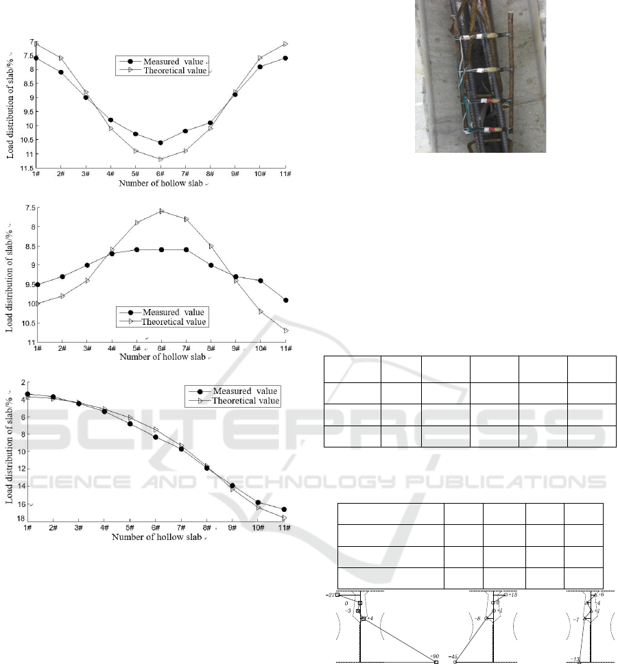
a) Condition 1
b) Condition 2
c) Condition 3
Figure 4 cross-section of the mid-section load transverse
distribution
It can be seen from Fig. 4 that there is not much
difference between the curve of measured values and
that of the calculated values from the hinge plate
method, but the measured transverse distribution
value is smaller than the calculated value and the
distribution curve is flat.
3.2 Strain increment of joints concrete
Horizontal strain gauges were embedded in No. 6
hinge at the cross-section, as shown in Figure 5. In
particular, it should be pointed out here that the
concrete joints between the bridge hollow slabs are
constructed strictly following the construction
procedures and have good quality after quality
inspection.
Figure 5 site buried seam strain measurement point
Under different loading conditions, the measured
results for strain increment of joints concrete are
shown in Table 1 and Table 2, the values are the
strain of joints concrete under the vehicle load, "+"
is the pull, "-" is the pressure. Figure 6 shows the
stress values at different heights of No. 6 hinge
joints.
Table 1 cross-section of the reaming measured value of
external strain/με
#2 hinge
joints
#5 hinge
joints
#6 hinge
joints
#7 hinge
joints
# 6 slab
Condition 1 - 72 90 58 5
Condition 2 -3 -48 -45 -17 -4
Condition 3 -8 -8 -13 -12 -3
Table 2 No. 6 hinge joints measured strain/με
NO.1 NO.2 NO.3 NO.4
Condition 1
-27 0 -3 4
Condition 2
15 0 1 -8
Condition 3
6 -4 1 -7
a) Condition 1 b) Condition 2 c) Condition 3
Figure 6 Distribution of strain at No. 6 hinge joint under
each working condition (Unit: με)
It can be seen from Figure 6, Table 1 and Table 2
that the normal strain exists in the transverse
direction of the concrete joint under three test
conditions, and the strain distribution is uneven
along the height of the joint, and the tensile and
compressive strain coexist. Under the condition 1,
the loading vehicle is arranged at the center position
of the bridge width. The upper part of the concrete
ICECTT 2018 - 3rd International Conference on Electromechanical Control Technology and Transportation
286

joint section is the compressive strain while the
lower part is the tensile strain. This proves that there
is a transverse bending moment acting on the
concrete joint caused by the vehicle load (The
bending moment at the lower edge is positive,
otherwise negative). On the contrary, under the
condition 2 and 3, the loading vehicles are arranged
outside of the bridge shoulder. The upper part of the
concrete joint section is tensile strain while the
lower part of the section is the compressive strain.
This proves that a transverse negative moment
actually acts on the concrete hinge joint caused by
vehicle load exists.
Under the condition 1 with loading at the center
position of the bridge width, the lower edge of each
hinge joint bear tensile stress, in particular, No. 6
joint at the center of the bridge width has maximal
tensile strain, 90 με, and the corresponding tensile
stress is 3 MPa calculated using C40 concrete, which
is enough to make the whole pouring concrete crack,
especially the concrete joints are at the bonding
between new and old concrete. As the tensile
strength of the bonding interface is far lower than
the concrete matrix, the joints bonding surface may
have been cracked.
4 CONCLUSIONS
In this paper, the field bridge load test was carried
out on the prefabricated hollow girder bridge. The
experimental results show that the hollow slab joints
are actually in the complex state of bearing bending
and shearing together, and the shear and transverse
bending moment of different joints change with the
action position of the vehicle load. In particular, the
horizontal middle hollow slab hinge joints bear
transverse positive bending moment under the
condition 1, while bear negative bending moment
when under the condition 2 and 3. The absolute
value of the edge stress is the largest irrespective of
the conditions.
ACKNOWLEDGEMENTS
The authors would like to acknowledge the financial
support provided by Transportation Science and
Technology Project of Jiangxi Provincial [Grant
2014C0001].
REFERENCES
Shao Xudong, Li Lifeng. Bridge Design and Calculation
[M]. Beijing: China Communications Press, 2007.
Guohao Li. Calculation of Lateral Distribution of
Highway Bridge Load [M]. Beijing: China
Communications Press, 2007.
Liu Chenguang. Research on design method of transverse
joint for precast hollow concrete slab bridge [D].
Ha’erbin: Harbin industrial university, 2002.
Pu Guangning, Rao Zhong, Meng Tunliang, Ding
Xueliang. Cause analysis and countermeasures for
diseases of 30 m prestressed concrete hollow slab [J].
Highway, 2008, 7: 175-179.
Study on mechanism and reinforcement processing of
“single slab bearing” disease of hollow core slab beam
bridge [J]. Journal Huazhong University of Science
and Technology (Natural Science Edition), 2008,
36(2): 118-121.of
Study on the Stress State of Hollow Slab Hinged Joint Under Vehicle Load
287
