
Missing Rail Fastener Detection Based on Machine Vision Method
Yongzhi
Min
1*
,
Benyu Xiao
1
, Hongfeng Ma
2
and Biao Yue
1
1
School of Automation and Electrical Engineering, Lanzhou Jiaotong University, Lanzhou, China
2
School of Electronical Information Engineering, Lanzhou Institute of Technology, Lanzhou, China
su_ymin01@qq.com, 13893178455@163.com, 13609345559@139.com, 1440127943@qq.com
Keywords: Fastener missing detection, area positioning, template matching, occlusion removal, machine vision,
minimum distance classifier.
Abstract: Rail fastener missing detection is an important part of railway daily inspection, according to the need of
modern railway automatic detection, a method of rail fastener missing detection based on template matching
is proposed in this paper. Firstly, in order to deal with the interference of environmental light, according to
the basic principle of machine vision, a simple rail inspection car is designed for image acquisition. Secondly,
according to the characteristics of the track image, the rail fastener area is located by using the mutation
information of the image. Then, through the establishment of template, test images are matched with the
template image, when the matching degree between test images and template images is low, it is need to detect
the occlusion area of the test image and if there is a occlusion in the test image, remove the occlusion area
from the test image and sample images to obtain new sample images and test image. Finally, the minimum
distance classifier is used to detect the missing rail fastener. Simulation results show that the correct detection
rate of this algorithm is 93.7% and the average detection time of each image is 385.74 ms, providing a
reference for real-time detection of railway line.
1 INTRODUCTION
With the rapid development of high-speed railway,
how to ensure the safe operation of the train has
attracted more and more attention of the public. Track
fastener is an important component for connecting
rail and track sleeper, playing an important role of
holding on the track gauge and preventing the rail
from vertically and horizontally moving relative to
the track sleeper, once be lost will bring security risks
to the safe operation of the train(Gibert, et al, 2017).
In recent years, many domestic and foreign
scholars have done a lot of research on the detection
of missing track fastener and have obtained some
achievements. Among them, Wang L et al.(2011) use
principal component analysis (PCA) algorithm to
extract the feature vector of the rail fastener nut and
use the minimum distance classifier to detect the
fastener. Yang J et al. (2011) use the orientation field
algorithm and the template matching method to detect
the state of the rail fastener. Jia L H(2014) carries on
processing to the image edge by using mathematical
morphology, intercepts the sub module from the test
images to match with the standard rail fastener image
and uses the support vector machine (SVM) method
to detect the missing fastener. Yan F(2014) extracts
the edge feature of the fastener image, and then
respectively use the BP neural network and fuzzy C
mean clustering method to identify the missing
fastener.
The existing researches mainly focuses on the
case that the track fastener image is not be occluded.
In that case, the local characteristics of rail fastener is
not interfered by the external environment and can be
easily extracted. However, the track fasteners may be
obscured by such as fallen leaves or food bags et al.
in the actual railway lines, causing some of local
features of track fastener be split and cannot be
accurately extracted.
Taking into account the situation that rail fastener
may be obscured by some occlusions, a method based
on machine vision method for the detection of
missing rail fastener is proposed in this paper. Firstly,
the rail fastener area is located by using the position
relationship among components of the track image.
Then, select a track image that contains rail fastener
a track image lacking of track fastener as the sample
images, and the test image is compared with the
sample images. When there is a high matching degree
between the test image and the sample images, the
Min, Y., Xiao, B., Ma, H. and Yue, B.
Missing Rail Fastener Detection Based on Machine Vision Method.
In 3rd International Conference on Electromechanical Control Technology and Transportation (ICECTT 2018), pages 119-124
ISBN: 978-989-758-312-4
Copyright © 2018 by SCITEPRESS – Science and Technology Publications, Lda. All rights reserved
119
result can be obtained directly, while the difference
between test images and sample images is large, it’s
needed to consider the influence of the may existing
occlusion on the matching result, therefore, it is
necessary to firstly detect the occlusion of the test
image, if there is a occlusion in the test image,
removing the occlusion area to obtain new samples
and test image to minimize the impact of the
occlusion on the detection results. Using the
minimum distance classifier to get the final detection
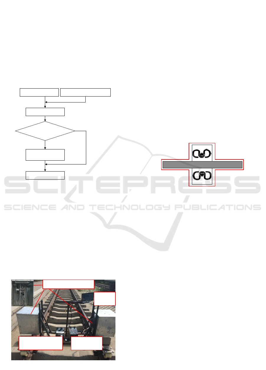
result. The detection flow of the algorithm is shown
in figure 1.
Fastener area positioning
Matching degree between
sample and test image is high?
Detection and removal of
occlusion area
Sample images
Final test result
N
Y
Test images
Figure 1: Schematic diagram of algorithm detection
process.
2 IMAGE ACQUISITION
If track images are collected directly in natural
environment, they may be affected by natural light,
making the illumination of images is inconsistent and
the algorithm will be difficult to carry out a unified
process to images (Li, et al, 2010). In order to avoid
the influence of the external light, a rail fastener
detection system is designed and is shown in figure 2.
Figure 2: Rail fastener missing detection system.
A CCD camera is used to meet the requirement of
the system on the acquisition speed and an 8mm lens
is installed to coordinate with the camera. An
industrial control computer and a display screen are
equipped in the rail inspection car to display and
process the images.
3 AREA POSITIONING
The relationship between the track fastener, rail and
track sleeper in a track image is that the track sleeper
and rail intersect vertically, the track fastener is
located on the track sleeper and distributed on two
sides of the rail(Liu J J, et al,2015). The positional
relation of a track image is shown in figure 3.
Therefore, according to the position relation in the
track image, the rail and the sleeper area can be
located firstly, and then the fastener region will be
positioned.
Figure 3: Sketch map of track area structure.
In a track image, there are a lot of edges in the
stone ballast area for a large number of stone ballast
exist in this area, while the rail and track sleeper area
are smoother and have only a small number of edges.
Defined the marker number of gray mutation between
adjacent pixels is as
q
n
:
1, *| ( , ) ( , 1) | | ( , ) ( 1, )|
0, *| ( , ) ( , 1) | | ( , ) ( 1, )|
q
h f i j f i j v f i j f i j T
n
h f i j f i j v f i j f i j T
ì
- + + - + >
ï
ï
=
í
ï
- + + - + <
ï
î
(1)
The gray value of (i, j) is
( , )f i j
and T is a
threshold. In this paper, we set the value of T as 2/3
of the average gray value of image, when we
calculate the gray mutation in the horizontal direction,
take h=0, v=1, while calculate the gray mutation in
the vertical direction, take h=1, v=0.
The statistical value of the gray mutation of k-th
row and k-th column can respectively be obtained by
formula (2) or formula (3):
,
1
=,
J
Hi i j
j
N n i k
=
=
å
(2)
,
1
=,
I
Vj i j
i
N n j k
=
=
å
(3)
I is the row number of image while J is the column
number. k represents the k-th row or the k-th column.
Image acquisition section
Display
screen
Power
Supply
Industry personal
computer
ICECTT 2018 - 3rd International Conference on Electromechanical Control Technology and Transportation
120
The number of gray change points in horizontal
and vertical directions of the image respectively is:
H
1
I
Hi
i
NN
=
=
å
(4)
V
1
J
Vj
j
NN
=
=
å
(5)
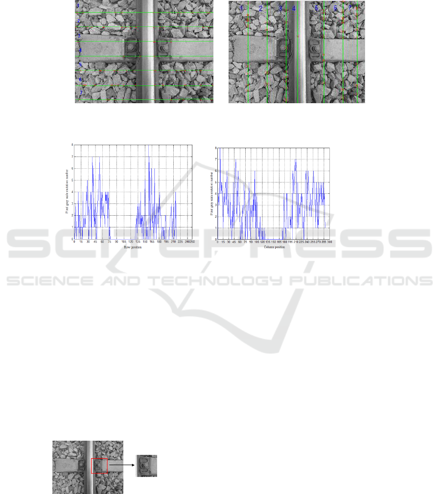
According to the formula (1)-(5), the gray change
point mark map and the statistical graph are
respectively shown in figure 4 and figure 5.
(a) Horizontal direction (b) vertical direction
Figure 4: Gray change point mark map.
(a) Horizontal direction (b) vertical direction
Figure 5: Statistical graph of image gray mutation.
From figure 4 we can see, the number of gray
change points in the straight line that through the
stone ballast area is more than that in the through
the track sleeper area or rail area straight lines.
Because there are fewer gray abrupt points in the
areas of track sleeper or rail, the bottom is formed in
the statistical chart as shown in figure 5.
The location to the track sleeper area and rail area
can be completed by searching the bottom position in
figure 5, and then the fastener region is positioned by
the position relation in a track image expressed in
figure 3. The coarse positioning diagram of rail
fastener image is shown in figure 6.
Figure 6: Fastener region location and segmentation.
4 DELETION DETECTION
4.1 Image registration
In order to get the difference image between test
images and sample images, it is necessary to register
test images and sample images firstly. Due to test
images may missing rail fastener as well as may be
blocked by occlusion, therefore, in this paper, the
edges of rail and track sleeper are selected as the
image registration features. Even in some occlusion
conditions that shown in figure 7, we can detect at
least one edge line (as shown in figure 8), which is
helpful for us to register the test images and sample
images. Select images shown in figure 9 as sample
images of this paper.
Missing Rail Fastener Detection Based on Machine Vision Method
121
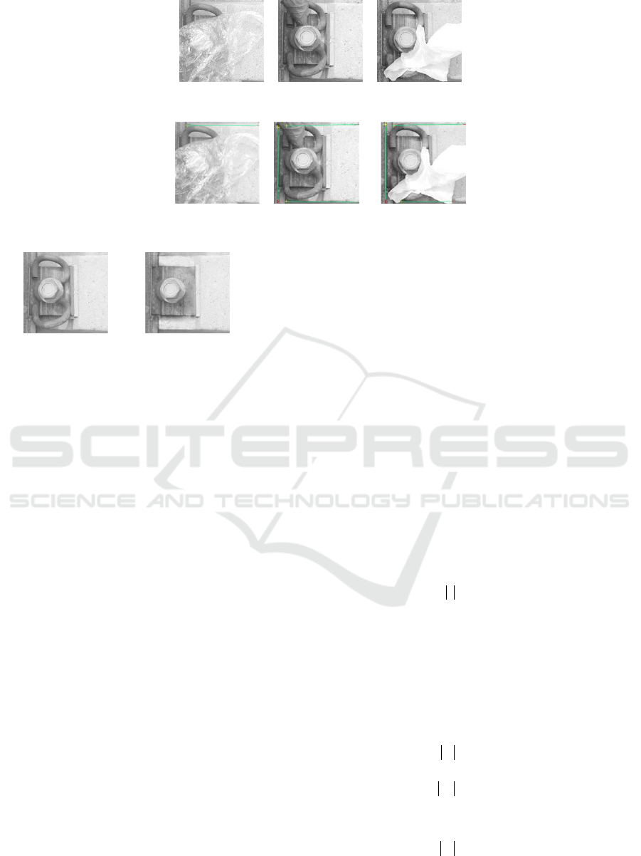
Figure 7: Some of occluded rail fastener images.
Figure 8: Line detection results.
(a) Containing fastener (b)Missing out fastener
Figure 9: Sample images.
4.2 Occluded area detection and
removal
The detection and removal of the occlusion areas is
an important part of the rail fastener detection. Once
the test image is an occluded image, the occlusion
will interfere with the extraction of the fastener
features. The key to the occluded image detection is
to find an effective method to reduce the influence of
occlusion area. This paper presents an improved rail
fastener detection method based on removing
occlusion area. The implementation of this method is
divided into two stages: in the first stage, judging and
detecting the occlusion area in the test image. In the
second stage, carrying out unified treatment on the
occlusion area in the test image and the region that
corresponding to the occlusion area in the sample
images. The specific steps are as follows: ①
According to the comparison result between the test
image and the sample images, get the difference
image between the test image and the corresponding
sample image. ② Compare the gray value of the
difference image with the threshold Y, when the pixel
gray value is larger than the threshold value Y, set the
value of these pixels to 255, otherwise set these pixels
gray value to 0, in this way, we get a new difference
image. ③ Get the removed occlusion images by
subtracting the difference image from the test image
and the sample images respectively.
5 MINIMUM DISTANCE
CLASSIFIER
Compared with the K nearest neighbor method and
the neural network method, the speed of the minimum
distance classifier is faster, therefore, minimum
distance classifier is often chosen for real-time on-
line inspection systems(Liu, 2009). The specific
process of using the minimum distance classifier to
complete the defect detection of rail fastener is as
follow.
Define the modulus of image I as:
11
= ( , )
nm
xy
I I x y
==
邋
(6)
Where n and m are image size of I,
( , )I x y
is the
gray value at (x, y).
Suppose that
F
I
represents sample image
contained with rail fastener and
M
I
represents
sample image of missing rail fastener. The modulus
of image
F
I
and
M
I
respectively are:
FF
11
= ( , )
nm
xy
I I x y
==
邋
(7)
MM
11
= ( , )
nm
xy
I I x y
==
邋
(8)
The modulus of the test image
T
I
is:
TT
11
= ( , )
nm
xy
I I x y
==
邋
(9)
ICECTT 2018 - 3rd International Conference on Electromechanical Control Technology and Transportation
122

Compare
T
I
with
F
I
and
M
I
to obtain the
final test results.
6 EXPERIMENTAL RESULTS
AND ANALYSIS
We collected 480 rail fastener images on the spot.
Among them, 467 rail fastener images contain
fastener, 13 images lack of the track fastener. Due to
the small number of the missing fastener images, we
added 20 missing fastener images by using artificial
synthesis method. In this way, the total number of
experimental images is 500. At the same time, in
order to increase the diversity of occluded images, we
randomly selected 20 images from existing images
and add occlusion into these images to obtain 20
occluded images (Cai, et al, 2010).
In order to verify the performance of the
algorithm in different cases, we carried out three
simulation experiments. In experiment 1, all the test
images are all non occluded track images, and this is
the most common experimental method used in
fastener detection algorithms. In order to compare
with experiment 1, in experiment 2, we used occluded
images as the test images. In Experiment 3, the test
image set contains both non occluded and occluded
images, and this is the most consistent with the actual
railway scene. The distribution of sample and test
images of the three experiments are respectively
shown in table 1, table 2 and table 3. It should be
noted that in order to reduce the influence of
occlusion on the test results, the occluded images are
not included in the sample images, the test images
and the sample images are randomly selected in
different experiments. The results of the three
experiments is shown in table 4.
Table 1: Distribution of sample and test images in experiment 1.
Category
Non occluded image
with fastener
Non occluded
image missing
fastener
Occluded image
with fastener
Occluded image
Missing fastener
Sample images
20
10
0
0
Test images
432
17
0
0
Table 2: Distribution of sample and test images in experiment 2.
Category
Non occluded image
with fastener
Non occluded
image missing
fastener
Occluded image
with fastener
Occluded image
Missing fastener
Sample images
20
10
0
0
Test images
0
0
15
6
Table 3: Distribution of sample and test images in experiment 3.
Category
Non occluded image
with fastener
Non occluded
image missing
fastener
Occluded image
with fastener
Occluded image
Missing fastener
Sample images
20
10
0
0
Test images
432
17
15
6
Table 4: Detection result.
Category
Experiment 1
Experiment 2
Experiment 3
Correct detection rate
94.6%
87.5%
93.7%
Per frame Image detection time
367.21 ms
425.58 ms
385.74 ms
Missing Rail Fastener Detection Based on Machine Vision Method
123

It can be seen from the experimental data of table
4 that the detection of occluded images takes a longer
time than that of non occluded images, this is because
there is a process of removing occlusion when
processing occluded images. But in actual scenes, the
proportion of occluded images to the total image is
unlikely to be so high, so, the overall speed of this
algorithm is good, just like the result of experiment 3.
The experimental data also show that the correct
detection rate is less affected by occluded images.
7 CONCLUSION
In view of the possible occlusion problem in defect
detection of rail fastener, this paper propose a method
based on machine vision. The fastener area is
positioned firstly and the template images are
established. The test images are directly matched
with the sample image, accelerating the detection
speed of the algorithm. When the difference between
the test images and the template images is large, by
detecting the occlusion area in the test image and
removing the region corresponding to the occlusion
area from the sample images as well as the test image,
the influence of the occlusion area on the detection
can be effectively reduced and the accuracy of the
detection algorithm is improved. The algorithm
proposed in this paper has higher recognition rate and
strong robustness, it can be used for reference in the
detection of similar occlusions. But the sample image
and the test images used in this paper contains no
track images that acquired in the rain or under strong
sunlight condition, therefore, the sample set is still
failure to fully reflect the actual situation on the rail
line. So, the detection of missing track fasteners for
different weather will be the focus of the next study.
ACKNOWLEDGEMENTS
This research was supported by the National Natural
Science Foundation of China(Grant No.61663022
and No.61461023), the Open Project of Gansu
Province Plateau Traffic Information and Control
Engineering Laboratory(Grant No.20161105), the
Program for Changjiang Scholars and Innovative
Research Team in University(Grant No.IRT_16R36),
and the Postdoctoral Special Foundation of Lanzhou
Jiaotong University(Grant No.2017002).
REFERENCES
Cai C, Zhang M, Zhu J P. 2010. Classification and
identification of weed seeds based on compressed
sensing theory. Scientia Sinica (Informationis),
40(suppl):160.
Gibert X, Patel V M, Chellappa R. 2017. Deep Multitask
Learning for Railway Track Inspection. IEEE
Transactions on Intelligent Transportation Systems,
arXiv:1509.05267(99):1-12.
Jia L H. 2014. Research of the detection algorithm and
design the system on high speed railway fastener based
on DSP. University of Electronic Science and
Technology of China.
Li G, He Y Y. 2010. A new method for pavement crack
detection and classification based on non-uniform
illumination. Acta Photonica Sinica, 39(8):1405-1408.
Liu J J, Li B L, Luo J Q, et al. 2015. Railway Fastener
Detection Algorithm Integrating PHOG and MSLBP
Features. journal of southwest jiaotong university,
50(2):256-263.
Liu X S. 2011. Face recognition based on PCA and SVM
algorithm. Computer & Digital Engineering,
39(7):124-126.
Wang L, Zhang B, Chen X A. 2011. Inspection system for
loss of rail fastening nut based on computer vision.
Computer Engineering and Design, 32(12): 4147-4150.
Yang F. 2014. Research on image detection system of metro
rail missing fasteners. Southwest jiaotong University.
Yang J, Tao W, Liu M, et al. 2011. An Efficient Direction
Field-Based Method for the Detection of Fasteners on
High-Speed Railways. Sensors, 11(11):7364-7381.
ICECTT 2018 - 3rd International Conference on Electromechanical Control Technology and Transportation
124
