
Research on the Environmental Control System of the Equipment
Bay for A High Altitude Long Endurance Solar-powered UAV
Fangyong Li, Han Yang, Xingjuan Zhang* and Chunxin Yang
School of Aeronautic Science and Engineering, Beihang University, Beijing 100191, PR China
{Coresponding author:zhangxingjuan@buaa.edu.cn}
Keywords: Long endurance, Solar-powered, Unmanned aerial vehicle, Environmental control system.
Abstract: Substantial efforts have been focused on developing high altitude long endurance solar-powered unmanned
aerial vehicles (LESP UAVs). With increasingly integrated and compact electronic equipment, the demand
for effective heat dissipation becomes more critical but challenging. Aiming at LESP UAV’s equipment bay
with the cooling capacity demand of 5kW, after the availability of heat sink is analysed, a single-stage and
two-stage vapor compression refrigeration cycle based on radiation cooling are proposed. By using
thermodynamic analysis and quality estimation, the corresponding quantitative relationship is obtained, and
the variation between cooling capacity and power consumption/system weight are calculated. Combined
with the engineering application, the suitable conditions of two schemes are given. The results can provide
theoretical and engineering guidance for the research in this field, and have good engineering application
value.
1 INTRODUCTION
Solar-powered UAV is an unmanned aerial vehicle
that uses solar radiation as a power to fly at high
altitude for more than a few weeks. Because of the
broad application prospects of solar aircraft, many
countries and organizations are competing in the
research of solar aircraft, and various models emerge
in endlessly. Such as NASA’s Helios protype,
HELIPLAT in Italy; and the Rainbow in China, etc.
(Gao, et al., 1995; Jiang, 2017; Gao and Zhu, 2016;
Zhang J and Zhang DH, 2016).
However, the development of solar UAVs is still
facing many key technical issues that need to be
addressed urgently. For example, the heat
dissipation of equipment bay for the solar-powered
unmanned aerial vehicle (UAV) directly affects the
reliability of the UAV, which has been the focus of
the research. To the authors’ best knowledge, no
relevant work has been published in open literature.
In this paper, two vapor cycle refrigeration schemes
are proposed to solve the heating demand for LESP
UAV’s equipment bay.
2 DESIGN REQUIREMENT
The flight altitude of the LESP UAV is in the range
of 16~20km (day cruise at 20km with the cruise
speed of 34m/s, night cruise at 17km with the cruise
speed of 27m/s). The layout of the LESP UAV
equipment modules is shown in Figure 1, and they
are in symmetrical distribution arrangement, and
each set of heat dissipating power is 2.5kW. The
temperature control target of its equipment bay is no
less than 40℃.
Equipment bays
Figure 1: Layout of equipment bays.
Li, F., Yang, H., Zhang, X. and Yang, C.
Research on the Environmental Control System of the Equipment Bay for A High Altitude Long Endurance Solar-powered UAV.
In 3rd International Conference on Electromechanical Control Technology and Transportation (ICECTT 2018), pages 87-91
ISBN: 978-989-758-312-4
Copyright © 2018 by SCITEPRESS – Science and Technology Publications, Lda. All rights reserved
87
3 HEAT SINK ANALYSIS
The first problem in the design of the cooling system
is to find a suitable heat sink. Due to the high
altitude of the LESP UAV with low atmosphere
pressure and therefore low air density, the
convective heat transfer is limited, and the radiation
heat transfer becomes more dominant.
The calculation formula of the convective
radiation intensity is
0
()
a a w
Q h T T
(1)
Wherein, T
w
and T
0
indicate the temperature of
the radiant surface and the ambient temperature,
respectively, K;
The calculation formula of convective heat
transfer coefficient is (Ma, et al., 2010)
1/3
0
0
0
0.664
ar
v
hP
L
(2)
Wherein, λ
0
is the thermal conductivity of the
corresponding atmosphere, W/(m·K); v
0
is the air
flow velocity, m/s; γ
0
is the kinematic viscosity, m
2
/s;
L is the characteristic length of the heat dissipating
surface, m.
The calculation formula of radiation intensity is
44
()
r w a
Q T T
(3)
Wherein, ε is the emissivity; σ is the Stephen
Boltzmann constant; T
a
is the ambient temperature,
K.
Take the chord length of 2m as the feature size,
the convection heat transfer coefficient at 20km with
cruise speed of 34m/s can be calculated about
4W/(m
2
·K) by using Eq.2, herein, the ambient
temperature is set to 290K.
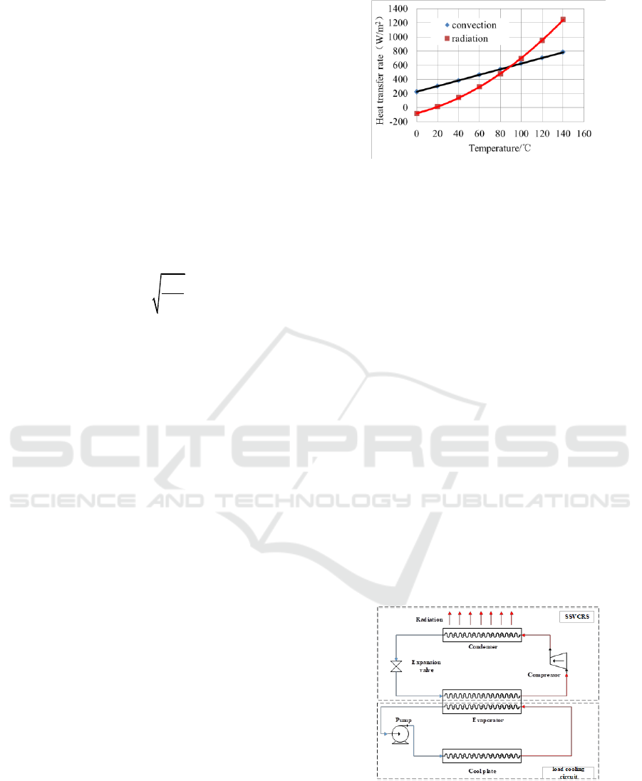
The results of the calculation are shown in Figure
2. The radiation heat transfer is much higher than the
convective heat transfer in the high temperature zone.
Due to limited research on convective heat transfer
in the high altitudes, the uncertainty of calculated
convection heat transfer coefficient could be very
high. Therefore, for conservative design, the heat
sink in this paper is based on the worst condition in
which only radiation heat transfer is considered. In
practical application, the target heat transfer
performance can be achieved with additional
convective heat transfer component.
Figure 2: Comparison of heat transfer rate between
convection and radiation heat transfer.
4 SYSTEM DECRIPTION
Two vapor cycle refrigeration systems are proposed.
Considering the centre of gravity of the system, the
scheme below shows only a set of system
schematics based on the symmetry of the equipment
bay.
4.1 STVCRS
The schematic diagram and thermodynamic process
diagram of a single stage vapor cycle refrigeration
system (STVCRS) are shown in Figure 3. The
system is composed of load cooling circuit and
refrigeration cycle, and load cooling circuit will
remove heat dissipated by the equipment bay.
Taking into account the low temperature condition at
high altitude, the cooling liquid used in this system
is ethylene glycol solution with mass fraction of
66%, and R134a as the refrigerant of vapor cycle
refrigeration system (VCRS).
ICECTT 2018 - 3rd International Conference on Electromechanical Control Technology and Transportation
88
50 100 150 200 250 300 350
500
1000
2000
5000
10000
h [kJ/kg]
P
[
k
P
a
]
1
2
3
4
Figure 3: Single stage steam cycle cooling scheme and
thermodynamic process diagram.
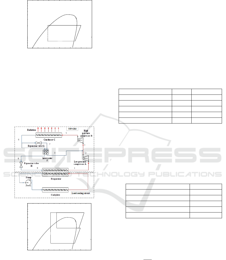
4.2 TSVCRS
At a higher wall temperature of condenser, heat
transfer area and component mass become smaller.
Therefore, a two stage vapor cycle refrigeration
system (TSVCRS) is proposed to improve the
condensing temperature (Fig.4).
50 100 150 200 250 300 350
5
x
10
2
10
3
2
x
10
3
5
x
10
3
10
4
h [kJ/kg]
P
[
k
P
a
]
1
2
3
4
5
68
7
9
Figure 4: Schematic diagram and thermodynamic process
of TSVCRS.
5 PERFORMANCE ANALYSIS
In order to explore the feasibility of the above-
mentioned systems in the application of LESP UAV,
the refrigeration system power consumption and
system weight estimation are analysed.
5.1 Thermodynamic Calculation
Theoretical thermodynamic models for the above-
mentioned two systems are referred to reference
(Wu, 2007), and their performance results are shown
in Table 2.
Table 2: Performance results of two systems.
SSVCRS
TSVCRS
Evaporate temperature,℃
30
30
Condensing temperature,℃
68.7
90
Sub-cooling temperature,℃
5
5
Sub-heating temperature,℃
5
5
COP
4.63
1.88
5.2 Mass Estimation
(1) Evaporator
The evaporator employs the compact heat
exchanger for aircrafts. Table 1 gives the
relationship between the cooling capacity and the
corresponding quality.
Table 1: Plate type for heat exchanger selection.
Heat exchange capacity / kW
Mass / kg
2.0
0.68
2.5
0.8
3.0
0.96
4.0
1.16
5.0
1.36
(2) Compressor
According to the light weight requirement of the
airborne refrigeration compressor and our previous
research work, the ratio of the total weight M
rc
to the
cooling capacity Q of the centrifugal refrigeration
compressor can be estimated as
r
1.85 ~ 2 kg/kW
c
M
Q
(4)
(3) Condenser
The selected condenser diagram is shown in
Figure 5. Condenser pipe is
81
mm. The
refrigerant flows in the tube, and the radiation plate
is welded outside the tube.
Research on the Environmental Control System of the Equipment Bay for A High Altitude Long Endurance Solar-powered UAV
89
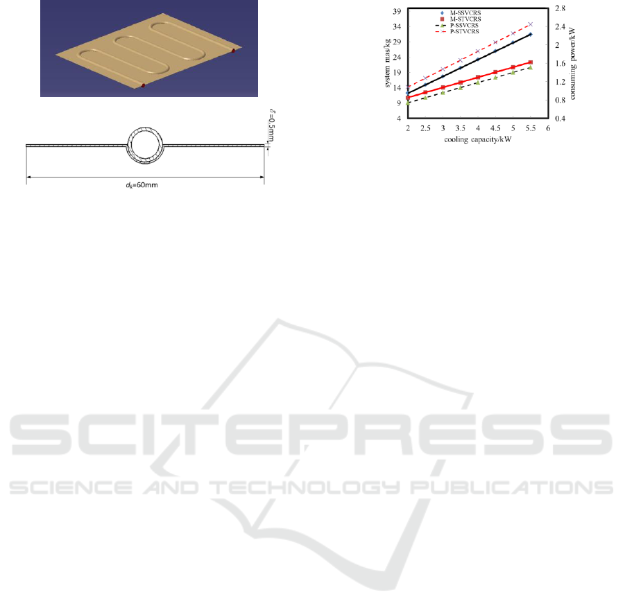
Figure 5: Schematic of radiation condensers.
The estimated correlations of the condenser mass
with the cooling capacity of a SSVCRS and
TSVCRS are shown below respectively:
5.2
Con SS
MQ
(5)
2.9
Con TS
MQ
(6)
(4) Expansion valve
The thermal expansion valve is selected by the
Danfoss TCEL3.5 type thermal expansion valve
(suitable for the range of refrigeration is not more
than 12kW), its weight is about
0.37kg
rv
M
(7)
0.37kg
rv
M
(8)
(5) Refrigerant charge
The Enviros Consulting Ltd. "Refrigerant Charge
Calculator" software is used to make a simple
estimate of the weight and charging amount of the
heat exchanger. There is no high or low pressure
storage tank in the estimation. At the same time, the
lubricating oil is not considered because of the oil-
free centrifugal refrigerating compressor used in this
work.
(6) Load cooling circuit
According to the market research, the ratio of the
cold plate mass to the heat dissipation area is
approximately equal to 8kg/m
2
. The length of the
connecting pipe can be estimated approximately
according to the length of the fuselage, and the pipe
can choose the specifications of the aluminium tube
of
81
with a mass density of 0.06kg/m.
The mass estimation method of the pump is
according to Eq.4. In addition, the power
consumption of the pump is less than 0.3kW within
the operating range.
Therefore, the relationship between the cooling
capacities with consuming power/mass of the two
systems is given respectively in Figure 6. From the
aspect of mass assessment, TSVCRS has substantial
advantage but high power consumption is not
favoured.
Figure 6: System mass varies with cooling capacity
6 CONCLUSION
This paper proposed two cooling systems of
equipment bay for the long endurance solar-powered
UAV, and conclusion based on systematic analysis
can be summarized as follows:
(1) For the heat sink of the long endurance solar-
powered UAVs in the near space, the conservative
design and system reliability requires only
considering heat transfer based on radiation without
convective component.
(2) As far as system energy consumption
concerns, it is suggested to adopt single stage vapor
cycle system. While, from the perspective of mass
concern, it is suggested to adopt two-stage vapor
cycle system; however, the system is more complex.
(3) Limited by the high altitude thermal
environment for condenser radiation, the condenser
contributes to overall system weight in a larger
portion. By increasing the condensing temperature,
the heat transfer capability and the mass of the
radiation condenser can be reduced. The condenser
design and weight can be optimized in future’s work.
ACKNOWLEDGEMENTS
The research presented in this paper was supported
financially by the National Basic Research Program
of China (the 973 Program) through Grant No.
2012CB720100.
REFERENCES
Gao GL, Song BF, Li ZK and Ding X, 2010. Key
technologies of solar powered unmanned air vehicle.
Flight Dynamics. 28 (1), p1-4. (in Chinese)
ICECTT 2018 - 3rd International Conference on Electromechanical Control Technology and Transportation
90

Jiang JK, 2017. Successful flight of a new rainbow solar
UAVs. the third edition of the People's Daily
Overseas Edition, June 14th. (in Chinese)
Gao F and Zhu DR, 2016. Design and optimization of
solar unmanned aerial vehicle heat management
system. Refrigeration and air conditioning. 16 (11),
p32-37. (in Chinese)
Zhang J and Zhang DH, 2016. Analysis on the main
design points of high altitude long endurance solar
UAVs. Acta aeronautical journal. 37 (S1), pS1-S7. (in
Chinese)
Ma W, Xuan YM and Han YG, 2010. Analysis on thermal
environment in near space and thermal design method
for ow-speed aircraft. Journal of astronautics. 31 (5),
p1272-1277. (in Chinese)
Yang SM, 2006. Heat transfer. Beijing: Higher education
press. (in Chinese)
Wu YZ, 2007. Refrigeration principle and equipment. 3rd
ed. Xi'an: Xi'an Jiaotong University press. (in
Chinese)
Shou RZ and He HS, 2004. Environmental control
technologies for aircrafts. Beijing: Beihang University
press. (in Chinese)
Morris T., Godecker W., Crowe L. and Metzler M., 1982.
Environmental Control of an Aircraft Pod Mounted
Electronics System. SAE Technical Paper 820869.
Godecker W. J., Lentz J. C., Parme C. B., Wigmore D. B.
and Winans K. B., 1992. Vapor Cycle System for a
Fighter Aircraft - The Lantirn ECU Lessons Learned.
SAE Technical Paper 921184.
Research on the Environmental Control System of the Equipment Bay for A High Altitude Long Endurance Solar-powered UAV
91
