
From a BPMN Model to an Aligned UML Analysis Model
Wiem Khlif
1
, Nouchène Elleuch Ben Ayed
2
and Hanêne Ben-Abdallah
3
1
University of Sfax, Mir@cl Laboratory, Sfax, Tunisia
2
Higher Colleges of Technology, Abu Dhabi, U.A.E.
3
King Abdulaziz University, Jeddah, K.S.A.
Keywords: BPMN Model, Use Case Diagram, System Sequence Diagrams, Class Diagram, MDA, CIM-to-PIM
Transformation, Business Context.
Abstract: Aligning the information system (IS) of an enterprise to its corresponding Business Process (BP) model is
crucial to the consistent analysis of the business performance. However, establishing or maintaining this BP-
IS alignment is not trivial when the enterprise develops a new IS or changes its IS or BP. The difficulty mainly
stems from the differences in the knowledge of the information system developers and the business process
experts. This paper proposes a new requirements engineering method that helps software analysts to build an
IS analysis model, which is aligned to a given BP model. The built model can be used to develop a new IS
and/or to examine the deviation of the new IS from the existing one after BP/IS evolution. The proposed
method adopts an MDA approach where, at the CIM level, the BP is modelled through the standard BPMN
and, at the PIM level, the aligned IS model is generated as UML use case diagram documented with a set of
system sequence diagrams and the corresponding class diagram. Its originality resides in the CIM to PIM
transformations which account for the BP structural and semantic perspectives to generate an aligned IS
model.
1 INTRODUCTION
Business Process Models (BPM) are usually used to
define the organization’s goals, strategies, tasks, and
business rules. In the development of an Information
System (IS), the enterprise’s BPM must be deeply
analyzed to gather and identify the IS requirements
that approprietly fit the enterprise business process.
In other words, the BPM can be seen as the backbone
of IS requirements engineering. Indeed, a perfect
alignment between the IS and BP models maximises
return on investment and it is key to the success of an
enterprise (Aversano et al., 2016).
Several approaches have addressed the generation
of IS Functional User Requirements (FUR),
represented by UML use case diagrams, from the
business specification. They differ in the use case
diagram elements they derive: the use cases and their
related actors, e.g. Rhazali et al. (Rhazali et al., 2016);
use cases and their textual documentation, e.g. Silva
(Siqueira and Silva, 2014); the relationships between
use cases, e.g. Berrocal et al. (Berrocal et al., 2014).
However, none of these approaches derives a use case
diagram that is documented with system sequence
diagrams—a common way to detail the abstract FUR
modeled by the use cases. In addition, they differ in
the degree of automation of the proposed approach.
Furthermore, a few works have looked into the
assessment (i.e., quality, precision, coverage) of the
generated diagrams, e.g., (Abrahão et al., 2013) and
(Vachharajani et al., 2016).
In (Khlif et al., 2018), we have presented an
MDA-compliant approach (OMG, 2006), called
DESTINY (a moDel-driven process aware
requiremenTs engineerINg methodologY). The main
aim of DESTINY is to automate the generation of an
IS Analysis represented through a UML class
diagram (a PIM of the IS system) from a BP model
described in the standard BPMN notation (ISO/IEC
19510, 2013) (a CIM of the IS system). The
generation is defined as transformations that ensure
the alignment of the class diagram with the BPMN
model by both accounting for the semantics and
structure of the BPMN model. Overall, compared to
existing works, our approach contributes to the BP-IS
alignment and IS analysis domain by proposing
semantic and structural transformation rules that aim
to obtain the class diagram. Existing works, does not
Khlif, W., Ayed, N. and Ben-Abdallah, H.
From a BPMN Model to an Aligned UML Analysis Model.
DOI: 10.5220/0006866606230631
In Proceedings of the 13th International Conference on Software Technologies (ICSOFT 2018), pages 623-631
ISBN: 978-989-758-320-9
Copyright © 2018 by SCITEPRESS – Science and Technology Publications, Lda. All rights reserved
623

handle the semantic constraints between classes.
These constraints specify the role or scope of a
modeling element to extend or clarify its semantics
and to limit the number of targeted instances.
In this paper, we tackle these limits by enhancing
the DESTINY arpproach (Khlif et al., 2018) with: 1)
a way to annotate a BPMN model by using the
business context as a means to encapsulate semantic
information pertinent to the business logic and
organizational aspect; 2) BPMN transformation rules
for identifying the use cases, their relationships, their
corresponding system sequence diagrams, and the
class diagram.
The remainder of the paper is organized as follows:
Section 2 overviews the DESTINY approach,
introduces the business context and discusses the
transformation definition strategy. Section 3 presents
the transformation rules which generate a use case,
system sequence model and a class model from a
BPMN annotated with its business context. Section 4
relates our work to existing BP-IS alignment works.
Finally, Section 5 summarizes the research results
and draws the future works.
2 OVERVIEW OF DESTINY
DESTINY (a moDel-driven procESs-aware
requiremenTs engineerINg methodologY) is an
MDA-compliant method that derives the IS
functional requirements from a given BP model. Its
novelty resides in the production of an IS analysis
model that is aligned to the input BPM. DESTINY
is based on a set of transformation rules to generate
use case diagram and the documentation of each use
case with a system sequence diagram that describes
its normal scenario. Furthermore, we propose a set of
transformation rule to generate the sequence and class
diagrams.
More specifically, we propose the concept of
business context as a means to define the IS scope by
delimiting the boundaries of the BPM. In addition, we
refine the use case size and scope by proposing a new
fragmentation method of the BPM. Finally, we define
new rules to generate coherent system sequence and
use case diagrams from the BP model. Furthermore,
we complement DESTINY by a set of transformation
rules to generate the class diagram.
Towards this end, we designed DESTINY
according to the MDA four-layer meta-modeling
architecture. The DESTINY method for CIM-to-PIM
transformation operates at the meta-model level. The
BPMN model constitutes the Computation
Independent Model (CIM) and the use case, system
sequence, and class diagrams represent the generated
Platform Independent Model (PIM).
Figure1: DESTINY conceptual process for BP-driven IS
FUR generation.
As illustrated in Figure 1, the DESTINY approach
operates in three phases:
1. The pre-processing phase during which the
Business Analyst first prepares the input BPMN
model to insure that it is well-structured and
well-defined. This requirement guides the
transformations and alleviates the complexity
of the identification of use cases, messages in
the sequence diagrams and methods in the class
diagram. To handle this requirement, on the
one hand, we rely on the BPMN syntactic meta-
modeling rules; on the other hand, we have
defined a set of linguistic syntactic patterns to
annotate the BPMN model as well as a business
context to enhance it with semantic information
related to the business logic and organizational
aspect (see Section 2.1). In addition, we use the
Jacobson stereotypes (Rumbaugh and
Jacobson, 2005) to tag the performers of the
BPMN model.
2. The transformation-definition phase during
which the Software Architect defines the CIM-
to-PIM transformations. DESTINY adopts two
types of transformations: pattern-based for the
CIM to the Use Case Diagram (UCD)
transformation, and 1-n mapping for the CIM
to the System Sequence Diagrams (SSD) and
class diagram transformation (see Section 2.2).
3. The transformation-implementation phase
during which the Software Engineer formalizes
/implements the transformation rules, which
provides for the automated generation of the
PIM model (a use case diagram, a set of system
sequence diagrams and a class diagram).
ICSOFT 2018 - 13th International Conference on Software Technologies
624

2.1 Linguistic Patterns and Business
Context
DESTINY offers a set of transformation rules from
an annotated BPMN model to generate an aligned
UML analysis model. It supposes that the BPMN
elements follow these linguistic syntax patterns:
1. BusinessObject+VerbalGroup+[Quantifier]
+BusinessObject to define the description
field of a BPMN element.
2. ActionVerb | CommunicationVerb +
BusinessObject | NominalGroup + [[to
ReceiverName] | [from SenderName]] to
label the BPMN tasks.
We mean by BusinessObject any entity that
describes the business logic. The NominalGroup is a
set of pre/post-modifiers, which are centered around
a HeadWord that constitutes the BusinessObject. The
pre-modifiers (respectively post-modifiers) can be a
noun, an adjective, or an ed/ing-participle
(respectively, a noun, an adjective, or adverb). The
VerbalGroup indicates the relationship type between
BusinessObjects. For example, the verbal group “is
entirely made of” or “is part of” expresses an
aggregation relationship between the business
objects. The Quantifier gives an idea of the
multiplicity. The expression between brackets is
optional.
Besides applying the linguistic patterns, the
software analyst prepares the BPMN model by
annotating it with its business context. The objective
is to complement the BPMN elements with semantic
information related to their functional and
organizational perspectives. The functional
perspective represents the process elements being
performed which are Activities (sub-processes, tasks).
The organizational perspective represents where and
by whom process elements are performed, which is
mainly reflected by the Pool and Lane concepts.
The business context of BPMN activities contains
the following information:
a. Actor ID is a unique identifier of the actor
responsible for performing the activity.
b. Actor Description indicates the relationships
between the activity and the involved actors.
c. Lane ID is the unique identifier of the lane,
which contains the activity.
d. Upstream and downstream ID is the unique
identifier of the activity on which this activity
directly depends.
e. Extended attributes describe the activity
properties. Each attribute can be a pure value
or a complex one representing a business
entity. This distinction is extracted from their
description.
f. Activity Description indicates the relationships
between the business entities and/or the
activity’s extended complex attributes. The
relationships’ semantic follows the first
linguistic pattern.
g. Resources are the data objects/stores that are
required by an activity. Each resource has a
name, extended attributes, and description,
which have the same semantic than the
activity’s extended attributes and description.
In addition, we augment the lane/Pool with the
following information to define its business context:
a. Lane/Pool ID is the unique identifier of the
lane/pool.
b. Lane Description (respectively Pool
Description) indicates the semantic relation
between the lane (respectively pool) and the
tasks/data object or stores (respectively the
lanes or tasks/data object or stores) that belong
to it.
c. Extended attributes describe the lane/pool
properties and have the same semantics defined
in section 2.1.e.
d. Actor_Description_Lane indicates its type that
can be either an entity or a performer. The
performer is classified into two categories: the
business worker who is internal to the
organization, and the business actor who is
external to the BP.
2.2 Transformation Definition Strategy
Once the BPMN model is prepared, the Software
Architect can start the definition of the CIM-to-PIM
transformations: The transformation from the CIM to
the Use Case Diagram (UCD) is pattern-based;
whereas the transformation from the CIM to the
System Sequence Diagrams (SSD) and Class
Diagram (CD) is a 1:n mapping. In fact, the 1:1
mapping between the CIM and use case meta-model
elements is not sufficient to preserve the semantics of
neither the business domain nor the modeling
languages. To overcome this deficiency, the software
architect should identify and enumerate a set of
patterns that respect the semantics of both the source
and target languages as well as the semantics of the
business domain. To do so, we defined BPMN model
fragments representing user-system interactions
based on the structural and semantic perspectives of
BPMN models. Recall that a use case represents a set
of actions that the system(s) should or can perform in
collaboration with one or more business workers or
From a BPMN Model to an Aligned UML Analysis Model
625

business actors, and it should provide some
observable result to them (Rumbaugh and Jacobson,
2005). A business worker represents an abstraction of
a human that acts within the business to realize a
service, while a business actor represents a role played
by some person or system external to the modeled
business and interacting with the business. As such, the
activities performed by the business actors are out of
the information system scope, and are ignored in the
identification of BPMN-to-UCD patterns.
We define a pattern as a fragment F in an
annotated BPMN process model P, that is a
connected, directed sub-graph of P starting at one
activity and ending at another activity such that F
contains the maximum number of activities between
either two gateways, a start node and a gateway, or a
gateway and an end node. A fragment F can be
decomposed into sub-fragments if it contains sub-
processes, which indicates the end of sub-fragment
and the beginning of another one.
Since each use case is obsolete without a textual
or graphical description, we associated with each
BPMN-to-UCD pattern a set of BPMN-to-SSD rules
to model the use case behavior, which is 1:n mapping
between the concepts of BPMN and sequence
diagram. To end this purpose, we lightly extended the
BPMN meta-model to handle the business context.
We added attributes and two new classes that are
Description and ExtendedAttributes. For each BPMN
element, we associate a Description that adds a
specific information to BPMN elements in terms of
the relationships between them. The Extended
Attributes class specifies the properties of each
BPMN element. The business context is also used to
generate the class diagram (Khlif et al., 2018).
3 FROM BPMN TO THE
ANALYSIS MODEL
The analysis model typically is composed of the Use
Case Diagram (UCD), a set of System Sequence
Diagrams (SSD), and the domain Class Diagram
(CD). Each SSD details/documents a use case by
describing the behavior through the actors involved in
the interaction, the system, and the operations.
The first step of IS FUR generation consists of the
definition of the IS scope. To do this, we assume that
the business analyst has respected the linguistic
syntactic patterns, defined the business context and
annotated each pool/lane, representing the
performers, by business actor or business worker tags.
All activities performed by a business actor are out of
scope. They will be ignored in the generation of the
use case diagram. However, some of them will be
used to derive the system sequence and class
diagrams.
The second step of IS FUR generation consists of
the elaboration of a set of transformation rules from
an annotated BPMN model to generate an aligned
UML analysis model. The BPMN-to-UCD
transformation rule operates on a canonical fragment
F obtained from the decomposition of the BPMN
model; While the BPMN-to-SSD and BPMN-to-CD
transformation rules act on each element of the
canonical fragment F.
R1. For each description field of a BPMN element,
extract the associations and multiplicities
between the generated classes according to the
semantics of VerbalGroup. If it is:
1. “is entirely made of” or “is part of” or any
synonyms, add an aggregation between the
business objects;
2. “is composed of” or any synonyms, add a
composition between the business objects;
3. “Is a/an”, add a generalization/specialization
between the business objects;
4. Else, add an association between the business
objects;
5. For all cases, except the generalization/
specialization, the quantifiers indicate the
multiplicity.
For example, “agent is an employee” is
transformed into a generalization/specialization
relation between the classes “agent” and “employee”.
This rule can be applied to the CD.
R2. For each extended attribute of the BPMN
element, add:
1. either an attribute to the class corresponding to
the BPMN element, if its extended attribute is
a noun that merely represents a pure value;
2. or a new class with the name extended
AttributeLabel, and an association between
the two generated classes by applying R1, if
the extended attribute is a complex noun.
Figure 2 illustrates the class diagram
corresponding to the annotated data object in terms of
extended attributes and description. The description
indicates a relationship between the Purchase order
data object and one of its extended attributes:
orderLine (Each Purchase order is composed of
order lines). The extended attributes of purchase
order data object are orderNumber, deliveryDate,
orderDate, and OrderLine. All of them are
transformed into class attributes, except the
orderLine, which is transformed into a class.
ICSOFT 2018 - 13th International Conference on Software Technologies
626
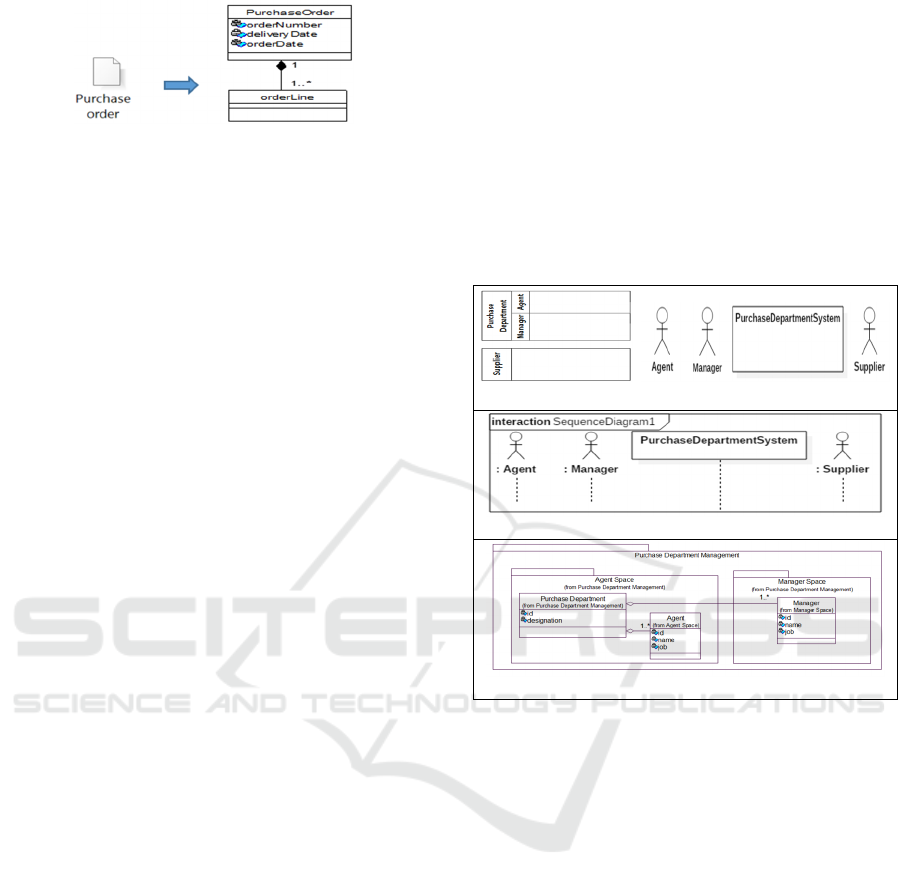
Figure 2: R2 illustration.
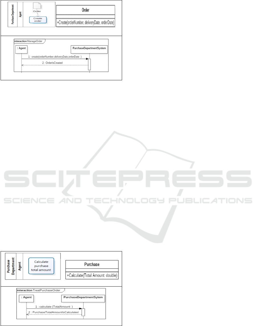
R3. For each Pool/lane:
1. UC and SSD:
a. For each lane whose label is a synonym to
"person", "agent", "System" transform it to
the corresponding actor that has the lane
name.
b. For each pool/lane whose label is a
metonymy of "department", "unit",
"division" or "management", transform it to
the actor where the name represents the
concatenation of the pool/lane name and the
word “Agent”.
2. CD:
a. Transform it to a package and class.
The package name depends on the
participant type which is a performer or an
entity. If the participant is a perfomer, then
the package name is a concatenation of the
lane name and the word “space” or “area”.
Else, the package name is a concatenation
of the lane name and the word
“management”.
The class name corresponds to the
pool/lane name. The class has as many
attributes to the extended attributes of the
corresponding pool/lane (See R2). The
class can have many associations
depending on the pool/lane description
(See R1).
b. For each lane, the package corresponding to
the pool includes the package corresponding
to the lane’s pool (See Figure 3).
R4. For each pool:
R4.1. If the pool includes only business workers,
then (See Figure 3):
a. UCD: transform the pool to a box that
determines the system perimeter. The system
name will be the concatenation of the pool
name and the word “System”. Then, add an
actor corresponding to each business
workers; apply Rule 3.1 to rename it.
b. SSD: add lifelines and activation zones
representing the system as well as all actors
which are generated by Rule 4.1.a.
R4.2. If the pool contains only business actors then
transform each business actor to:
a. UC: a secondary actor. Apply Rule 3.1.b to
rename the actor.
b. SSD: a lifeline and an activation zone for the
instance of the secondary actor generated by
Rule 4.2.a.
In both cases, transform the business actors and
workers of each pool to a package and class which are
generated by Rule 3.2. We note that the pool
containing only business actors is addressed in neither
UCD nor SSD. That has been tied to the fact that the
pool represents another business which is out of the
system scope.
BPMN model UCD
SSD
CD
Figure 3: R4 illustration.
R5. For each service task performed in the lane, we
apply R1 and R2. In addition, if the service task
label respects the renaming pattern:
R5.1. «Action verb + BusinessObject » then:
1. SSD:
a. add a new synchronous message from the
actor corresponding to the lane, which is
already generated by R4.2, to the system.
The message name is ActionVerb().
b. add a response message from the system
pointing back to the original lifeline. The
response label is a concatenation between
the BusinessObject and the passive voice of
the ActionVerb. Furthermore, the business
context of the activity or its associated data
object will indicate more details about the
method signature. In fact, we add all
extended
attributes as parameters of the
method ActionVerb() (See Figure 4).
2. CD: add a class with a name BusinessObject,
and a new method with a name ActionVerb()
(See Figure 4).
From a BPMN Model to an Aligned UML Analysis Model
627
BPMN model CD
SSD
Figure 4: Rule 5.1 illustration.
R5.2. «Action verb + NominalGroup», then
1. If the pre/post-modifier is a noun that merely
represents a pure value:
a. SSD: Apply Rule 5.1.1. on the HeadWord of
the NomnialGroup, and add parameters to the
identified method ActionVerb() as follows:
since the pre/post-modifier represents a pure
value, add it as a parameter (See Figure 5).
b. CD: Apply R5.1.2 on the Headword and add
an attribute to the class corresponding to the
HeadWord. The attribute has the same name
of pre/post-modifier. The attribute is also
considered as a parameter of the method
ActionVerb() (See Figure 5);
2. If the pre/post-modifier is a complex noun (an
entity) then:
a. SSD: Add the extended attributes of the
entity, as parameters of the method
ActionVerb() and apply Rule 5.1.1.
b. CD: Apply R5.1.2 on the Headword and add
a new class with the name pre/post-modifier,
and an association between the two generated
classes (HeadWord and pre/post-modifier).
BPMN model CD
SSD
Figure 5: R5.2 illustration (pure value).
R6. For each script/send/receive task, we apply R1
and R2. In addition, when the task name follows
this pattern:
R6.1. «CommunicationVerb+ BusinessObject + [[to
ReceiverName] | [from SenderName]] »:
1. SSD:
a. Add two lifelines representing respectively
an instance of the system, and the sender, if
they aren’t already created. If the receiver
noun is singular (respectively plural), also
add a lifeline representing an instance of the
receiver (respectively, a multi-instance of the
receiver).
b. If the task type is “send task” then, add a
asynchronous message between the instance
of Sender actor and the system as well as a
synchronous message from the system to an
instance (See Figure 6) or a multi-instance of
Receiver. The message is represented by the
CommunicationVerb() method which has
three arguments: “bo” instance of
BusinessObject, “r” (respectively, “r[]”)
instance of the receiver actor (respectively, an
array of instance of all receiver actors) and
“s” instance of the actor who sends “bo”.
Finally, add a response message from the
instance or multi-instance of Receiver to the
system called BusinessObjectIsReceived. We
recall that the information related to receiver
can be found either in the activity business
context or label.
c. If the task type is “receive task” then add an
asynchronous message called send() from the
sender to the system and a synchronous
message called send() from the system to the
instance of Receiver. The method has three
arguments: “bo” instance of BusinessObject,
“r” instance of the receiver actor, and “s”
instance of the sender actor. Add a response
message from the instance of Receiver to the
system called BusinessObjectIsReceived.
2. CD :
a. New Classes with name BusinessObject,
senderName and ReceiverName, if they were
not yet created;
b. New attribute email or phoneNumber in the
Class with a name SenderName and
ReceiverName;
c.
Method with a name CommunicationVerb()
to the class corresponding to the business
object.
In the case of Send Task, add three
parameters to CommunicationVerb()
method: “bo” instance of
BusinessObject and “r” instance of class
which receives “bo” and “s” instance of
class which sends “bo”.
ICSOFT 2018 - 13th International Conference on Software Technologies
628

In the case of receive Task, substitute
the CommunicationVerb() method with
a boolean method “isReceived()”.
In both cases, add a dependency
between the BusinessObject class and
Sender and Receiver classes, when there
is not an association between them.
BPMN model
SSD
CD
Figure 6: R6.1 illustration (case of send task, one receiver).
R6.2. « CommunicationVerb+ NominalGroup + [[to
ReceiverName] | [from SenderName]]»
1. If the pre/post-modifier is a noun that simply
represents a pure value
a. SSD: add parameters to the identified method
ComminucationVerb()
b. CD: apply R6.1.2 on the HeadWord and add
an attribute to the class corresponding to the
HeadWord. The attribute has the same name
of pre/post-modifier.
2. If the pre/post-modifier is a complex noun (an
entity) then:
a. SSD: Add the extended attributes of the entity
as parameters of the method
ComminucationVerb().
b. CD: apply R6.1.2 on the HeadWord, add a
new class with the name pre/post-modifier,
and an association between the two generated
classes (HeadWord and pre/post-modifier).
We note when this expression [[to ReceiverName]
| [from SenderName] ] is omitted, then we can extract
this semantic information from the description field
of the activity element according to R1.
R7. Transform to a class each data store/object,
identified by a name, if it is not already
generated. The class name has the same data
object name. Then, apply R1 and R2.
R8. For each gateway in the BPMN model P, add
1. SSD:
a.
An interaction operator Par with a combined
frame if the gateway is parallel. Each Par frame
has as many operands to the outgoing flows of
the parallel gateway.
b.
An Alt frame if the gateway is an exclusive or
inclusive one. Each Alt frame has as many
operands to the outgoing flows of the
exclusive/inclusive gateway. We note that
when an outgoing flow contains only an end
node, it will not be calculated. If the number of
operands is equal one, then change Alt frame to
Opt frame. In all cases, the outgoing message
label is used to define the guard of each
operand.
2. CD: If the exclusive gateway label refers to an
existing business object or a new one, then apply
the State design pattern on it with: the Context
class name corresponds to the business object
name; the State Abstract class name is a
concatenation of the “Business object” name and
“State” Word; and the super class has as many
sub classes as the number of outgoing gateway
alternatives (khlif et al., 2018).
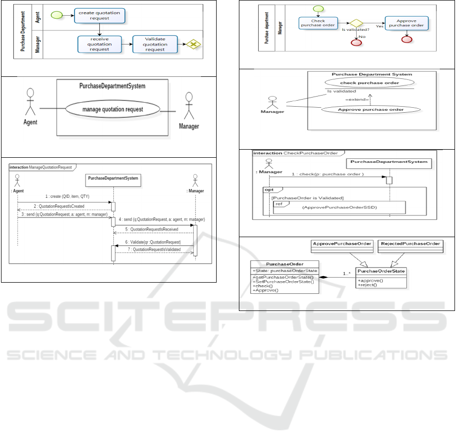
R9. For each fragment F in the BPMN model P:
R9.1. If the fragment is composed of a set of
activities that belong to the same lane, then: 1)
create a use case UC_F with the name of the
first activity SA of F, and 2) add a two-way
association between the actor whose Lane
contains the activity SA and UC_F
R9.2. If one of these activities (A) is defined in
another lane and its name is “receive x" (or any
synonyms of receive), then add a one-way
from UC_F to the Actor (as a secondary actor)
whose Lane contains the activity A, else, add
a two-way association between UC_F and the
Actor (as a secondary actor) whose Lane
includes the activity A (see Figure 7).
R10. Each fragment F composed of only one
activity labeled with :
R10.1. “Send x” or “Send x to y”, its corresponding
use case UC_F will be named “Generate x”;
R10.2. “Receive x” or “Receive x from y”, its
corresponding use case UC_F will be named
“Manage x”; add Y as a primary actor, and
transform the lane including the activity into
secondary actor. The association between
From a BPMN Model to an Aligned UML Analysis Model
629
BPMN model
UCD
SSD
Figure 7: Rule 9.2 illustration.
the use case and the secondary actor is
unidirectional. We note that the information
related to the sender can be found in the
business context of the activity.
R11. If the first activity SA of a fragment F is
labeled “Create x“ then the corresponding use
case UC_F will be named “Manage x”.
R12. For each gateway between two fragments PF
(entry) and NF (exit) such that the activities of
both fragments are in the same lane, add an
<<extend>> relationship from the use case
UC_NF to the use case UC_ PF; and add an
extension named as the first activity's name of
the second fragment (NF.SA) in the use case
of the entry fragment PF ( Figure 8).
R13. For each gateway between two fragments PF
(entry) and NF (exit) such that the activities of
both fragments are in different lanes and:
R13.1. if the name of the first activity of NF is “send
X to Y” and Y is not transformed yet into an
actor, then: 1) create a secondary actor Y; 2)
apply R10.1 to rename the use case UC_NF;
3) add one-way association from UC_NF to
the secondary actor.
R13.2 if NF contains just one activity that is named
“receive X” or “send X”, then delete the use
case UC_NF as well as its associations, and
BPMN model
UCD
SSD
CD
Figure 8: Rule 12 illustration.
its corresponding SSD. Add a two-way
association between UC_PF and the actor
corresponding to NF .
Rules R9, R10, R11, R12, and R13 call and apply
R5, R6 and/or R7 on each activity of the fragment F
to generate the SSD and UC. The succession between
those activities determines the message order.
4 RELATED WORK
In this section, we summarizes existing works on
aligning BPM to IS model.
In (Rhazali et al., 2016), the authors transform any
activity in a BPMN model into a use case in spite of
the different levels of granularity of the modeling
languages.
In (Siqueira and Silva, 2014), the authors propose
a semi-automatic transformation from an enterprise
model to a use case model. The enterprise model is
used as a source of information about the stakeholder
requirements and domain knowledge, while the use
case model is used as software requirements model.
Similar to our approach, (Berrocal et al., 2014)
present a pattern-based and model-driven approach
ICSOFT 2018 - 13th International Conference on Software Technologies
630

for deriving IT system functional models from
annotated business models.
In (Suchenia et al., 2017), the authors describe
how to transform a BPMN model into a UML
sequence diagram. As the UML model natively
supports modeling time issues, the proposed solution
can be used for validating such issues by business
analysts, software engineers, etc.
Cruz et al. (Cruz et al., 2012) propose a set of rules
to generate a data model from the business process
model. Then, the data model may be used as a starting
artifact in the IS software development process.
The approach presented by Meyer et al. (Meyer et
al., 2013) focus on annotated data objects to allow
data dependency representation and data instance
differentiation as well as SQL queries generation
(Przybyłek, 2014) combine techniques from both the
fields of Business Process Engineering and
Requirements Engineering and define a Business-
oriented approach to requirements elicitation.
Overall, the above works related to BP-IS models
in (Meyer et al., 2013) (Rhazali et al., 2016) are purely
structure-based; it ignores the remaining aspects of a
BP, which do affect the performance of a BP. For
example, the type of semantic relations between
classes is not captured, like the composition, heritage,
etc. Furthermore, sequence system diagram is crucial
since it is a popular notation to specify scenarios of the
processing of operations as its clear graphical layout
gives an immediate intuitive understanding of the
system behaviour. Our proposed method combines
both aspects in order to obtain a use case diagram,
sequence system diagrams and class diagram that
cover the structural and semantic aspect. To do so, we
use the business context concept (Section 2.1).
5 CONCLUSION
This paper proposed a transformation-based approach
to generate use case, system sequence and class
diagrams from business process models. It provides
for the generation of IS entities and their relations that
are aligned to the business logic. Compared to
existing works, our approach has the merit of
accounting for both the semantic and structural
aspects of the business process model. To do so, we
proposed to define the business process context
expressing the relation semantics and type.
Ongoing work focuses on 1) conducting an
experimental evaluation to assess the coverage and
precision of all generated use case and system
sequence diagrams; and 2) enhancing the
transformations in order to cover interaction in the
design sequence diagram, and component diagram.
REFERENCES
Aversano, L., Grasso., C., Tortorella, M., 2016. Managing
the alignment between business processes and software
systems. In journal of information and software
technology, v.7 (3). pp. 171-188.
Abrahão, S., Gravino, C., Insfrán, E., Scanniello, G.,
Tortora, G., 2013. Assessing the effectiveness of
sequence diagrams in the comprehension of functional
requirements. In IEEE transactions on software
engineering, v39 (3).pp. 327-342.
Berrocal, J., Garcıa-Alonso, J., Vicente-Chicote, C. &
Murillo, J. M., 2014. A Pattern-Based and Model-
Driven Approach for Deriving IT System Functional
Models from Annotated Business Models. In
Information System Development, pp 319-332.
Cruz, E. F. Machado, R. J., Santos, M. Y., 2012. From
business process modeling to data model: A systematic
approach. In QUATIC’12, 8th Conf. on the Quality of
Information and Communications Technology. Lisbon,
Portugal, 2-6, September, pp.205-210.
ISO/IEC 19510, 2013 ISO/IEC 19510. 2013. Information
technology -- Object Management Group Business
Process Model and Notation.
Khlif W., Ben Ayed N., Almogati E., Ben-Abdallah H.,
''Designing BP-IS aligned models : An MDA-based
Transformation Methodology''. In 13
th
Inter. Conf. on
Evaluation of Novel approaches to software
engineering (ENASE’18), Portugal, March 2018.
Meyer, A., Pufahl, L., Fahland, D., Weske, M., 2013.
Modeling and Enacting Complex Data Dependencies in
Business Processes. In BPM’13,11
th
proceedings of
Inter Conference, vol. 8094, China, August Lecture
Notes in Computer Science 8094, pp. 171-186.
OMG, 2006. The Fast Guide to Model Driven Architecture,
[Online] [Accessed 2017].
Przybyłek, A., 2014. A Business-Oriented Approach to
Requirements Elicitation. In 9
th
Inter. Conf. on
Evaluation of Novel Approaches to Software
Engineering (ENASE 2104), Portugal, 28-30 April.
Rhazali, Y. Hadi, Y. Mouloudi, A., 2016. A Based-Rule
Method to Transform CIM to PIM into MDA. In
International Journal of Cloud Applications and
Computing, IJCAC 6(2).pp.11-24.
Rumbaugh, J., Jacobson, I., Booch, G., 2005. The Unified
Modeling Language Reference Manual. Addison-
Wesley –pp. 742.
Siqueira, F. L. & Silva, P. S. M., 2014. Transforming an
entreprise model into a use case model in business
process systems. In Systems and Software, pp. 152-171.
Suchenia, A., Kluza, K., Jobczyk, K., Wisniewski, P.,
Wypych, M., Ligeza, A., 2017. Supporting BPMN
Process Models with UML Sequence Diagrams for
Representing Time Issues and Testing Models. ICAISC
(2) 2017: 589-598.
Vachharajani, V., Vasant, S., Jyoti, P., 2016. Feasibility
Study of Proposed Architecture for Automatic
Assessment of Use-Case Diagram, In Intern. Conf. on
ICT for Sustainable Development, pp 97-104.
From a BPMN Model to an Aligned UML Analysis Model
631
