
Sliding Mode Control in Mobile Platform Joint Space for Multi-body
Cable Driven Robot
Hachmia Faqihi
1
, Maarouf Saad
2
, Khalid Benjelloun
1
, Mohammed Benbrahim
3
and M. Nabil Kabbaj
3
1
LAII, Ecole Mohammadia d’Ingénieurs, Mohammed V University, Rabat, Morocco
2
Ecole de Technologie Supérieure, Montreal, Canada
3
Sidi Mohamed Ben Abdellah University, Fez, Morocco
Keywords:
Multi-body Cable-driven Robot, Mobile Platform Joint Space, SMC, Sliding Mode Control, Flexibity,
Tensionnability, Constrained Optimization Algorithm.
Abstract:
The aim of this paper is to develop a suitable control of Multi-Body Cable-Driven Robot with satisfactory
tensionnability condition. The desired trajectory is given in joint mobile platform space and thereby trans-
formed on joint actuator space using the developed inverse kinematic. Under the control scheme, the actuator
joint coordinates obtained by the sensor are used as feedback for the control system. Adding to the error in
joint actuator space, the cable tensions which are computed based on the mobile platform dynamic and the
optimization problem are used as inputs of the controller.
The sliding mode control method based on linear reaching law is used to control the effector of the robot.
Asymptotic stability of the closed loop system is analyzed through Lyapunov theorem. Finally, a motion
tracking based on the proposed control strategy is carried out on the Multi Body Cable-Driven Robot. The
obtained results show the effectiveness and the feasiblity of the proposed control method.
1 INTRODUCTION
Cable-Driven Parallel Robots (CDPRs) represents a
class of parallel robots which are becoming increas-
ingly used in several applications, such as industry, re-
habilitation, surgery, rescue, architecture, agriculture
and sport. CDPRs consist of a cables as robot links
connected to an end-effector (mobile-platform) from
one side, and to the winches as the cable drivers fixed
to the base. A suitable cable length motion allows to
move the end-effector in desired position and orien-
tation. Many researchers have been interested to CD-
PRs, by their remarquable advantages. These robots
can be made lighter, stiffer, safer, and more eco-
nomical than traditional serial ones since their flex-
ible structure consists of lightweight and high load-
bearing cables, which make these manipulators con-
venient in different uses. Depending on the design of
the CDPR changes in terms of the number of cables
and their configurations and the end-effector form.
The majority of the studied CDPRs have a single rigid
body end-effector with n Degrees Of Freedom (DOF),
connected to m cables, and few of them had interested
to multi-body end-effector, known as Multi-Body Ca-
ble Driven Robot (MBCDR), where it requires the
more accuracy in design and control. In the design
stage of CDPRs, a suitable cable numbers m and their
configuration should be choosen (S.K.Agrawal and
Y.Mao, 2012), (C.Gosselin and M.Grenier, 2011), to
be able to control the desired n DOF of the used end-
effector, as well as providing the necessary constraints
for the given application. Indeed, as a major issue
in CDPR, the cables can only exert tension and can-
not push the end-effector. Therefore all used cables
should be always in tension in the desired workspace
in order to maintain the rigidity of the systeme, i.e en-
sure a best force distribution in all cables, known as
tensionability condition (wrench closure, or force clo-
sure) (S. Rezazadeh, 2011). The tensile force should
be always met simultaneously in all cables, for mo-
tion planning and control. Control of this kind of
robots has attracted the attention of many researchers,
mainly because of its great impact on the efficiency
of robotic systems. Several control methods have
been proposed for parallel manipulators. However,
only a few of the proposed topologies can be imple-
mented for cable driven parallel manipulators, which
require a hight robustness and accuracy, due to the dy-
Faqihi, H., Saad, M., Benjelloun, K., Benbrahim, M. and Kabbaj, M.
Sliding Mode Control in Mobile Platform Joint Space for Multi-body Cable Driven Robot.
DOI: 10.5220/0006865103570363
In Proceedings of the 15th International Conference on Informatics in Control, Automation and Robotics (ICINCO 2018) - Volume 2, pages 357-363
ISBN: 978-989-758-321-6
Copyright © 2018 by SCITEPRESS – Science and Technology Publications, Lda. All rights reserved
357
namic coupled nonlinear parameters, unmodelled ef-
fects and external disturbances. Most of the proposed
control schemes are based on dynamic model of the
robot, which differs according to the measured param-
eters, those of the actuator space, and those of the mo-
bile platform space (S.Rezazadeh and S.Behzadipour,
2008), (R.Babaghasabha and H.D.Taghirad, 2015),
(T.Madani, 2016), (T.Madani, 2017), (W.Lv and Z.Ji,
2017). In the literature, the major developed con-
trol strategies of CDPR are limited to those with
single rigid body end-effector. Indeed, the clas-
sical control techniques, such as PID, have been
designed (M.A.Khosravi and H.D.Taghirad, 2014),
they are computationally simple but they remain lim-
ited for the nonlinear system properties. Indeed
the lack of the dynamic effects in these controllers
may limit the tracking performance. To improve the
controller performances, nonlinear controller can be
used (R.Babaghasabha and H.D.Taghirad, 2015). Al-
though these control schemes can perform well for in-
dustrial applications, but not for others such as med-
ical applications due to more uncertainties and dis-
turbances. Sliding mode control (SMC), as a vari-
able structure nonlinear control method, has inherent
insensitivity and robustness against uncertainties and
disturbances (V.U.J.Guldner, 1999), (Y.Kali, 2015).
A good design of this controller allows him to be rela-
tively suitable for the control of human robot interac-
tion systems. This area is well-investigated for rigid
bodies, but very little studied for multibodies. Since
in the present application the object driven by the ca-
bles (i.e. the human limb) is a multibody. Therefore,
the objective of this paper is to study a MBCDR, tak-
ing into account all the constraints discussed by the
conventionnel CDPR in addition to its multi body mo-
bile platform constraints, wich lead to a new control
strategy for this type of robots. The proposed con-
troller structure guarantees fully tension forces on the
cables, and it is able to fulfill the stringent position-
ing requirements for these type of manipulators. The
rest of the paper is organized as follows. In section
2 the model of MBCDR is developed in term of the
kinematic and the dynamic. Section 3 the proposed
control strategy for the MBCDR has been described
based on sliding mode method. To check the ef-
fectiveness of the proposed approach, the simulation
tests has been conducted and the results are shown in
section 4. To sum up, section 5 discusses the conclu-
sions and problems for further work.
2 MULTI-BODY CABLE-DRIVEN
ROBOT MODELING
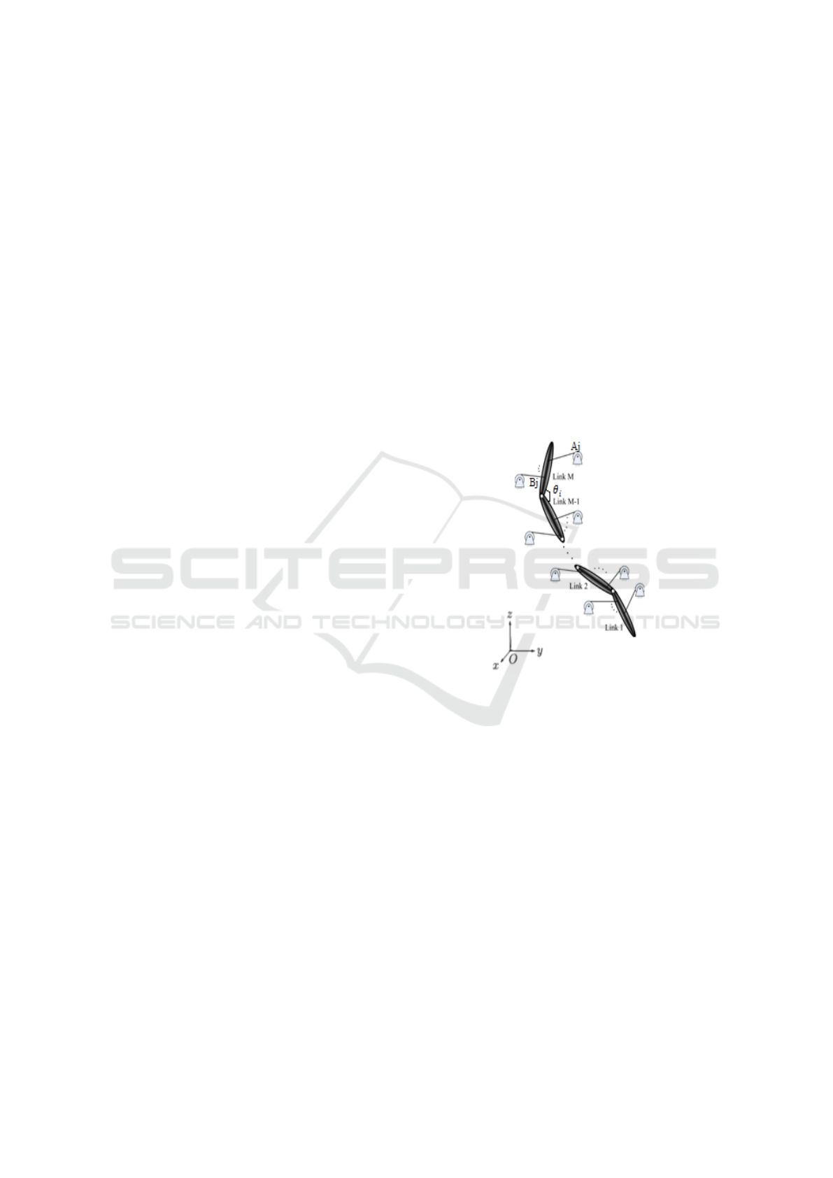
2.1 Robot Description
The general form of multi-body system with M links
constrained by cables is depicted by figure 1. The
multi-body system is considered as a serial configura-
tion with revolute joints. However, the only assump-
tion considered on the multi-body system is that all of
the joints are binary, i.e. they are connected between
two links only. For the multibody cable-driven mech-
anisms, we consider that the multibody has a serial
kinematics and the constraints are holonomic, each
cable is attached from one end to a link and pulled
from the other end by a stationary winch. However,
the concept can be easily extended to more general
joints.
Figure 1: Multi-Body Driven by Cable.
As for CDPR, the main of MBCDR consists on
fixed base where pulleys are attached and mobile plat-
form designed by M articulated links. The cable robot
is a mechanical system that transforms the move-
ments of its actuators into movement of his mobile
platform. In order to analyze the movement of this
mechanism, the following notation is adopted:
- The rotation angles of the motors defined in R
m
are
denoted by q = [q
1
, . . . q
m
], m denoting the number of
actuators.
- The cable lengths defined in R
m
by ρ = [ρ
1
, . . . ρ
m
].
- The platform joint space coordinates defined in R
n
,
are denoted θ = [θ
1
, . . . θ
n
], where n the DOF of the
platform.
- The platform task space coordinates x defined ac-
cordingly to used demensional space.
ICINCO 2018 - 15th International Conference on Informatics in Control, Automation and Robotics
358

2.2 Kinematic Modeling
The Inverse Kinematic (IK) problem for a cable robot,
consist in determining the cable lengths ρ, or the ac-
tuators joint coordinates q, necessary for a given pose
x of the mobile platform.
For the MBCDR, the mobile platform pose x can be
expressed in term of its joint coordinates θ
i
. There-
fore, the IK MBCDR problem refers to find the rela-
tion f between ρ
j
or q
j
and θ
i
, i ∈ [1, . . . n]:
q
j
= f (θ
i
) (1)
Generally the mobile platform pose x are obtained
by adjusting the cable length designated by ρ
j
, j ∈
[1, . . . m]. The cable length represents the distance be-
tween its attachment point A
j
at the fixed structure
and the attachment point B
j
on the mobile platform
defined relatively to the associate reference frame. In
this order the cable length is defined by:
ρ
j
= kx + QB
j
− A
j
k (2)
where Q is the rotation matrix of the mobile platform
frame.
It is assumed that there is a linear relationship be-
tween the cable length ρ
j
and the actuator joint co-
ordinates q
j
expressed in meters and radians, respec-
tively, by:
ρ
j
= ρ
0 j
+ r
j
q
j
(3)
where ρ
0 j
the initial length cable expressed according
the structure geometry, and r
j
is expressed by:
r
i
= κ
j
s
e
2
j
+
p
2
j
2π
(4)
with κ
j
the transmission ratio of the j
th
winder with
the j
th
motor, e
j
and p
j
the radius and the pitch of the
j
th
winder respectively. Note that κ
j
and p
j
are con-
stants.
These equations are defined according to the partic-
ular structure of the robot, and still available in the
case of an inextensible cable and whose winding sys-
tem ensures that e
i
remains constant over time (The
cable does not roll on itself).
However, the mobile platform pose x , is expressed in
its joint space coordinates following the associate ho-
mogeneous transformation matrix, which leads to de-
fine the H(θ
i
) function.
x = H(θ
i
) (5)
Finally the IK is expressed by:
q
j
=
1
r
j
(kH(θ
i
) + QB
j
− A
j
k − ρ
0 j
) (6)
or
q = R
−1
(ρ − ρ
0
) (7)
where R is a diagonal matrix containing the r
i
coefficients such that R = diag{r
1
, r
2
, . . . , r
m
}.
The cable speeds are calculated from the deriva-
tive of the cable length with time, as following:
˙q = R
−1
˙
ρ (8)
The cable accelerations are obtained by taking the
time derivative of equation (8):
¨q = R
−1
¨
ρ (9)
2.3 Dynamic Modeling
2.3.1 Dynamic Actuator Model
The first step for motion control design is to obtain a
dynamic model of the actuators. Due to the fact that
it is much faster compared to the mechanical part, ne-
glecting the dynamics of the electrical part, and also
a first order linear model can be used. The dynamic
model of the actuators associates the vector of motor
torques τ
m
at joint acceleration ¨q. As regards only
the angular accelerations of the motors, we consider
here only the equations of l. It is assumed that mo-
tors, reels and pulleys are cylinders of homogeneous
material.
Each actuator has its elements positioned along a
single axis or two rotational axes. Thus, it is assumed
that the inertia matrices of the various components,
brought to the center of the bound mark to the motor,
are diagonal and positive definite. Therefore, the dy-
namic actuator is defined by equation 10 as following:
τ
m
= I
m
¨q + f ( ˙q) + RT (10)
where I
m
= diag{I
m1
, I
m2
, . . . , I
mm
} is the diagonal
matrix containing the moments of inertia of the m
winders around the axis of rotation of its motor, f ∈
R
m
is the vector of torques due to friction, T is the
vector of cable tensions, and RT ∈ R
m
is a vector rep-
resenting the applied torques by the cables on the ac-
tuator.
In order to express the friction term, the static friction
model is adopted such as (A.Chemori, 2014):
f ( ˙q) = F
s
sign( ˙q) + F
v
˙q (11)
with F
s
and F
v
two diagonal matrices whose traces
are respectively equal to F
s
= tr{ f s1, f
s2
, . . . , f
sm
}
and F
v
= tr{ f
v1
, f
v2
, . . . , f
vm
} where f
s j
and f
v j
re-
spectively denote the coefficients of dry friction (or
Coulomb) and viscous j
th
actuator.
2.3.2 Dynamic Mobile-platform
Applying Newton’s formalism to the platform
(W.M.Spong and M.Vidyasagar, 2006), the dynamic
Sliding Mode Control in Mobile Platform Joint Space for Multi-body Cable Driven Robot
359
equation governing the dynamics of the platform is
written as follows:
M(θ)
¨
θ + N(
˙
θ, θ) = U (12)
With M(θ) and N(
˙
θ, θ) respectively represent the in-
ertia matrix, the centrifugal force matrix and coriolis,
and the matrix of gravitational forces. U is the vector
of the generalized forces corresponding to the gener-
alized coordinates θ.
In order to determine the relationship between the
generated torque U and the cable tensions T , the prin-
ciple of virtual work is used, where δW is the virtual
displacement. Indeed, the cable tensions T will result
in the cable being pulled out by δρ
d
. Then :
δW = T δρ
d
= U δθ (13)
since
δρ
d
=
∂ρ
d
∂θ
δθ (14)
the change of pulled out cable δρ
d
can be related to
the change of cable that remains in the system δρ by:
ρ
d
+ ρ = constant
which gives:
∂ρ
d
∂θ
+
∂ρ
∂θ
= 0 (15)
by substitution
U = −(
∂ρ
∂θ
)
T
T = J
c
(θ)
T
T = W T (16)
where J
c
is the jacobian matrix given by:
J
c
= −
∂(ρ
1
, . . . , ρ
m
)
∂(θ
1
, . . . , θ
n
)
(17)
Finally, the dynamic of MBCDR is expressed by the
coupled following equations:
τ
m
= I
m
¨q + f ( ˙q) + RT
M(θ)
¨
θ + N(
˙
θ, θ) = W T
(18)
3 PROPOSED CONTROL
STRATEGY
The main objective in general motion robot con-
trol is to track a desired trajectory (H.Faqihi and
M.N.Kabbaj, 2016), defined in feasible workspace
with high accuracy even in presence of uncertainties
and external disturbances.
In the proposed control strategy of MBCDR, the
measurement of the actuator articulation joints is
given, and thereby used to close the main loop of
the control system. The objective is to design a ro-
bust controller τ
m
(t) to guarantee the convergence of
the tracking error to zero (q(t) − q
d
(t)) → 0 in finite
time, by ensuring the tensionability of cables during
motion.
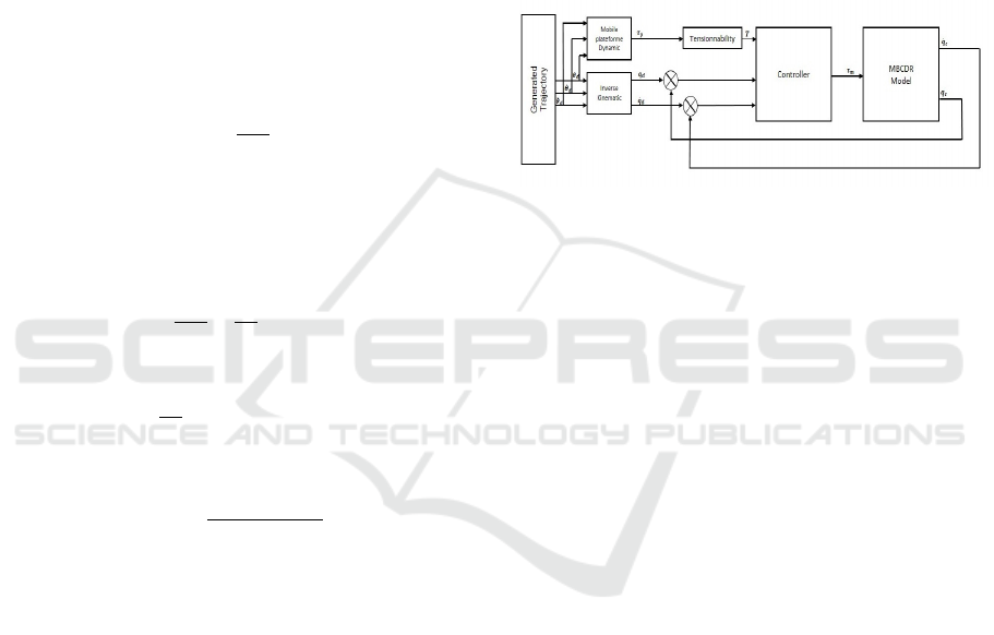
The proposed control strategy is given by the
flowchart Fig.2. The target position and velocity of
the end-effector is set up by using the developed in-
verse kinematic. The error between the measured
value and the target value is regarded as an input of
the control system. The actuator torque is computed
by the sliding mode control and tension distribution
method.
Figure 2: Proposed flowchart control strategy.
3.1 Tensionability Condition
In order to ensure the tensionnability condition of
a cable-driven multibody system, different approach
can be used following the system configuration. The
proposed system is considered as three-link multi-
bodies supported by four cables. Therefore, when
controlling such redundantly actuated CDPR, the
number of tension distributions is infinite. At any
point along a trajectory, there exists an infinity of pos-
sible sets of cable tensions.
From equation (16)
U = J
T
c
T
the number of cables is larger than the DOF of the
system. Then the cable tension is underdetermined.
Since the cables can only pull but not push, it is im-
possible for the tensions in the cables to be negative.
In the actual system, due to the existence of friction
along the cables, the minimum tension in a cable can
be set above a positive value to keep all of the ca-
bles taut. Also, because the motors connected to the
cables can only produce a limited amount of torque,
there may be a maximum limit on cable tensions as
well. Therefore, T can satisfy:
T ∈ (T
min
, T
max
) (19)
Using equations. (16) and (19) as constraints, an opti-
mization problem may be formulated to find a proper
set of cable tensions to generate selected torques.
A quadratic objective function can be used for the op-
timization problem, which minimizes the norm of ca-
ble tension vector. The advantage of using quadratic
ICINCO 2018 - 15th International Conference on Informatics in Control, Automation and Robotics
360

programming over linear programming is that the so-
lution to T will change more continuously when the
Jacobian matrix in the equality constraint of equation
(16) changes, which will help to avoid abrupt changes
in cable tensions when the leg moves from one con-
figuration to another.
Mathematically, the determination of the cable ten-
sions of MBCD can be formulated as follows
(C.Gosselin and M.Grenier, 2011):
min T
T
T
s.t J
c
T = U
and T
min
≤ T ≤ T
max
(20)
The above can be solved using a quadratic program-
ming solver.
3.2 Design of the Control Law
A fast response, insensitivity to parameter variation
and disturbance, and simple physical realization of
sliding mode method allow him to be suitable can-
didate to control the MBCDR in this paper.
Assuming that the kinematics and the desired task
space trajectory are exactly known and away from sin-
gular configuration.
Let define the tracking error and its derivative respec-
tively by:
e(t) = q(t) − q
d
(t) (21)
˙e(t) = ˙q(t) − ˙q
d
(t)
¨e(t) = ¨q(t) − ¨q
d
(t)
where q
d
(t) ∈ R
n
the desired trajectory.
Therefore, using equation (18) yields
¨e(t) = I
m
−1
[τ(t) − f ( ˙q(t)) − RT (t)] − ¨q
d
(t) (22)
In sliding mode control, the variable control systems
are designed to drive and then constrain the system
stable to lie within a neighbourhood of the switching
function. The robust sliding mode control design ap-
proach consists of two components. The first involves
the design of a switching function so that the sliding
motion satisfies design specifications. The second is
concerned with the selection of a control law which
will make the switching function attractive to the sys-
tem state.
In order to maintain the end-effector to track desired
trajectory in the presence of unknown and distur-
bances, the linear sliding surface is defined as:
s(t) = [s
1
(t), . . . , s
m
(t)]
T
= ˙e(t) + λe(t) (23)
where λ = diag{λ
1
, . . . , λ
n
} is a positive definite con-
stant matrix to be selected.
The first derivative of the considered sliding surface,
equation (23), is given in the following from:
˙s(t) = ¨e(t) + λ ˙e(t) (24)
Therefore the continuous equivalent control law that
would achieve ˙s(t) = 0 may be expressed as
τ
eq
(t) = I
m
[ ¨q
d
(t) + λ ˙e(t)] + RT (t) + f ( ˙q(t)) (25)
In order to improve the control performance of slid-
ing control, the reaching law must suitably designed.
A good reaching law can not only weaken chattering
in the system, but also speed up the system sliding
time from any initial state to sliding surface, and im-
prove the robustness of the system. In this paper, the
reaching law is adopted as follows:
τ
sw
(t) = −Ksign(s(t)) − βs(t) (26)
where K > 0, β > 0 and sign(.) represents the sym-
bolic function
sign(s) =
1 s > 0
0 s = 0
−1 s < 0
(27)
Finally:
τ(t) = I
m
[ ¨q
d
(t) + λ ˙e(t) + Ksign(s(t)) + βs(t)] (28)
+RT (t) + f ( ˙q(t))
3.3 Stability of Controlled System
Using the Lyapunov function, the stability analysis
of the proposed robust control law is accomplished.
Defining the lyapunov function as following:
v
m
(t) =
1
2
s
T
(t)s(t) (29)
Then
˙v
m
(t) = s
T
(t) ˙s(t) (30)
˙v
m
(t) = −Ks
T
(t)sign(s(t)) − βs
T
(t)s(t) (31)
From equation (31), we may know that when s(t) > 0,
sign(s(t)) > 0; when s(t) < 0, sign(s(t)) < 0; so
˙v
m
(t) < 0 is always correct, and the system can reach
the sliding mode face in finite time.
Finally, the obtained torque actuator based on the slid-
ing mode controller is given by:
τ = τ
eq
+ τ
sw
(32)
τ = I
m
[ ¨q
d
+ λ˙e + Ksign(s) + βs]RT + f ( ˙q) (33)
Sliding Mode Control in Mobile Platform Joint Space for Multi-body Cable Driven Robot
361

4 SIMULATION RESULTS
To check the effectiveness of the proposed control
scheme in real application, an MBCDR based on three
links as mobile platform is used. The study case ref-
eres to a cable driven robot for locomotor rehabilita-
tion of lower limb (A.Badi and Archambault, 2018).
Firstly, the trajectory is generated in task space,
which represent real rehabilitative motion exercice of
the lower limb end-effector’s, figure 3. The generated
trajectory is after converted in joint space of the mo-
bile platform defined by θ
i
where the physiological
constraints are considered, as discussed in (H.Faqihi,
2017).
Therefore the desired position and velocity joint ac-
0.6
0.8
1
1.2
1.4
1.6
X axis (m)
-2.5
-2
-1.5
-1
Y axis (m)
-1
-0.5
0
0.5
1
Z axis (m)
end effector position in task space
Figure 3: Genrated trajectory in task space.
tuator (q
j
, ˙q
j
) are computed by using the IK equa-
tions developed in section 2. These joint actuator pa-
rameters are used to be input-of the discussed con-
troller, figure 2. On the other hand, the cable ten-
sions are computed from desired trajectory based on
the dynamics of the mobile platform and the defined
constrained optimization problem, following the fixed
constraints T
min
= −70N and T
max
= 70N. The ob-
tained results of cable tensions for the four cables are
given in figure 4. It’s shown that the tensions still lim-
ited in the fixed boundaries.
The obtained cable tensions are used as input of
controller based on sliding mode method to compute
the suitable actuator torque, given in figure 5. The
obtained signal have the cyclic pace according to the
aplied cyclic trajectory.
The used parameters of controller are fixed to
reach tracking trajectory with desired performances
in term of accuracy and response time. The obtained
results for tracking trajectory are given in figure 6
where the tracking position for all the four actuators
are shown.
We note that the computed angle actuators con-
verge to the desired ones after a certain time around
0.075s. Then, the used controller ensures a good
tracking trajectory evaluated by the computed errors
as shown in figure 7.
0 2 4 6 8 10 12 14 16 18 20
time(s)
-60
-40
-20
0
20
40
60
80
Cable tensions (N)
T1
T2
T3
T4
Figure 4: Computed cable tensions.
0 2 4 6 8 10 12 14 16 18 20
time(s)
-3
-2
-1
0
1
2
3
4
Torque actuator (Nm)
1
2
3
4
Figure 5: Obtained Torque.
Figure 6: Tracking Trajectory.
5 CONCLUSION
In this paper, a new sliding mode control strategy of
the Multi-Body Cable-Driven Robot is studied based
on joint actuator space, and tensionnability condition.
ICINCO 2018 - 15th International Conference on Informatics in Control, Automation and Robotics
362
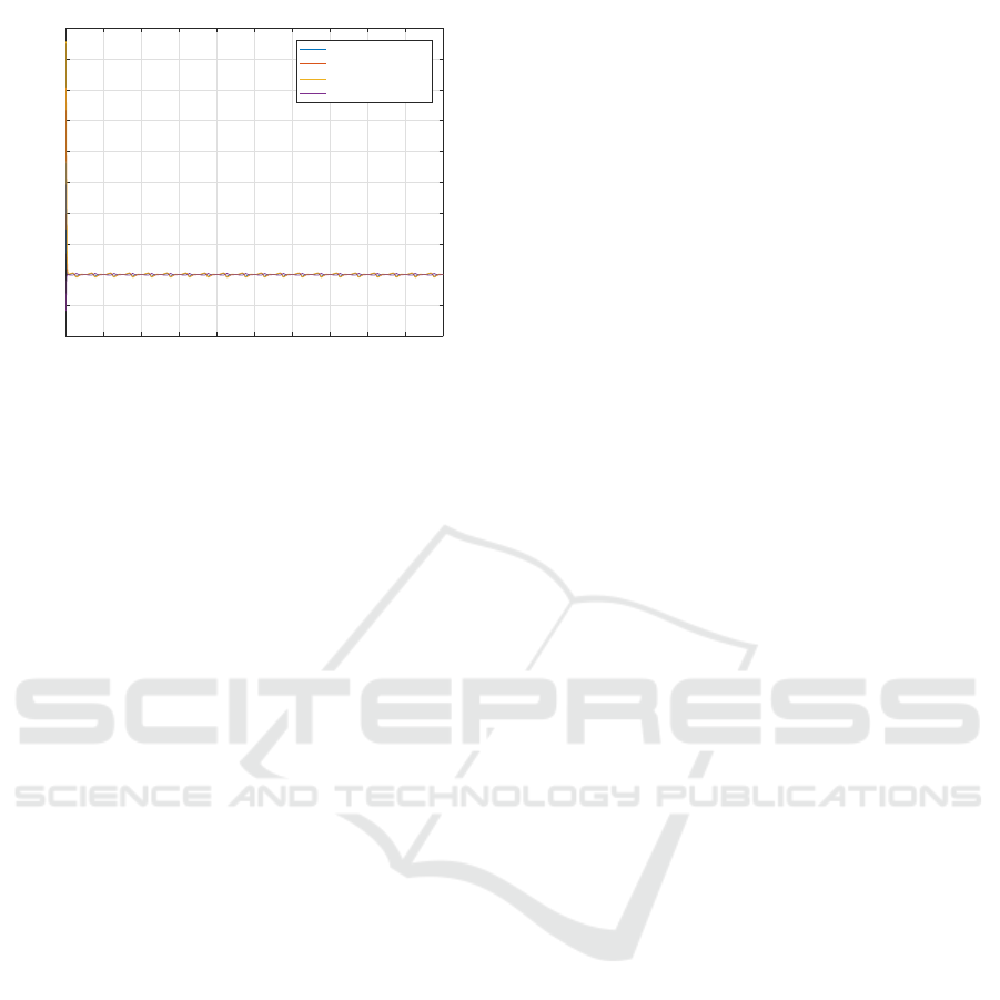
0 2 4 6 8 10 12 14 16 18 20
time(s)
-0.4
-0.2
0
0.2
0.4
0.6
0.8
1
1.2
1.4
1.6
Angle actuator error (rad)
angle actuator error 1
angle actuator error 2
angle actuator error 3
angle actuator error 4
Figure 7: Joint errors.
The robot model is developed taking into account the
cable and the mobile platform flexibilities to describe
the kinematics and the dynamics of the coupled sys-
tem. The proposed control strategy rests on actuator
joint coordinates feedback compared to desired tra-
jectory given in mobile platform joint space and trans-
formed to the actuator joint space. The obtained error
is used to design the sliding control law. As prin-
cipal issue of cable robot is to ensure the cable ten-
sionnability during motion. In this order, constrained
optimization algorithm is developed based on mobile
platform dynamics. The cable tensions are computed,
and thereby used as another input of controller. The
stability of the proposed controller is discussed based
on Lyapunov function.
To validate the feasibility and the effectiveness of
the Multi-Body Cable Driven Robot control, a ref-
erence trajectory is generated to move all the mo-
bile platform degrees of freedoms, and thereby, ap-
plied to the proposed conltrol strategy. Using suitable
gains controller, the simulation results have presented
a good motion tracking.
The present study can be improved by introduc-
ing into the controller, a cable tension feedbacks via
the use of the appropriate sensors or by solving the
Forward Kinematic of the Multi-Body Cable Driven
Robot. if the main is to incorporate the dynamic of
system
ACKNOWLEDGMENT
This work has been supported by Automatic and In-
dustrial Informatics Laboratory (LAII), Ecole Mo-
hammadia dŠIngenieurs, Mohammed V University,
Rabat, Morocco; Integration of Systems and Ad-
vanced Technologies Laboratory (LISTA), Sciences
Faculty, Fes, Morocco; The Department of Electrical
Engineering, Ecole de Technologie Superieure, Mon-
treal, Canada.
REFERENCES
A.Badi, M.Saad, G. and Archambault, P. (2018). A ca-
ble driven robot for locomotor rehabilitation of lower
limb. PCT/CA2016/051376, WO 2017/088055 A1.
A.Chemori, G. El-Ghazaly, M. G. V. C. (2014). Adap-
tive terminal sliding mode control of a redundantly-
actuated cable-driven parallel manipulator: Cogiro.
Springer, Proceedings of the Second International
Conference on Cable- Driven Parallel Robots.
C.Gosselin and M.Grenier (2011). On the determination of
the force distribution in overconstrained cable-driven
parallel mechanisms. Meccanica, 46.
H.Faqihi, M.Saad, K.-M. and M.N.Kabbaj (2016). Track-
ing trajectory of a cable-driven robot for lower limb
rehabilitation.
H.Faqihi, M.Saad, K.-M. M. (2017). Optimization algo-
rithm for an exoskeleton robotic inverse kinematic ap-
plication. Lecture Notes in Electrical Engineering.
M.A.Khosravi and H.D.Taghirad (2014). Robust pid con-
trol of fully-constrained cable driven parallel robots.
Mechatronics, 24.
R.Babaghasabha, M. and H.D.Taghirad (2015). Adaptive
robust control of fully-constrained cable driven paral-
lel robots. In Mechatronics, volume 25.
S. Rezazadeh, S. B. (2011). Workspace analysis of multi-
body cable-driven mechanisms. Journal of Mecha-
nisms and Robotics ASME.
S.K.Agrawal and Y.Mao (2012). Design of a cable-
driven arm exoskeleton (carex) for neural rehabilita-
tion. IEEE Transactions on Robotics, 28.
S.Rezazadeh and S.Behzadipour (2008). Impedance con-
trol of cable driven mechanisms. In Proceedings of
International Design Engineering Technical Confer-
ences and Computers and Information in Engineering
Conference IDETC/CIE.
T.Madani, B.Daachi, K. (2016). Non-singular terminal slid-
ing mode controller: Application to an actuated ex-
oskeleton. Mechatronics, 33.
T.Madani, B.Daachi, K. (2017). Modular-controller-design-
based fast terminal sliding mode for articulated ex-
oskeleton systems. IEEE Transactions on Control Sys-
tems Technology, 25.
V.U.J.Guldner, J. (1999). Sliding mode control in elec-
tromechanical systems. Taylor-Francis.
W.Lv, L. and Z.Ji (2017). Sliding mode control of cable-
driven redundancy parallel robot with 6 dof based on
cable-length sensor feedback. Mathematical Prob-
lems in Engineering, 17.
W.M.Spong, S. and M.Vidyasagar (2006). Robot modeling
and control. ohn Wiley & Sons.
Y.Kali, M.Saad, K. M. (2015). Sliding mode with time delay
control for mimo nonlinear systems with unknown dy-
namics. Recent Advances in Sliding Modes (RASM).
Sliding Mode Control in Mobile Platform Joint Space for Multi-body Cable Driven Robot
363
