
The Topological Functioning Model as a Reference Model for
Software Functional and Non-functional Requirements
Erika Nazaruka and Jānis Osis
Department of Applied Computer Science, Riga Technical University, Sētas iela 1, LV-1048, Riga, Latvia
Keywords: Topological Functioning Model, Functional Requirements, Non-functional Requirements, Requirements
Modelling.
Abstract: Specification of non-functional requirements in models is a challenge due to extra-functional nature of the
requirements. The topological functioning model (TFM) can serve as a reference model for specifying
mappings from both functional and non-functional requirements to the functional characteristics and structure
of the modelled system. The main principle presented in this paper extends a way of specification of the TFM
functional characteristics and causal relationships and provides a specification of mapping types as tuples of
TFM functional features extended with requirements and characteristics of these relationships, namely,
completeness and overlapping for functional requirements, and scope and dynamic characteristics for non-
functional ones. This allows propagating the mappings from requirements to software implementing
constructs, that would be useful for further architectural decisions and development of test cases.
1 INTRODUCTION
Software is everywhere, but software development
projects fail very often (Charette 2005). Inadequate,
incomplete, constantly changing software
requirements remain one of the main risks in the
software development.
Software requirements specify the required
functionality of the planned product as well as quality
attributes, constraints and external interface
requirements (Wiegers and Beatty 2013). The last
three are called non-functional requirements (NFRs).
NFRs show how well the required functionality must
be implemented. The quality attributes or “-ilities”
constitute a large part of NFRs. NFRs sometimes are
called also extra-functional requirements. According
to Wiegers and Beatty (2013), external quality
attributes are availability, installability, integrity,
interoperability, performance, reliability, robustness,
safety, security, and usability.
The functional requirements (FRs) are
implemented as functional entities, while
implementation of NFRs may differ corresponding to
their nature (Liu et al. 2010) – they can contain
technical information that relates to functional
requirements, system architecture, design constraints,
as well as implementation constraints (Wiegers and
Beatty 2013).
A Topological Functioning Model (TFM)
elaborated at Riga Technical University, Latvia, in
1969 by Janis Osis (Osis and Asnina 2011c) specifies
a system from three viewpoints – functional,
behavioural and structural. This model can serve as a
root model for further analysis of the system and
software domains and as a reference model for
system/software requirements. Its main distinction
from other models is formalism based on the
algebraic topology and system theory. The formalism
does not worsen holistic representation of the system
in comparison with semi-formal modelling languages
used nowadays, such as UML (Unified Modelling
Language) or BPMN (Business Process Model and
Notation). The modelled facts and knowledge about
the system can be hold in different forms, e.g. as
tuples of elements or a knowledge base, thus allowing
controlled transformations from one view to another.
Besides that, it is possible to create a model of the
sub-system, e.g. a model of the supporting
information system or a software system, and to keep
consistency between models of the system and its
sub-systems in the mathematically formal way as well
as to verify completeness and consistency of the
gathered knowledge.
FRs can be mapped directly onto the TFM, thus
leading to discovering incompliances between
determined FRs and functional characteristics of the
domain. Similarly, all NFRs can be mapped into the
Nazaruka, E. and Osis, J.
The Topological Functioning Model as a Reference Model for Software Functional and Non-functional Requirements.
DOI: 10.5220/0006811204670477
In Proceedings of the 13th Inter national Conference on Evaluation of Novel Approaches to Software Engineering (ENASE 2018), pages 467-477
ISBN: 978-989-758-300-1
Copyright
c
2019 by SCITEPRESS – Science and Technology Publications, Lda. All rights reserved
467

TFM, indicating the scope and dynamical
characteristics of the requirements.
This paper summarizes the results of research
work on system/software requirements specification
and verification by means of the TFM. All cases are
explained using small examples.
The paper is organized as follows. Section 2
describes main features of the TFM and its
application in the field of functional requirements.
Section 3 summarizes the mentioned results on
referencing NFRs to this model. Section 4 gives the
illustrating example. Related work (Section 5) and
conclusions (Section 6) end the paper.
2 TFM AS A REFERENCE
MODEL FOR FUNCTIONAL
REQUIREMENTS
The TFM is a formal mathematical model that allows
modelling and analysing functionality of the system
(Osis and Asnina 2011c). It could be a business,
software, biological system, mechanical system, etc.
The TFM represents the modelled functionality as a
digraph (X, Θ), where X is a set of inner functional
characteristics (called functional features) of the
system, and Θ is a topology set on these
characteristics in a form of a set of cause-and-effect
relations. TFM models can be compared for
similarities using a continuous mapping mechanism
(Asnina and Osis 2010). Since 1990s the TFM is
being elaborated for the software development (Osis
et al. 2008a).
The TFM is characterized by the topological and
functioning properties (Osis and Asnina 2011b). The
topological properties are connectedness,
neighbourhood, closure and continuous mapping.
The functioning properties are cause-and-effect
relations, cycle structure, inputs and outputs. The
composition of the TFM is presented in (Osis and
Asnina 2011c).
Rules of composition and derivation of the TFM
from the textual system description within
TFM4MDA (TFM for Model Driven Architecture) is
provided by examples and described in detail in
several publications (Asnina 2006; Osis et al. 2007;
Osis et al. 2008b). The TFM can be manually created
in the TFM Editor or can also be generated
automatically from the business use case descriptions
in the IDM toolset (Šlihte and Osis 2014).
The main TFM construct is a functional feature
that represents system’s functional characteristic,
e.g., a business process, a task, an action, or an
activity (Osis and Asnina 2011b). It can be specified
by a unique tuple (1).
<A, R, O, PrCond, PostCond, Pr, Ex>
(1)
Where (Osis and Asnina 2011c):
A is object’s action,
R is a set of results of the object’s action (it is
an optional element),
O is an object that gets the result of the action
or a set of objects that are used in this action,
PrCond is a set of preconditions or atomic
business rules,
PostCond is a set of post-conditions or atomic
business rules,
Pr is a set of providers of the feature, i.e.
entities (systems or sub-systems) which
provide or suggest an action with a set of
certain objects,
Ex is a set of executors (direct performers) of
the functional feature, i.e. a set of entities
(systems or sub-systems) which enact a
concrete action.
The cause-and-effect relations between functional
features define the cause from which the triggering of
the effect occurs. The formal definition of the cause-
and-effect relations and their combinations are given
in (Asnina and Ovchinnikova 2015). It states that a
cause-and-effect relation is a binary relationship that
links a cause functional feature to an effect functional
feature. In fact, this relation indicates control flow
transition in the system. The cause-and-effect
relations (and their combinations) may be joined by
the logical operators, namely, conjunction (AND),
disjunction (OR), or exclusive disjunction (XOR). The
logic of the combination of cause-and-effect relations
denotes system behaviour and execution (e.g.,
decision making, parallel or sequential actions).
The TFM can be manually (but according to the
precise rules) transformed into most used UML
diagram types (Figure 1): class diagrams, activity
diagrams, use cases and their textual specifications
(Osis and Asnina 2011a) and Topological UML
(Donins et al. 2011) diagrams such as Topological
Class diagrams, Topological Use Case diagrams,
Activity diagrams, State Chart diagrams, Sequence
and Communication diagrams (Osis and Donins
2010).
Since the TFM specifies functioning of the
system, it can be used for verification of FRs. The
FRs can be mapped onto the TFM functional features
(Figure 1) as described in detail in (Osis and Asnina
2008b; Osis and Asnina 2008a; Asnina et al. 2011).
As a result, mappings give the opportunity to find
MDI4SE 2018 - Special Session on Model-Driven Innovations for Software Engineering
468

incomplete, additional, conflicting, unnecessary, as
well as redundant requirements to the system
functionality.
ReaderAccount ReaderCard
Reader Fine
BookCopyBookFundRequest
Library IS
Librarian
Register reader
Check out book
Return book
Close fine
Identify Reader
«uses»
«uses»
«uses»
11
20
16
19
15
18
13
14
12
9
7
8
6
1 2 3
4
5
10
17
SG1 “Register a reader”,
SG2 “Check out a book”,
SG3 “Return a book”,
SG4 “Pay a fine”,
SG5 “Impose a fine”,
SG6 “Close a fine”.
FR1: The system shall register a new reader;
FR2: The system shall check out a book copy;
FR3: The system shall handle return of a book copy;
FR4: The system shall account reader’s fines.
System goals
Functional requirements
UML Class
Diagram
UML Use Case Diagram and
Specifications
Topological Functioning Model
Mappings
Mappings
Mappings
Mappings
Generate
Generate
Figure 1: Mappings from analysis artefacts to the TFM;
some artefacts can be generated from the TFM.
Types of FRs mappings onto the TFM can be one-
to-zero, one-to-one, one-to-many, many-to-many,
many-to-one, and zero-to-one:
One-to-one is when one functional requirement
completely maps onto one functional feature;
this means that the functional requirement
completely specifies one functional
characteristic of the domain, for example,
authorization of a registered user.
One-to-many, many-to-many and many-to-one
cases relate to situations when specifications of
functional requirements and functional
characteristics are too decomposed. One-to-
many and many-to-one are special cases of the
relation type “many-to-many”. These cases can
be caused by different levels of details between
functional requirements and TFM functional
features. Such cases indicate and help in
discovering decomposed, overlapping or
incomplete requirements.
One-to-zero and zero-to-one. The former
occurs when one functional requirement
describes new (or undefined) functionality of
the system that can cause modification of the
system and its TFM. The latter occurs when the
requirements specification does not contain
any functional requirement corresponding to
the already defined functional characteristics.
This can indicate the functionality that either
will not be implemented in the “target” system
or it is new (and thus it requires changes in the
existing processes of the system), or missed
(i.e., either it is not mentioned in the
requirements specification, or it will be
changed but it is not explicitly expressed).
The mappings from FRs to the TFM are specified
in instances of the meta-class Correspondence (Osis
and Asnina 2011c).
3 TFM AS A REFERENCE
MODEL FOR
NON-FUNCTIONAL
REQUIREMENTS
3.1 Specification of Mappings
Specified as tuples, the mappings between
requirements and TFM functional features can be
reversed and specified as references from the TFM to
FRs. They can be added to the specification tuple (1)
of the functional feature as shown in (2).
<A, R, O, PrCond, PostCond, Pr, Ex, FRs>
(2)
Where FRs is a set of references to functional
requirements specified separately from the TFM.
NFRs similarly to FRs can be mapped onto the
TFM functional feature or a set of features by
providing referencing in a way similar to the
specification of the corresponding FRs.
The possible types of NFRs mappings onto the
TFM are the same as in case of FRs, i.e. one-to-zero,
one-to-one, one-to-many, many-to-many, many-to-
one, and zero-to-one, but the meaning differs:
One-to-one is when one non-functional
requirement is related to the concrete
functional feature and must be implemented in
the corresponding entities. For example, a
functional feature specifies retrieving of all
loans for some time period from the database
and a non-functional feature specifies that the
accomplishment of the request must not exceed
3 milliseconds.
One-to-many is when one non-functional
requirement is related to all noted functional
features and must be implemented in all the
corresponding entities. For example, there are
several functional features that specify
The Topological Functioning Model as a Reference Model for Software Functional and Non-functional Requirements
469

retrieving data from the database and some
successive calculations, and a non-functional
feature that specifies that accomplishment of
the requests to the database must not exceed 3
milliseconds.
Many-to-one is when more than one non-
functional requirements are related to one
noted functional feature and must be
implemented in the corresponding entities. It
could be considered as a special case of the
many-to-many relationship. For example, there
are two non-functional features that specify the
requirement to the language of the user
interface and the requirement to the provided
software interface. Both must be implemented
in the input functional feature that specifies
interaction with the users of software.
One to zero. One non-functional requirement is
not related to any functional feature and is not
traceable in the model and in the code. This
indicates that this requirement is out of the
scope of the model and, hence, out of the scope
of the system planned. There could be two
causes, i.e., either the requirement is not
appropriate, or the model lacks the required
functionality. The latter may indicate
incomplete analysis of the required functions
that are new for the system where software will
run.
Zero to one. A functional feature is not related
to any non-functional requirement. It is a
reason to recheck the non-functional
requirements.
The mappings between NFRs and the TFM
functional features can also be specified in the tuple
as element NRFs – a set of references from a
functional feature to NFRs (3).
<A, R, O, PrCond, PostCond, Pr, Ex, FRs, NFRs>
(3)
Besides that, NFRs may be referenced only from
those functional features that have references to FRs,
since as FRs relate to functionality that will be
implemented as NRFs relate to the same one.
Quantitative characteristics of NFRs can also be
added to the specification of a functional feature in
the TFM. All that is needed is to extend an element of
set NFRs that will describe the needed characteristics
value or limit D (4).
NFRs = {NFR
1
, …, NRF
n
},
where NFR
i
= <REF
NFRi
, D
NFRi
, SC
NFRi
>
(4)
For example, if non-functional requirement NFR1
has a dynamic characteristics D that can be expressed
as a value or as a function (e.g. D=f(p), where p is a
parameter set of some function f). Thus, it could be
added to the tuple of the functional feature
specification in a form NFRs = {NFR1}, where
NFR1=<REF
NFR1
, D
NFR1
> and REF
NFR1
is a reference
to the NFR1.
Scope of non-functional requirements may be a
process, a persistent data, or a whole system. This list
may be extended by values specific to the project. In
the element specification (4), this value can be
indicated as a value of variable SC
NFRi
that
corresponds to the enumeration {“process”,
“persistent data”, “whole system”}.
Indeed, this specification is not as compact as
instances of meta-class Correspondence (since most
of NFRs refers to the whole system), but it is still
formal and accurate.
However, to provide compactness, another
specification that would hold knowledge of meta-
class Correspondence may be introduced for both FRs
and NFRs. Let us assume that we have a functional
feature tuple FF (5) with additional element “id” that
denotes an identifier of a FF.
FF = <id, A, R, O, PrCond, PostCond, Pr, Ex>
(5)
Then it is possible to specify mappings FR2FF (6)
from FRs to functional features FFs like in meta-class
Correspondence, where FR is a set of functional
requirements, FF is a set of functional features, and
isComplete and isOverlapping are Boolean variables
for indicating complete or overlapping mappings.
FR2FF = < FR, FF, isComplete, isOverlapping>
(6)
In case of NFRs mappings can be specified as a
tuple (7), where NFR is a set of non-functional
requirements in the form indicated in (4), and FF is a
set of functional features.
NFR2FF = < NFR, FF>
(7)
In general, the TFM and mappings from
requirements onto it can be described as in (8).
TFM2R = {FF, NFR, FR, FR2FF, NFR2FF}
(8)
MDI4SE 2018 - Special Session on Model-Driven Innovations for Software Engineering
470

3.2 Propagating to Implementing
Constructs
Certainly, specification of mappings is useless
without its further use. Table 1 illustrates summary of
traceability of TFM elements to elements of software
architecture expressed in terms of modelling
constructs of Unified Modelling Language (Donins
2012).
Table 1: Tracing TFM elements into elements of software
architecture.
Elements in
TFM
Implementing constructs in UML
Action
Activities, operations, messages, events,
entry and exit effects
Object
Classes, objects
Result
Classes, objects, states, associations
between certain classes
Precondition
Guards in behavioural diagrams, states
Postcondition
States
Providers
Actors, subject, classes
Executors
Actors, classes, objects
Subordination
None
Cause-and-
effect relation
Topological relationships, structural
relationships, control flows, transitions
Functioning
cycle
Topological relationships, structural
relationships, control flows
TFM itself
Subsystems or subjects; use cases, actors
and relationships between them; objects,
messages and their sequences;
workflows; topological class diagrams,
topological use case diagram,
communication diagrams, and object
diagrams; state diagrams; component and
deployment diagrams
In general, requirements traceable to TFM
functional features and cause-and-effect relations are
traceable to the corresponding behavioural (e.g., an
activity, a control flow) and structural constructs
(e.g., a class) in UML diagrams that may be verified
at different modularization levels starting from units
and finishing by sub-systems or large modules. Thus,
NFRs (as well as FRs) can be designed and tested in
the corresponding structural and behavioural
constructs of UML diagrams such as classes, objects,
activities, processes, events, sub-systems,
components and so on and in the constructs of source
code such as persistent (serializable) classes, methods
and functions, processes, modules and assemblies,
components and subsystems, etc.
4 ILUSTRATIVE EXAMPLE
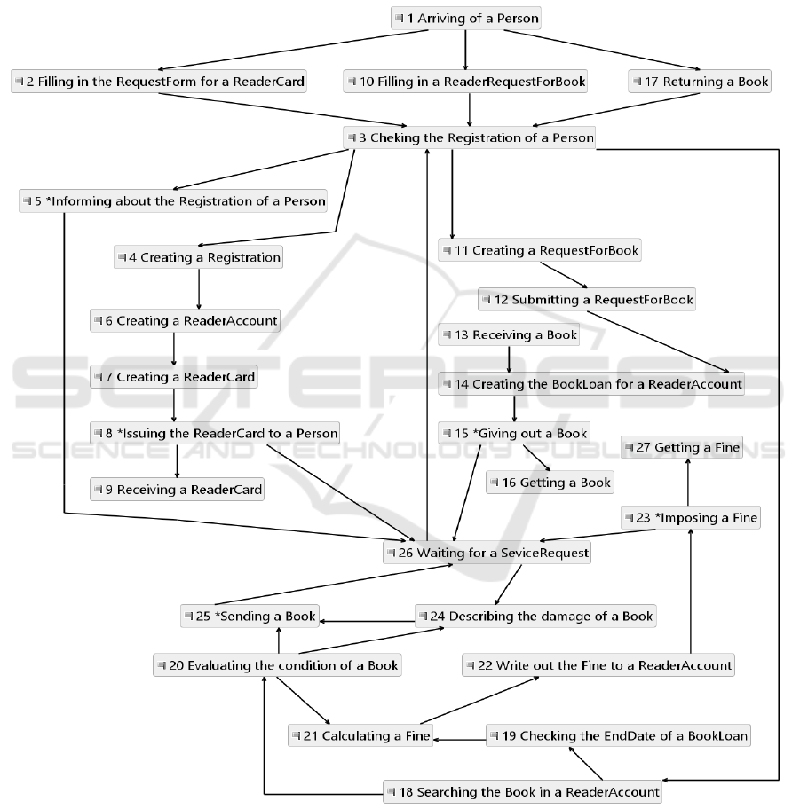
Let us consider the example of the TFM for a library
system. The TFM (Figure 2) specifies the main
functionality provided by the library, i.e. registering
persons as readers, and giving out and taking back the
books as well as imposing a fine in case of damages
of the book or the exceeded loan time. The
specification of functional features is given in Figure
3 and Figure 4. Let us assume that the task is to create
new software that should support librarians’ work.
Software functional requirements to the new system
are stated as follows:
FR1: The system shall provide registration of a
new reader by creating a reader account and
issuing a reader card to the registered person.
FR2: The system shall provide giving out a
book to the reader.
FR3: The system shall provide the return of a
loaned book to the library.
FR4: The system shall show information of the
reader’s registration to the librarian.
FR5: The system shall provide generation of a
report on lost books for the indicated time
period.
FR6: The system shall provide generation of a
report on damaged books for the indicated time
period.
Software non-functional requirements are the
following:
NFR1: The user interface language must be
Latvian.
NFR2: The search for a reader account must
not exceed 2 seconds.
NFR3: The system must be available from 8 to
20 o’clock from Monday to Friday.
NFR4: All activities of the software user must
be logged.
NFR5: The system must create a backup for all
data.
NFR6: The software must support
simultaneous work of 10 users.
References from TFM functional features to the
FRs and NFRs are shown in Figure 5.
Summarizing, in the example we have one-to-
many, zero-to-one, and one-to-zero relationships
among functional requirements and functional
features. The one-to-many relationships are FR1 to
functional features 2, 3, 4, 5, 6, 7, 8; FR2 to 3, 11, 12,
13, 14; FR3 to 3, 18, 19, 20, 21, 22, 23, 24, 25; FR4
to 3, 5. The zero-to-one relationships relate to
functional features 1, 9, 10, 15, 16, 17, 26, and 27.
The one-to-zero relates to FR5 and FR6. The latter
The Topological Functioning Model as a Reference Model for Software Functional and Non-functional Requirements
471
case indicates new functionality that must be
introduced into software to be built and is not
represented in the TFM of the current functioning of
the library. This means that the TFM must be
extended with several functional features that
represents the required functional characteristics and
revalidated. Then, FR5 and FR6 should be mapped to
the new functionality.
In their turn, NFRs relate to functional features
(related to FRs) with one-to-many and one-to-one
relationships. So, NFR1, NFR3, NFR4 and NFR6
relate to the whole system (as to processes, as to data),
NFR2 relates to functional feature 3, and NFR5 also
relates to the whole system, but only to the persistent
data.
Figure 2: The topological functioning model of the library operation (simplified).
MDI4SE 2018 - Special Session on Model-Driven Innovations for Software Engineering
472
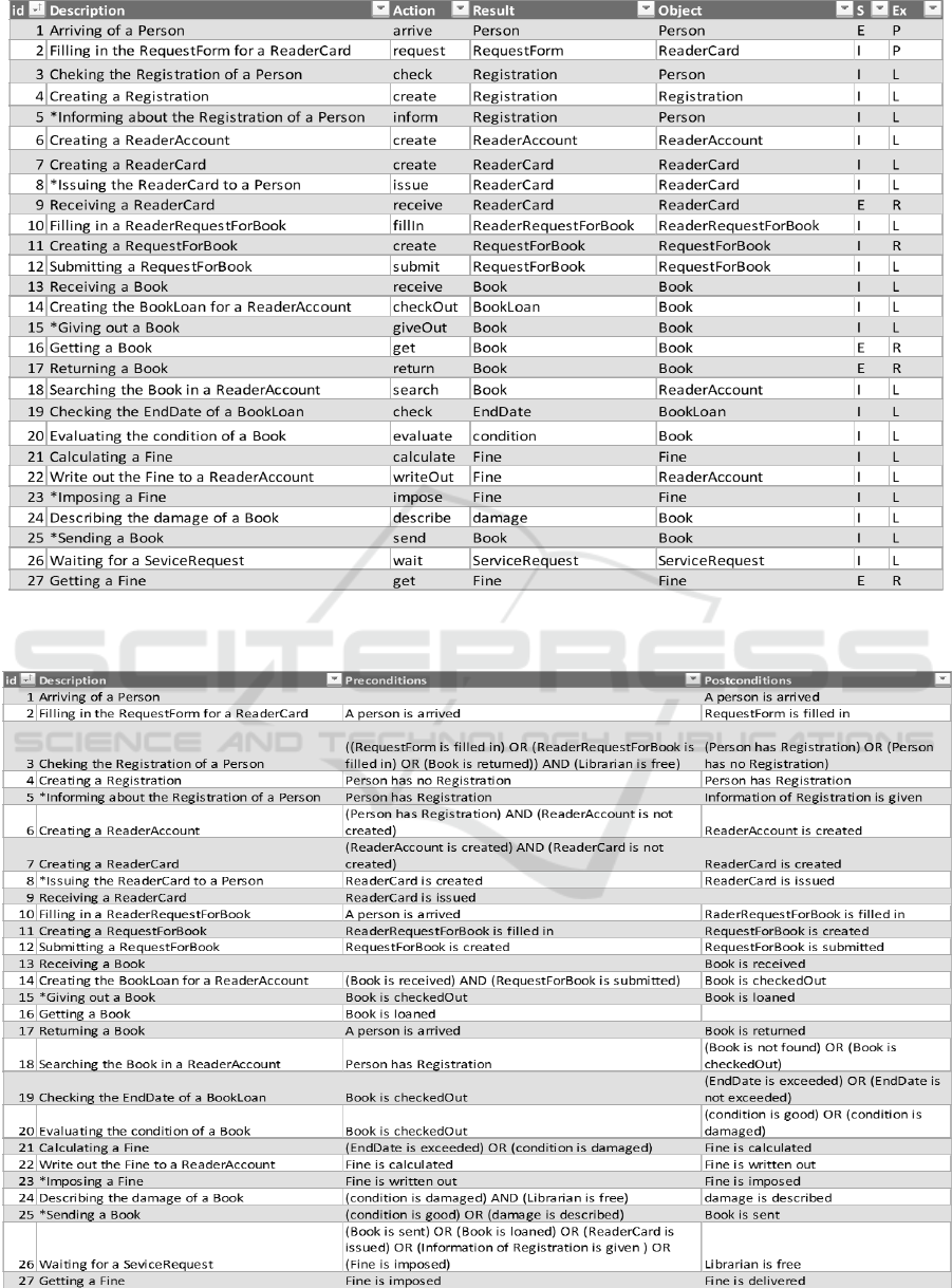
Figure 3: The specification of TFM functional features, where S – subordination, I – inner of the system, E – external to the
system, Ex – the executor, R – the reader, L – the librarian, P – the person.
Figure 4: The specification of TFM functional feature preconditions and post-conditions.
The Topological Functioning Model as a Reference Model for Software Functional and Non-functional Requirements
473
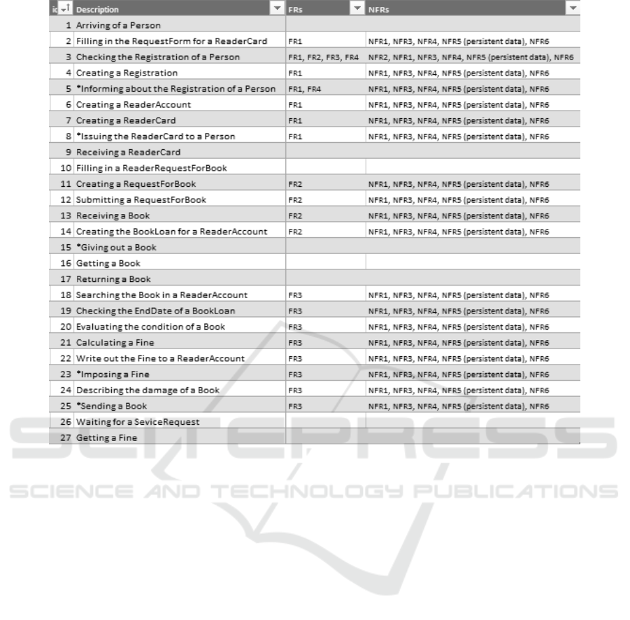
Figure 5: The specification of mappings between TFM functional features and both functional (FRs) and non-functional
requirements (NFRs).
In other words, FR1 is a requirement of
implementation of the process of the registration of a
new reader, where a user interface must be in Latvian
(NFR1), time required for searching a reader account
must not exceed 2 seconds (functional feature 3,
NFR2), this process must be available from 8 to 20
o’clock from Monday to Friday (NFR3), all user
activities must be logged (NFR4), it must process at
least 10 simultaneous requests (NFR6), and backups
of data of persistent classes ReaderCard,
RequestForm, Registration, Person, and
ReaderAccount must be created (NFR5).
FR2 is a requirement of implementation of the
process of loaning books, where a user interface must
be in Latvian (NFR1), time required for searching a
reader account must not exceed 2 seconds (functional
feature 3, NFR2), this process must be available from
8 to 20 o’clock from Monday to Friday (NFR3), all
user activities must be logged (NFR4), this process
must support 10 simultaneous requests (NFR6), and
create a backup data of persistent classes
Registration, Person, RequestForBook, Book, and
BookLoan (NFR5).
FR3 is a requirement of implementation of the
process of returning loaned books, where a user
interface must be in Latvian (NFR1), time required
for searching a reader account must not exceed 2
seconds (functional feature 3, NFR2), this process
must be available from 8 to 20 o’clock from Monday
to Friday (NFR3), all user activities must be logged
(NFR4), this process must support 10 simultaneous
requests (NFR6), and create a backup data of
persistent classes Registration, Person, Book,
ReaderAccount, BookLoan and Fine (NFR5).
FR4 is a requirement of implementation of the
process of informing registration data, where a user
interface must be in Latvian (NFR1), time required
for searching a reader account must not exceed 2
seconds (functional feature 3, NFR2), this process
must be available from 8 to 20 o’clock from Monday
to Friday (NFR3), all user activities must be logged
(NFR4), this process must support 10 simultaneous
requests (NFR6), and create a backup data of
persistent classes Registration and Person (NFR5).
FR5 and FR6 speicify new functionality that must
be first added to the TFM, then the TFM must be
MDI4SE 2018 - Special Session on Model-Driven Innovations for Software Engineering
474

revalidated, and the necessary NFRs must be
referenced to the introduced functional features.
Concluding, TFM as a reference model allows
showing required functionality and its extra-
functional characteristics already at the stage of
problem/solution domain modeling and analysis.
5 RELATED WORK
Modelling and further analysis of NFRs in the context
of Requirements Engineering and early stages of
Model Driven Software Development (MDSD) is
quite actual at the present.
Liu et al. provide their own solution based on
analysis of FRs implementation in use case, class and
sequence diagrams (Liu et al. 2010). Analysis of
these diagrams allows authors to annotate
corresponding constructs in the diagrams and to use
them as root nodes for creation of a soft goal graph
with NFRs. Then the soft goal graph is refined to sub-
NFRs. Operationalizations for these sub-
requirements are identified in the corresponding
sequence and class diagrams. Potential conflicts and
synergy are identified during this process, too. At the
result, two models are created, namely, functional and
non-functional. These models are integrated using
JointPoint elements. However, as the authors
mention, the suggested approach is mainly suitable
for NFRs that are closely related to the functionality.
Besides that, a quantitative part of NFRs is not
modelled.
The same conception of soft goal graphs is applied
in (Xiang et al. 2015), (Ahmad et al. 2012) and
(Zubcoff et al. 2016), etc. The first authors introduce
their own ontology-based language for NFRs
specification. The reason is to model NFRs and
analyze possible conflicts among them as early as
possible at the development. The authors illustrate
that a use of ontology in NFRs modeling is one of
current trends in requirements modeling and analysis.
Similarly to our approach, specifications of NFRs and
FRs relate to each other. The difference is in a
referencing model, the authors use the soft goal
interdependency graph, while in our approach we
make a use of the TFM. Ahmad et al. (Ahmad et al.
2012; Ahmad et al. 2015) use the KAOS based
approach with domain specific language that extends
special requirements specification language Relax. In
their turn, the latter authors apply Pareto Efficiency to
optimize NFRs satisfaction and as a reference model
they use the i* (i-star) [soft goal] model.
Extended NFRs framework based on the soft goal
model (Goncalves and Krishna 2015) suggest an
approach, where weights are added on edges between
parent and child goals, thus allowing dynamic
analysis of the possible design alternatives for soft
goal satisfaction by agents.
Phalnikar and Jinwala provide a simple
framework for Service-Oriened Requirements
Engineering that uses the semi-formal approach of
graph transformation and transformation of WSDL
(Web Service Definition Language) specifications in
XML into GGX (Graph Grammar Language) format
(Phalnikar and Jinwala 2015). As a result, analysis of
critical pairs of requirements is conducted. This
approach apply the similar idea that NFRs must be
specified as addition to behavioural and structural
diagrams of the system model.
In MDSD, dealing with NFRs remains a challenge
(Ameller et al. 2015). In practice, NFRs can be
specified separately or in-place with the main model
as stereotyped classes. For example, the separate
specification can be done by creating a standalone
metamodel or an extention to the metamodel of the
main model, e.g., a “quality viewpoint” based on a
metamodel that defines such elements as constraints
in OCL (Object Constraint Language) and in natural
language, references to quality attributes and “entity
classes” as well as measurements and decision criteria
(González-Huerta et al. 2012). Another variant is a
use of the previously considered soft goal models
(Ameller et al. 2010) that are referenced to
architectural knowledge, thus allowing propagation
of NFRs to platform independent and platform
specific models.
6 CONCLUSIONS
Constantly changing software requirements are a
challenge for software developers, since they require
verification and analysis of possible conflicts,
contradictions and incompleteness among them and
existing design or implementation constructs.
Discovering, modelling and analysis of them at the
early stages of software development should improve
the quality of the development process and the final
product.
In this research we have discussed how functional
and non-fuctional requirements can be referenced to
the formal TFM. Since the TFM provides a formal
analitical means for functional requirements
verification, it can also be used in a similar way for
specification and further analysis of non-functional
requirements. Referencing from TFM functional
features to the related requirements allows tracing
them to implementing constructs in design models
The Topological Functioning Model as a Reference Model for Software Functional and Non-functional Requirements
475

and code. Referencing from requirements to related
TFM functional features allows discovering of
possible incompleteness and conflicts at the stages of
problem analysis and decision making on design and
architectural solutions.
The future research direction is implementation of
the provided approach and integration of it with the
domain knowledge base.
REFERENCES
Ahmad, M., Bruel, J.-M., Laleau, R., and Gnaho, C., 2012.
Using RELAX, SysML and KAOS for Ambient
Systems Requirements Modeling. Procedia Computer
Science, 10, pp.474–481.
Ahmad, M., Belloir, N. and Bruel, J.-M., 2015. Modeling
and verification of Functional and Non-Functional
Requirements of ambient Self-Adaptive Systems.
Journal of Systems and Software, 107, pp.50–70.
Ameller, D., Franch, X., Gomez, C., Araujo, J., Svensson,
R. B., Biffl, S., Cabot, J., Cortellessa, V., Daneva, M.,
Fernandez, D. M., Moreira, A., Muccini, H., Vallecillo,
A., Wimmer, M., Amaral, V., Bruneliere, H.,
Burgueno, L., Goulao, M., Schatz, B. and Teufl, S.,
2015. Handling non-functional requirements in Model-
Driven Development: An ongoing industrial survey. In
2015 IEEE 23rd International Requirements
Engineering Conference (RE). IEEE, pp. 208–213.
Ameller, D., Franch, X. and Cabot, J., 2010. Dealing with
Non-Functional Requirements in Model-Driven
Development. In 2010 18th IEEE International
Requirements Engineering Conference. IEEE, pp. 189–
198.
Asnina, E., Gulbis, B., Osis, J., Alksnis, G., Donins, U. and
Slihte, A., 2011. Backward requirements traceability
within the topology-based model driven software
development. In Proceedings of the 3rd International
Workshop on Model-Driven Architecture and
Modeling-Driven Software Development, MDA and
MDSD 2011, in Conjunction with ENASE 2011. pp. 36–
45.
Asnina, E., 2006. The Computation Independent
Viewpoint: a Formal Method of Topological
Functioning Model Constructing. Applied computer
systems, 26, pp.21–32.
Asnina, E. and Osis, J., 2010. Computation Independent
Models: Bridging Problem and Solution Domains. In
Proceedings of the 2nd International Workshop on
Model-Driven Architecture and Modeling Theory-
Driven Development. Lisbon: SciTePress - Science and
and Technology Publications, pp. 23–32.
Asnina, E. and Ovchinnikova, V., 2015. Specification of
decision-making and control flow branching in
Topological Functioning Models of systems. In ENASE
2015 - Proceedings of the 10th International
Conference on Evaluation of Novel Approaches to
Software Engineering.
Charette, R.N., 2005. Why Software Fails. IEEE Spectrum,
(September).
Donins, U., 2012. Topological Unified Modeling
Language: Development and Application. PhD Thesis.,
Riga Technical University.
Donins, U., Osis, J., Slihte, A., Asnina, E. and Gulbis, B.,
2011. Towards the refinement of topological class
diagram as a platform independent model. In A.
Čaplinskas et al., eds. Proceedings of the 3rd
International Workshop on Model-Driven Architecture
and Modeling-Driven Software Development, MDA
and MDSD 2011, in Conjunction with ENASE 2011.
Vilnius: Žara, pp. 79–88.
Goncalves, J. and Krishna, A., 2015. Dynamic Non-
functional Requirements Based Model-Driven Agent
Development. In 2015 24th Australasian Software
Engineering Conference. IEEE, pp. 128–137.
González-Huerta, J., Insfran, E., Abrahão, S. and
McGregor, J. D., 2012. Non-functional requirements in
model-driven software product line engineering. In
Proceedings of the Fourth International Workshop on
Nonfunctional System Properties in Domain Specific
Modeling Languages - NFPinDSML ’12. New York,
New York, USA: ACM Press, pp. 1–6.
Liu, Y., Ma, Z. and Shao, W., 2010. Integrating Non-
functional Requirement Modeling into Model Driven
Development Method. In 2010 Asia Pacific Software
Engineering Conference. Sydney, NSW: IEEE, pp. 98–
107.
Osis, J. and Asnina, E., 2008a. A Business Model to Make
Software Development Less Intuitive. In 2008
International Conference on Computational
Intelligence for Modelling Control and Automation.
IEEE, pp. 1240–1245.
Osis, J. and Asnina, E., 2008b. Enterprise Modeling for
Information System Development within MDA. In
Proceedings of the 41st Annual Hawaii International
Conference on System Sciences (HICSS 2008).
Waikoloa, USA: IEEE, pp. 490–490.
Osis, J. and Asnina, E., 2011a. Derivation of Use Cases
from the Topological Computation Independent
Business Model. In Model-Driven Domain Analysis
and Software Development. Hershey, PA: IGI Global,
pp. 65–89. Available at: http://services.igi-
global.com/resolvedoi/resolve.aspx?doi=10.4018/978-
1-61692-874-2.ch004 [Accessed October 9, 2016].
Osis, J. and Asnina, E., 2011b. Is Modeling a Treatment for
the Weakness of Software Engineering? In Model-
Driven Domain Analysis and Software Development.
Hershey, PA: IGI Global, pp. 1–14. Available at:
http://services.igi-
global.com/resolvedoi/resolve.aspx?doi=10.4018/978-
1-61692-874-2.ch001.
Osis, J. and Asnina, E., 2011c. Topological Modeling for
Model-Driven Domain Analysis and Software
Development : Functions and Architectures. In Model-
Driven Domain Analysis and Software Development:
Architectures and Functions. Hershey, PA: IGI Global,
pp. 15–39.
MDI4SE 2018 - Special Session on Model-Driven Innovations for Software Engineering
476

Osis, J., Asnina, E. and Grave, A., 2008a. Computation
Independent Representation of the Problem Domain in
MDA. e-Informatica Software Engineering Journal,
2(1), pp.29–46. Available at: http://www.e-
informatyka.pl/index.php/einformatica/volumes/volum
e-2008/issue-1/article-2/ [Accessed January 4, 2018].
Osis, J., Asnina, E. and Grave, A., 2008b. Formal Problem
Domain Modeling within MDA. In J. Filipe et al., eds.
Software and Data Technologies: Second International
Conference, ICSOFT/ENASE 2007, Barcelona, Spain,
July 22-25, 2007, Revised Selected Papers. Berlin,
Heidelberg: Springer Berlin Heidelberg, pp. 387–398.
Osis, J., Asnina, E. and Grave, A., 2007. MDA oriented
computation independent modeling of the problem
domain. In Proceedings of the 2nd International
Conference on Evaluation of Novel Approaches to
Software Engineering - ENASE 2007. Barcelona:
INSTICC Press, pp. 66–71.
Osis, J. and Donins, U., 2010. Formalization of the UML
Class Diagrams. In Evaluation of Novel Approaches to
Software Engineering. New York: Springer, Berlin,
Heidelberg, pp. 180–192. Available at:
http://link.springer.com/10.1007/978-3-642-14819-
4_13 [Accessed January 4, 2018].
Phalnikar, R. and Jinwala, D., 2015. Analysis of Conflicting
User Requirements in Web Applications Using Graph
Transformation. ACM SIGSOFT Software Engineering
Notes, 40(2), pp.1–7.
Šlihte, A. and Osis, J., 2014. The Integrated Domain
Modeling: A Case Study. In Databases and
Information Systems: Proceedings of the 11th
International Baltic Conference (DBandIS 2014).
Tallinn: Tallinn University of Technology Press, pp.
465–470.
Wiegers, K. and Beatty, J., 2013. Software Requirements.
3rd ed., Redmond, Washington: Microsoft Press.
Xiang, H., Ma, Q., Feng, Y., Tan, Y., Hu, H., Fu, C. and
Zhang, T., 2015. Semantic modelling and automated
reasoning of non-functional requirement conflicts in the
context of softgoal interdependencies. IET Software,
9(6), pp.145–156.
Zubcoff, J. J., Garrigos, I., Casteleyn, S., Mazon, J. N. and
Aguilar, J. A., 2016. Evaluating the use of Pareto
Efficiency to Optimize Non-Functional Requirements
Satisfaction in i* Modeling. IEEE Latin America
Transactions, 14(1), pp.331–338.
The Topological Functioning Model as a Reference Model for Software Functional and Non-functional Requirements
477
