
A Wearable Vibrotactile Interface for Unfavorable Posture Awareness
Warning
Christian Lins
1
, Sebastian Fudickar
1
, Alexander Gerka
2
and Andreas Hein
1
1
Carl von Ossietzky University, Oldenburg, Germany
2
OFFIS - Institute for Information Technology, Oldenburg, Germany
Keywords:
Wearables, Vibrotactile Interface, Posture Warning, Occupational Ergonomics, Ergonomics Feedback,
Haptics.
Abstract:
We present the concept of a vibrotactile interface with up to 13 tactors (vibration motors) that are distributed
over the full body to warn industry workers when taking unfavorable postures. The developed system is to
be integrated into a motion capture workwear for industry workers to serve as posture feedback system to
prevent unfavorable or even harmful postures. Such postures are a risk factor for musculoskeletal disorders
(MSD), especially among older adults. We evaluated the vibrotactile system with 11 subjects to identify
the optimal notification vibration sequences (regarding pulse length and repetition) and the accuracy of the
location-dependent perception. Results indicate that the optimal pulse length is about 150 ms and is repeated
2 or 3 times within the sequence for maximum attention.
1 INTRODUCTION
Industry workers regularly perform harmful or dan-
gerous postures during their work shifts (as shown
exemplarily in Figure 1). These unfavorable postures
can – when performed regularly – lead to muscu-
loskeletal disorders (MSD) such as chronic back pain,
especially among workers in the second half of life.
Such MSDs are a primary cause of absence from
work due to illness and early retirement in physically
demanding occupations. According to (Punnett and
Wegman, 2004), MSDs are the most significant cate-
gory of work-related illnesses although a direct com-
parison between countries is difficult. The treatment
of MSDs amounts to considerable costs for the public
health systems of various countries, e.g., the Federal
Statistical Office of Germany reports costs of 420 e
per citizen for the year 2015 (Statistisches Bunde-
samt, 2017; Walker et al., 2003).
Even if the causes of MSDs are not always occu-
pational causes, heavy physical work such as manual
handling and lifting is often considered a risk fac-
tor for the emergence of musculoskeletal disorders
(Amell and Kumar, 2001; Hoy et al., 2010; Matsui
et al., 1997). Thus, prevention measurements be-
come a necessity, e.g., as part of the corporate health
management in industrial companies with physically
hard-working employees.
Figure 1: Shipyard welders working in awkward poses.
It is an ongoing task of the corporate health man-
agement to continuously assess psychological and
physical risk factors of every workplace and every
working individual. For the early detection of such
risk factors for occupational diseases of the muscu-
loskeletal system, a measuring suit that includes 15
distributed intelligent sensor nodes has been devel-
oped (Lins et al., 2015). Each of these nodes incor-
porates a 6-DOF inertial measuring unit (IMU) with
accelerometer and gyroscope that together measure
relative linear and angular acceleration. The measur-
ing suit is integrated into ordinary work clothes to not
interfere with the daily work. The nodes are small,
lightweight and can be cleaned with the work clothes
in industrial washing machines. The collected data of
the inertial sensors can be analyzed by occupational
physicians to derive individual risk factors for MSDs
using specialized software. Additionally, the analyz-
178
Lins, C., Fudickar, S., Gerka, A. and Hein, A.
A Wearable Vibrotactile Interface for Unfavorable Posture Awareness Warning.
DOI: 10.5220/0006734901780183
In Proceedings of the 4th International Conference on Information and Communication Technologies for Ageing Well and e-Health (ICT4AWE 2018), pages 178-183
ISBN: 978-989-758-299-8
Copyright
c
2019 by SCITEPRESS – Science and Technology Publications, Lda. All rights reserved

ing software on the node or central unit can identify
critical postures to give the wearer an immediate feed-
back on her or his possibly harmful postures. Then
the employee might be able to actively take a more
ergonomic pose or interrupt the work for a moment to
recover.
In this work, we present a vibrotactile interface
(VTI) that is integrated into workwear together with
this unobtrusive motion capture sensor suit (Lins
et al., 2015) so that wearers are alerted whenever per-
forming unfavorable postures. Our approach here en-
ables wearers to be aware of potential harmful pos-
tures so that they can decide to improve their pose by
themselves. Most approaches rely on a tight-fitting
connection between the body and the tactile interface
so that it can be assumed that the dampening effect
of the clothes is minimal. This is a valid approach
for a controlled experimental setting. We pursue a
more practical approach and deliberately integrate our
VTI into the loosely-fitting workwear. For such ap-
proach, necessary parameters as well as localization-
dependent perception accuracies are missing, which
we investigate in this work. Also, it is challenging
to integrate a VTI with a non-trivial number of tac-
tors (that are required for sufficient precision) unob-
trusively into the workwear and at the same time make
the system electrically stable, robust and mobile us-
able a full workday. The availability throughout the
day may suffer if the vibration motors are frequently
used as every motor requires 150 mA while vibrating.
Thus, to improve the runtime of the VTI, an energy ef-
ficient (short and recognizable) vibration pattern and
well-suited positioning of the VTIs must be identified.
The outline of this paper is as follows: In Section
2 we inspect some of the related work conducted re-
garding the applicability and efficient use of vibrotac-
tile interfaces. In Section 3, we introduce our concept
and the prototype in detail. In Section 4, we present
the first results of our experiment to identify the opti-
mally perceived vibration parameters (length and rep-
etition of pulse codes) as well suited positioning in
terms of perception accuracy. In Section 5, we dis-
cuss our findings critically and give an outlook and
identify further steps in Section 6.
2 RELATED WORK
Vibrotactile interfaces have been used in various
fields, e.g., to guide people. For instance, (Kerde-
gari et al., 2016) have implemented a helmet for
firefighters that helps them to navigate in smoky ar-
eas. Piateski and Jones have created a tactile display
with a 16-element tactor matrix and have evaluated
different patterns for navigation (Piateski and Jones,
2005). Also, (Alahakone and Senanayake, 2010) and
(Gopalai and Arosha Senanayake, 2011) have devel-
oped and evaluated a back belt containing sensors and
tactile actuators for postural control feedback in reha-
bilitation. In principle, they use inertial sensors to get
the back’s orientation and generate a tactile feedback
with varying strength dependent on the difference in
the optimal back orientation. Carvalho et al. present a
closely fitting system integrated into a vest (Carvalho
et al., 2017). The system incorporates inertial sensors
and tactors and can be used to recognize unfavorable
poses of the spine.
Due to the practicability of tactile interfaces as
an undisturbing notification mechanism, the core pa-
rameters for optimizing tactile interfaces are well
known: These parameters of vibrotactile percep-
tion are amplitude, frequency, timing and location
(Van Erp, 2002). However, coding information by
amplitude variations is difficult because the range be-
tween comfort and pain is small and typically allows
only four different levels (Van Erp, 2002; Brell and
Hein, 2007). While the sensitivity to frequency is
optimally perceived in a range between 150 Hz and
300 Hz (Jones and Sarter, 2008), coding information
through frequency-variations is difficult as only nine
different levels of frequency are recommended for vi-
brotactile interfaces (Van Erp, 2002). Coding infor-
mation in temporal patterns (pulses) gains more pre-
cision if the gap and pulse lengths are at least 10 ms
long (Van Erp, 2002). Kaaresoja and Linjama have
investigated the subjective perception of various pulse
lengths of a vibration motor and found that in this par-
ticular case the ideal pulse length is 50 ms to 200 ms
for getting attention (Kaaresoja and Linjama, 2005).
Longer pulses were perceived as annoying. Spatial
resolutions for vibrations on the skin is at least 4 cm
which should be sufficient for limb-aware warning
(Van Erp, 2002).
Many physiological parameters about vibration
and tactile perception are well known, and a com-
prehensive overview about the spatial and temporal
sensitivity of the human skin is available through Le-
derman (Lederman, 1991).
3 SYSTEM DESIGN
The complete system consists of the Motion Capture
(MoCap) sensor suit integrated into workwear, a De-
cision Support System (DSS), and the Vibrotactile In-
terface (VTI).
A Wearable Vibrotactile Interface for Unfavorable Posture Awareness Warning
179
3.1 Motion Capture Sensor Suit
Technically, the suit consists of 15 sensor nodes in-
corporated in the workwear. The nodes are placed
in the work clothing so that sufficient coverage of
all limbs is achieved. The individual sensor nodes
are connected via a wired bus system with a small
central unit, which makes the necessary calculations
and records the movement data on a memory card.
The cables are integrated with the sensor nodes in the
clothing so that they are usually not noticed by the
wearer. The central unit is about the size of a pack of
cigarettes and can be easily stored in a jacket pocket
(Lins et al., 2015).
Each sensor node consists of two sensors, which
measure the linear acceleration in three dimensions
(accelerometer) and the angular velocity (gyroscope)
(6-DOF IMU). This sensor data of all sensor nodes
are combined by sensor fusion software such that the
movement of the wearer can be derived (Wenk and
Frese, 2015). In contrast to other measurement suits,
the sensors are not directly placed on the skin, which
means that the movement of the limb in the suit and
the wrinkling of the clothing will cause deviations
from the actual movement.
3.2 Decision Support System for
Posture Warning
DSS
Motion
Capture
Data
Posture
Classifier
Vibro-
tactile
Posture
Warning
Figure 2: Basic structure of the decision support system.
Diamond shapes represent input/output data.
To notify workers in case of unfavorable postures,
we aim to integrate a Decision Support System (DSS)
into the sensor suit. The DSS is the software compo-
nent of the vibrotactile feedback system (see Figure
2). It analyses the posture of the suit wearer and gen-
erates pulse sequences at appropriate positions on the
body. In our concept, the DSS does not yet gener-
ate possible alternative poses as in other approaches
but warnings of unfavorable postures. It is more ap-
propriate to train the staff so that it is capable of in-
dependently taking the most sensible posture, instead
of generating alternative postures by an – albeit ad-
vanced – computer system.
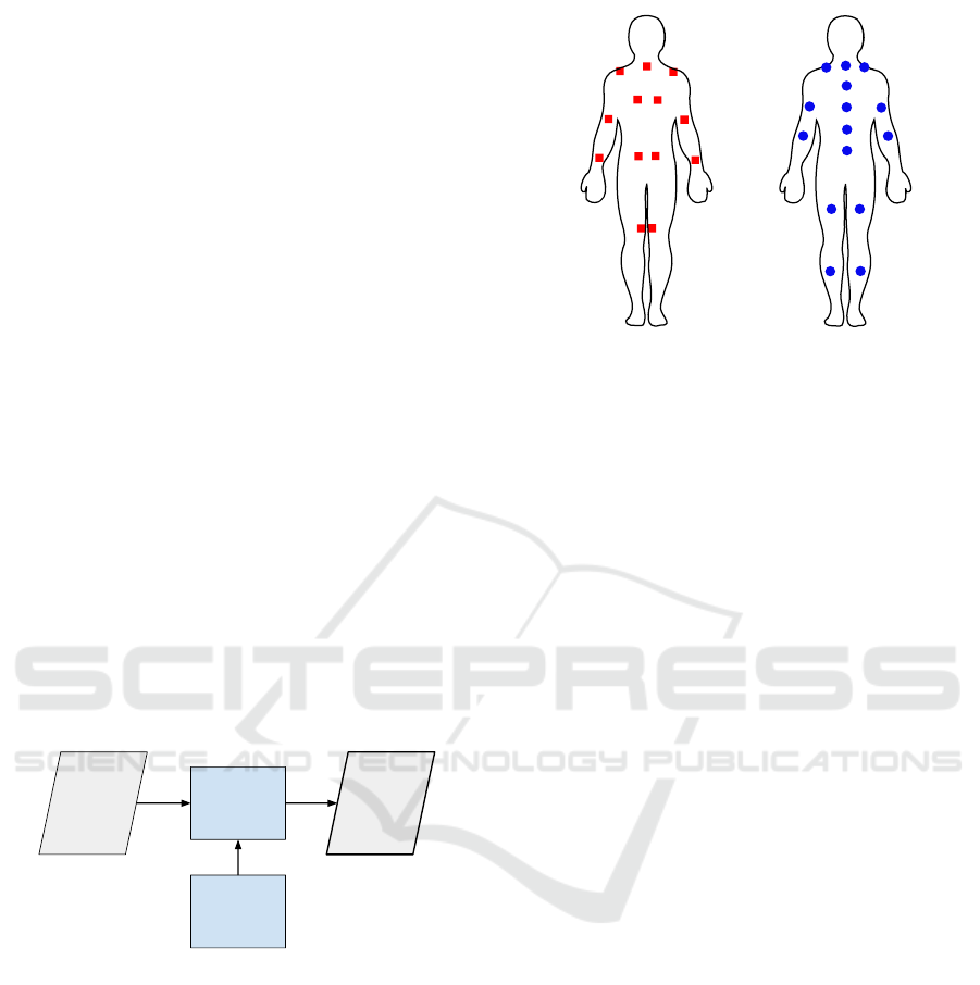
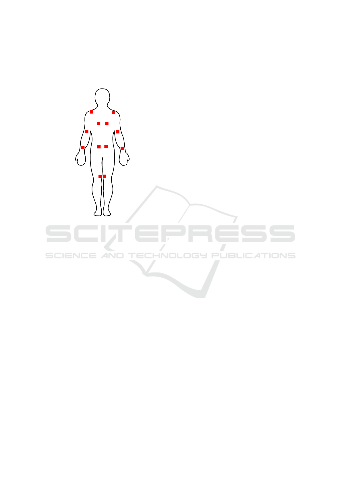
Figure 3: Placement of the tactors (red squares, left) and
motion sensors (blue circles, right) on the body (backview).
The system gets the skeletal motion capture data
from the suit’s sensor fusion component. At first,
the motion data is segmented into both movements
and static postures (Lins et al., 2018). The postures
are then risk rated using a predefined pose classifier,
e.g., based on common posture assessment methods,
in our case the Ovako Working Posture Analysis Sys-
tem (OWAS) (Karhu et al., 1977).
An improved version of the DSS as outlined in
Figure 2 may include a module that can - based on
the posture and the current work - guide the wearer to
a less awkward position through a custom vibrotactile
code. Spelzman et al. have developed such system for
snowboard training (Spelmezan et al., 2009).
3.3 Vibrotactile Interface
Our tactile display used in this work consists of 13
tactors placed next to joints and anatomic references
where the skin is relatively thin and location sensitive
(see Figure 3). The anatomical points for the tactor
placement are the neck, shoulders, elbows, wrists, the
lower end of shoulder blades, left and right of the lum-
bar spine, and on the inner side of the knees. Due
to the possibly higher perception of vibration near
bones, they might be used as a resonance body and
thus strengthen the perception of the vibration.
The vibration motor type used here is a rototac-
tor (type EKULIT VM 0610 A 3.0) that runs at a
fixed vibration frequency of 167 Hz, which is within
the optimal perception range (Jones and Sarter, 2008).
The vibration motors heads can rotate freely. There-
fore they are encased before their integration into the
workwear suit. For this reason, we 3D-printed fitting
plastic caps (see Figure 4 on the right) that cover the
spinning head and most of the motors. The caps are
fixed on the motors, so they are not vibrating within
the caps, but the head can spin freely.
ICT4AWE 2018 - 4th International Conference on Information and Communication Technologies for Ageing Well and e-Health
180
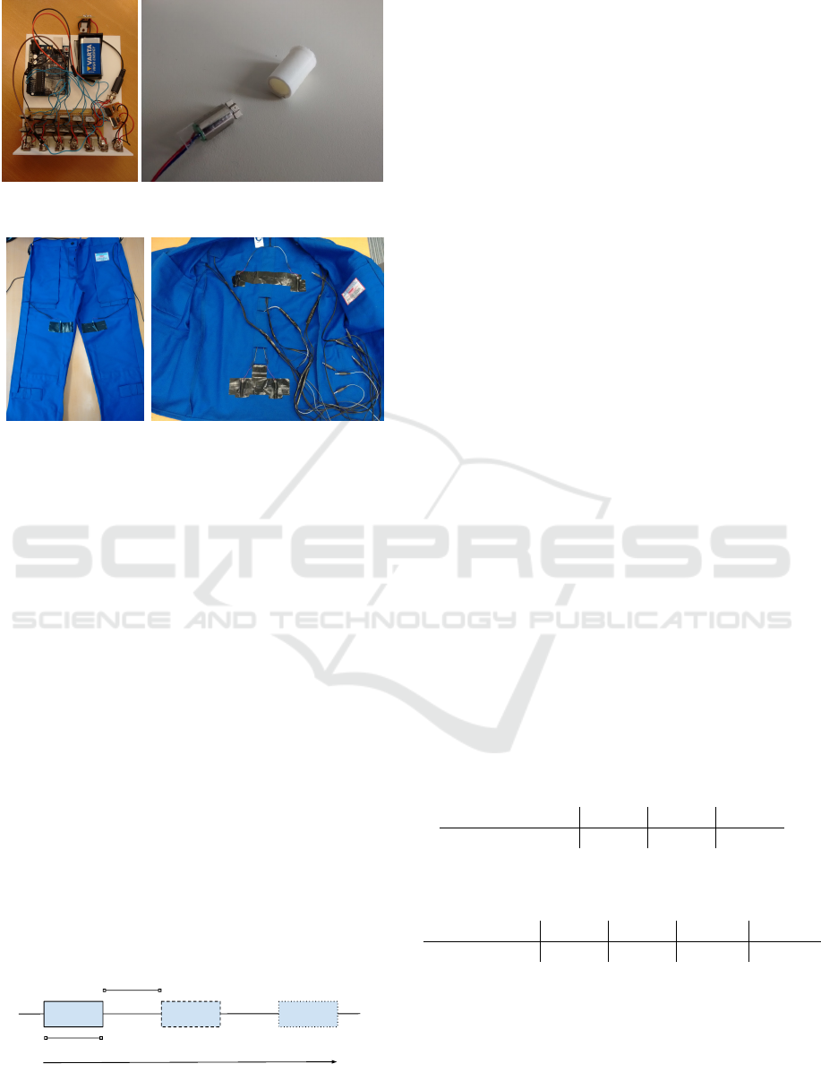
Figure 4: Opened prototype of the central unit (left) and a
vibration motor with its plastic cap (right).
Figure 5: Integration of the tactors into regular workwear.
The complete vibrotactile interface is integrated
into standard industrial workwear (rofa Beklei-
dungswerk) with cable canals and velcro closures for
the tactors. Some tactors are additionally fixed with
tape. Every tactor is connected to the central unit
(see Figure 4 on the left) using phone jack connectors.
Hence it is relatively easy to connect and disconnect
the central unit from the suit.
4 EVALUATION
The experiment aimed to determine the optimal range
of the following two vibration parameters to achieve a
high perceptional accuracy. These parameters are the
number of repetitions n of a single pulse P within a
warning sequence S as well as the optimum length p
t
of these individual pulses (see Figure 6). The pause
interval between pulse repetitions was chosen to be p
t
as well.
The experiments were carried out as part of a short
pilot study with a total of 11 subjects (8 male, 3 fe-
male).
1 2 3
p
t
p
t
Figure 6: A pulse sequence S consisting of one to three
pulses P each having length and pause interval p
t
.
4.1 Experimental Setup
Subjects were standing upright on two legs (OWAS
112) and had to determine the stimulating position.
Throughout the experiment, subjects had to point or
mention the limb (for example ”left shoulder”), which
were perceived as the most prominent source of vibra-
tion. The equality of the perceptions is also a valid an-
swer. The experimenter records the side on which the
subject perceived a stronger or more pronounced vi-
bration and the number of the tactor, which the subject
has perceived. The sequence of the VTI stimulation
positions is defined by a random repetitive vibrational
pattern (generated via pseudo-random number gener-
ator of the Arduino-based central unit) is used to max-
imizes the variance of the tested patterns and elimi-
nate potential biases due to the predictability of vibra-
tion location. To determine the optimal pulse length
and the optimal number of pulse repetitions per alarm
sequence, the central unit has been programmed such
that a random pair of pulses (e.g., knee left and knee
right) are recorded every 10 seconds with a random
pulse sequence. Pulse frequency and amplitude were
constant. The subject wore headphones listening to
pink noise to prevent them identifying the position
based on motor-sounds.
4.2 Results
In total we collected 539 evaluable left-right percep-
tions, each stated as SP = {S
L
, S
R
}, of 11 subjects.
Of these perceptions 306 samples were with a clearly
stronger left or right perception (S
L
> S
R
or S
R
> S
L
),
further called S
max
.
For all S
max
we summarized their number of repe-
titions and pulse lengths (see Table 1 and 2).
Table 1: The ratio of particular pulse sequence repetitions
within the strong perceptions, i.e. how many of the S
max
are
sequences with one, two or three repetitions.
Pulse repetitions 1 2 3
Ratio 22.9% 36.9% 40.2%
Table 2: The ratio of particular pulse lengths within the
strong perceptions, i.e. how many of S
max
are sequences
with pulse lengths of 25, 50, 100 or 150 milliseconds.
Pulse lengths 25 ms 50 ms 100 ms 150 ms
Ratio 12.7% 20.9% 27.8% 38.6%
These preliminary results show that a pulse se-
quence with two or three individual pulses, each with
a pulse length of 150 ms, is most clearly perceived.
This is also in line with the literature values, which
were tested directly on the skin (Van Erp, 2002).
However, the exact position of the vibration could
be localized correctly only in about 60.8% of the
A Wearable Vibrotactile Interface for Unfavorable Posture Awareness Warning
181
cases. The vibrations on the back were difficult to
perceive properly. In particular, the vibration motors
in the lumbar region were not perceived at all. The
reason for this is likely the loose jacket.
84.7%
65.9%
78.9%
74.1%
2.2%
56.4%
Figure 7: Percentage of correct localizations of the differ-
ent tactor groups (shoulders, upper arm, wrist, upper back,
lower back, knees). The values refer two both left and right
side.
Figure 7 shows the accuracy with which the vi-
brations at the individual body positions could be cor-
rectly localized.
5 DISCUSSION
In principle, a vibrotactile interface is suitable for un-
favorable posture warning. However, for the vibrotac-
tile interface, which has been tested here, the place-
ment of the tactors is not yet optimal (about 60% cor-
rect localization). As one can see, the perception is
good at the shoulders and wrists, slightly worse on
the arms and the upper back (see Figure 7). The lower
back tactor integrated into the jacket is not correctly
recognized in nearly every case. Sometimes the sub-
jects report undifferentiated vibrations somewhere on
the back. This is probably caused by the jacket that
is too loosely on the skin. A similar situation is at
the knees but not to this extent. So we can say the
vibrations, which were triggered by tactors close to
the skin, were perceptible in most cases. If the tactor
is only loosely on the skin due to folds or dampen-
ing effects of the fabric, the perception is significantly
worse. This issue is of great importance if the vibro-
tactile feedback should communicate postural change
hints to the wearer. If the VTI is not precise enough to
allow the wearer identify the limbs at risk, a change
hint will not be correctly perceived either.
In our pilot study, we have investigated the ef-
fect of varying the pulse lengths together with length-
adapted pause intervals between two pulses, i.e., p
t
=
pause. The follow-up study should investigate various
pause intervals as well.
Finally, it must be noted that further usability tests
are necessary, especially in combination with the pre-
viously untested connection to the decision support
system, i.e., to address the issue of alarm fatigue
(Wilken et al., 2017).
6 CONCLUSIONS AND FUTURE
WORK
We presented the concept and the first prototype of a
wearable vibrotactile interface (VTI) that is intended
for the usage in occupational environments to warn
its wearer of unfavorable or even dangerous postures.
The VTI can work in conjunction with IMU-based
sensor suits that can capture the motion and postures
of the user.
As a first step towards a closed-loop sensor and
feedback suit for preventing unfavorable postures at
work, we built a prototype of VTI and integrated
it into standard workwear. We conducted a pilot
study to identify the most strongly perceived vi-
bration parameters (length and repetition of pulse
codes). Additionally, we evaluated the location ac-
curacy of the perceived vibrations. We recommend
a pulse sequence of two 150 ms pulses for posture
warning. A third pulse would not increase the per-
ceptions much but cost additional energy. A pulse
length of 200 ms could improve the perception of an
alert, which should be verified in an additional study.
Longer pulses would probably irritate the users as
noted by Kaaresonja and Linjama (Kaaresoja and Lin-
jama, 2005).
Our findings indicate that the accuracy of such
VTI within the workwear vary substantially on the
body, so we propose changes for an improved version
of the VTI. First, the tactors of the lumbar back must
be integrated into the waistband of the suit’s trousers,
because the current placement on the jacket’s back has
proved itself practically useless (see 2.2% in Figure
7). Then, the number of tactors on the back can be re-
duced to minimize the complexity of the system in re-
gards to cabling. Finally, we will investigate the pos-
sibility to encode guidance information through vi-
brotactile codes (pulse lengths, repetitions, and varia-
tions in the pause interval), which guide users to better
ICT4AWE 2018 - 4th International Conference on Information and Communication Technologies for Ageing Well and e-Health
182

manual handling and avoidance of constrained pos-
tures.
ACKNOWLEDGMENTS
This work was partly funded by the German Ministry
for Education and Research (BMBF) within the joint
research projects SIRKA (grant 16SV6243). The au-
thors would like to thank all participants who par-
ticipated in the experiment. The photographs of
Figure 1 are used with courtesy of Meyer Werft
GmbH & Co. KG, Papenburg, Germany. This work
was additionally supported by the funding initiative
Nieders
¨
achsisches Vorab of the Volkswagen Founda-
tion and the Ministry of Science and Culture of Lower
Saxony as a part of the Interdisciplinary Research
Centre on Critical Systems Engineering for Socio-
Technical Systems II.
The authors would like to thank the anonymous
reviewers for their helpful comments.
REFERENCES
Alahakone, A. U. and Senanayake, S. M. N. A. (2010). A
real-time system with assistive feedback for postural
control in rehabilitation. IEEE/ASME Transactions on
Mechatronics, 15(2):226–233.
Amell, T. and Kumar, S. (2001). Work-related muscu-
loskeletal disorders: Design as a prevention strategy.
a review. Journal of Occupational Rehabilitation,
11(4):255–265.
Brell, M. and Hein, A. (2007). Positioning tasks in mul-
timodal computer-navigated surgery. IEEE MultiMe-
dia, 14(4):42–51.
Carvalho, P., Queir
´
os, S., Moreira, A., Brito, J. H., Veloso,
F., Terroso, M., Rodrigues, N. F., and Vilac¸a, J. L.
(2017). Instrumented vest for postural reeducation. In
5th International Conference on Serious Games and
Applications for Health. IEEE.
Gopalai, A. A. and Arosha Senanayake, S. M. N. A. (2011).
A wearable real-time intelligent posture corrective
system using vibrotactile feedback. IEEE/ASME
Transactions on Mechatronics, 16(5):827–834.
Hoy, D., Brooks, P., Blyth, F., and Buchbinder, R. (2010).
The epidemiology of low back pain. Best practice &
research Clinical rheumatology, 24(6):769–781.
Jones, L. A. and Sarter, N. B. (2008). Tactile displays:
Guidance for their design and application. Human
Factors, 50(1):90–111. PMID: 18354974.
Kaaresoja, T. and Linjama, J. (2005). Perception of short
tactile pulses generated by a vibration motor in a mo-
bile phone. In First Joint Eurohaptics Conference and
Symposium on Haptic Interfaces for Virtual Environ-
ment and Teleoperator Systems. World Haptics Con-
ference, pages 471–472.
Karhu, O., Kansi, P., and Kuorinka, I. (1977). Correcting
working postures in industry: A practical method for
analysis. Applied Ergonomics, 8(4):199–201.
Kerdegari, H., Kim, Y., and Prescott, T. J. (2016). Head-
mounted sensory augmentation device: Designing
a tactile language. IEEE Transactions on Haptics,
9(3):376–386.
Lederman, S. J. (1991). Skin and touch. Encyclopedia of
human biology, 7:51–63.
Lins, C., Eichelberg, M., R
¨
olker-Denker, L., and Hein,
A. (2015). SIRKA: Sensoranzug zur individu-
ellen R
¨
uckmeldung k
¨
orperlicher Aktivit
¨
at. In 55.
Wissenschaftliche Jahrestagung 2015 der Deutsche
Gesellschaft f
¨
ur Arbeitsmedizin und Umweltmedizin
e.V., M
¨
unchen, pages 301–303. Deutsche Gesellschaft
f
¨
ur Arbeitsmedizin und Umweltmedizin (DGAUM)
e.V.
Lins, C., M
¨
uller, S. M., Gerka, A., Pfingsthorn, M., Eichel-
berg, M., and Hein, A. (2018). Unsupervised temporal
segmentation of skeletal motion data using joint dis-
tance representation. In Proceedings of the 11th Inter-
national Joint Conference on Biomedical Engineering
Systems and Technologies (BIOSTEC/HEALTHINF
2018). SCITEPRESS Digital Library.
Matsui, H., Maeda, A., Tsuji, H., and Naruse, Y. (1997).
Risk indicators of low back pain among workers in
japan: association of familial and physical factors
with low back pain. Spine, 22(11):1242–1247.
Piateski, E. and Jones, L. (2005). Vibrotactile pattern recog-
nition on the arm and torso. In First Joint Eurohaptics
Conference and Symposium on Haptic Interfaces for
Virtual Environment and Teleoperator Systems. World
Haptics Conference, pages 90–95.
Punnett, L. and Wegman, D. H. (2004). Work-related mus-
culoskeletal disorders: the epidemiologic evidence
and the debate. Journal of Electromyography and Ki-
nesiology, 14(1):13 – 23. State of the art research
perspectives on muscoskeletal disorder causation and
control.
Spelmezan, D., Jacobs, M., Hilgers, A., and Borchers, J.
(2009). Tactile motion instructions for physical ac-
tivities. In Proceedings of the SIGCHI Conference
on Human Factors in Computing Systems, CHI ’09,
pages 2243–2252, New York, NY, USA. ACM.
Statistisches Bundesamt (2017). Krankheitskosten: Kosten
2015 nach Krankheitsklassen und Geschlecht in Euro
je Einwohner.
Van Erp, J. B. (2002). Guidelines for the use of vibro-tactile
displays in human computer interaction. In Proceed-
ings of eurohaptics, volume 2002, pages 18–22.
Walker, B., Muller, R., and Grant, W. (2003). Low back
pain in australian adults: the economic burden. Asia
Pacific Journal of Public Health, 15(2):79–87.
Wenk, F. and Frese, U. (2015). Posture from motion. In
2015 IEEE/RSJ International Conference on Intelli-
gent Robots and Systems (IROS), pages 280–285.
Wilken, M., H
¨
uske-Kraus, D., Klausen, A., Koch, C.,
Schlauch, W., and R
¨
ohrig, R. (2017). Alarm fatigue:
Causes and effects. Studies in health technology and
informatics, 243:107–111.
A Wearable Vibrotactile Interface for Unfavorable Posture Awareness Warning
183
