
Automatic Model Transformation from UML Sequence Diagrams to
Coloured Petri Nets
Jo
˜
ao Ant
´
onio Cust
´
odio Soares
1
, Bruno Lima
1,2
and Jo
˜
ao Pascoal Faria
1,2
1
Faculty of Engineering, University of Porto, Rua Dr. Roberto Frias, s/n, 4200-465 Porto, Portugal
2
INESC TEC, FEUP Campus, Rua Dr. Roberto Frias, s/n, 4200-465 Porto, Portugal
Keywords:
Model Transformation, Sequence Diagrams, Coloured Petri Nets, Epsilon, EMF.
Abstract:
UML Sequence Diagrams are used in different domains for specifying the required behaviour of software-
based systems. However, the created diagrams are often used only as documentation, and not as a basis for
generating subsequent lifecycle artifacts or for automated analysis. Several authors have proposed the transfor-
mation of Sequence Diagrams to executable Coloured Petri Nets (CPN), for simulation and testing purposes,
but the transformations are not automated or are implemented in an ad-hoc way. To overcome those limita-
tions, we present in this paper an approach to automatically translate Sequence Diagrams to CPN ready for
execution with CPN Tools, taking advantage of model-to-model transformation techniques provided by the
Eclipse Modelling Framework (EMF). The transformation rules are implemented in the Epsilon Transforma-
tion Language. We use the standard UML metamodel provided by EMF and the CPN metamodel provided by
CPN Tools, so any Sequence Diagram created with an EMF compliant modelling tool can be transformed. An
application example is presented to better illustrate the approach.
1 INTRODUCTION
UML Sequence Diagrams (SD) (UML, 2015) are
used in different domains for specifying the required
behaviour of software-based systems in an accessi-
ble notation. However, the created diagrams are of-
ten used only as documentation, and not as a basis for
generating subsequent lifecycle artifacts or for auto-
mated analysis. But since they are so easily designed
and understandable, and generally constructed in the
conception phase of the software project, there have
been many attempts to use them in an automated way
in later phases.
Coloured Petri Nets (CPN) (Jensen, 2013) are an
extension of basic Petri Nets (PN) (Murata, 1989), a
mathematical modelling formalism with well defined
execution semantics suitable for the description and
analysis of concurrent processes and distributed sys-
tems. A basic PN contains places and transitions con-
nected by arcs. In an execution state of a PN, also
called marking, each place holds zero or more tokens.
When a transition fires, it removes tokens from its in-
put places and adds tokens to its output places. CPN
allow for the definition of more complex nets with
typed (or coloured) places and tokens, guarded tran-
sitions, and arc expressions. The passing of tokens
through the firing of transitions represent the occur-
rence of an event and change of state in a system,
and can be executed step-by-step using tools like CPN
Tools, therefore, making them useful for simulation of
the behaviour of the modelled system.
Normally in the initial phases of a software de-
velopment project, SD would be produced to serve
as a basis for understanding and implementation of
use cases. On some projects, these use cases would
then be implemented and tested manually and the SD
wouldn’t be used again, as they provide no possi-
bility for automated processing. In Model-Driven-
Engineering (Schmidt, 2006), models take a central
role in the software development process. Model-to-
model and model-to-code transformations allow gen-
erating, directly or indirectly, subsequent lifecycle ar-
tifacts, such as executable models, source code, test
code, etc.
Several authors have proposed the transformation
of SD to CPN (Jensen et al., 2007), for simulation and
testing purposes, but the transformations are not au-
tomated, don’t take advantage of Model-Driven De-
velopment (MDD) techniques and technologies or
are implemented in an ad-hoc way (see Section 2),
strongly limiting re-use, extensibility and maintain-
ability.
668
Soares, J., Lima, B. and Faria, J.
Automatic Model Transformation from UML Sequence Diagrams to Coloured Petri Nets.
DOI: 10.5220/0006731806680679
In Proceedings of the 6th International Conference on Model-Driven Engineering and Software Development (MODELSWARD 2018), pages 668-679
ISBN: 978-989-758-283-7
Copyright © 2018 by SCITEPRESS – Science and Technology Publications, Lda. All r ights reserved
Hence, in this paper, we present an approach to
automatically translate SD, designed with a visual
modelling tool, to CPN ready for execution with
CPN Tools (Jensen et al., 2007), taking advantage of
model-to-model transformation techniques provided
by the Eclipse Modelling Framework (EMF) (Stein-
berg et al., 2008). The transformation rules were
implemented with the Epsilon Transformation Lan-
guage (ETL) (Kolovos et al., 2008). We use the stan-
dard UML metamodel provided by EMF and the CPN
metamodel provided by CPN Tools, so any SD cre-
ated with an EMF compliant modelling tool can be
transformed. We present an application example to
better illustrate the approach, as well as the imple-
mentation of these rules.
This article is structured as follows: Section 2 re-
lates this study with previous studies. Section 3 jus-
tifies the technology choices and gives an overview
of the architecture of the developed software mod-
ule. Section 4 presents the transformation rules that
were designed and implemented. Section 5 show-
cases the usage of the proposed model transformation
approach with an application example. Finally, Sec-
tion 6 presents some conclusions of the work done
and provides guidelines for future work.
2 RELATED WORK
The subject of applying model transformation from
UML SD to PN has been the subject of many pre-
vious studies. In (Bowles and Meedeniya, 2010)
the authors have proven with formal methods that the
model transformation rules approach allows a one-to-
one correspondence between the set of legal traces of
both models, that is, the languages are equivalent, also
known as strongly consistent. Although the trans-
formation rule based approach has been proven ad-
equate, the design of these transformation rules may
prove to be a challenge, given that SD have no for-
mal design rules. To surpass this complexity problem,
an example based heuristic search has been imple-
mented in (Kessentini et al., 2010) to produce results
with 96% correctness, although requiring a knowl-
edge base of many transformation examples with high
detail on the execution trace of the most complex frag-
ments. This transformation rule generation approach
would require the user to be experienced in CPN to
evaluate the results of the transformation, or a valida-
tion system to check conformity and consistency be-
tween the input and output model, therefore not being
adaptable to this software module’s requirements of
hiding complexity from the user.
The metamodel transformation approach was cho-
sen since it was proven feasible with formal methods
by (Ouardani et al., 2006) and the transformation
rules were derived from (Emadi and Shams, 2009)
and (Staines, 2013) that have conceptualized and val-
idated them for specific scenarios, although not im-
plementing them in an automated process. The rules
to produce the output CPN were extended from the
transformation rules proposed, alongside the toolkit
for conformance testing based on UML SD in (Faria
and Paiva, 2016). These studies were developed and
used as a base for designing transformation rules for
this type of model transformation for many applica-
tion domains and have been adapted and developed
in order to increase the value of SD. As proven in
(Jensen et al., 2007) CPN and CPN Tools can be used
for automatic validation of systems, either by creat-
ing animated system simulation to be used as vali-
dation with clients (Ribeiro and Fernandes, 2006)
and acceptance testing, or by generating automatic
test cases and execution scenarios (Lima and Faria,
2015), therefore justifying the need for this software
module.
3 OVERALL APPROACH AND
ARCHITECTURE
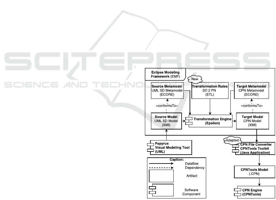
Figure 1: Dataflow view of the proposed model-to-model
transformation process.
Figure 1 presents a dataflow view of the proposed
model-to-model transformation process and of the
technologies used. The user only has to interact with
the visual modelling tool in order to create the input
SD; then the transformation process produces an ex-
Automatic Model Transformation from UML Sequence Diagrams to Coloured Petri Nets
669

ecutable CPN model that the user can execute with
CPN Tools (Jensen et al., 2007).
The visual modelling tool chosen was Pa-
pyrus (Lanusse et al., 2009), a visual modelling tool
integrated in EMF, that creates UML models in an
XMI like format which can be used as input in the
model-to-model transformation process. These mod-
els are validated to conform with the source meta-
model (UML metamodel encoded in the ECORE for-
mat (Sch
¨
atz, 2008)) provided by EMF, that define
rules for valid UML models.
The transformation rules were implemented us-
ing ETL, a state-of-the-art tool for model-to-model
transformation from Epsilon designed to pair with
EMF (Kolovos et al., 2006). These rules are designed
to map elements from the source metamodel to ele-
ments of the target metamodel, a metamodel for CPN
that supports the required features by CPN Tools to
create an executable model. These transformation
rules are then applied to an UML SD and create an
equivalent model of a CPN. Equivalent models, in this
case, are CPN that accept the same execution traces
(event sequences) as the original SD.
The generated CPN models are also in the EMF
default format (XMI), and therefore need to be con-
verted into the CPN Tools format (.cpn) to success-
fully accomplish the goal of this solution. For that
reason, a CPN File Converter was designed as a Java
Application Plug-in, using an open-source Plug-in
(CPN Tools Toolkit (G
´
omez, 2016)) that provides an
API to serialize XMI files into the CPN Tools format.
Finally, this file converter is applied to the model orig-
inated from the Epsilon transformation rules and cre-
ates a file containing an executable CPN that can be
used with CPN Tools.
With this process we can hide from the user the
complexity of designing valid executable CPN by au-
tomatically generating them from UML SD. There-
fore, by joining the simplicity to design and interpre-
tation of SD with the possibility of automated pro-
cesses of CPN, an increase in productivity in the soft-
ware development process can be achieved.
4 TRANSFORMATION RULES
The transformation process is based on metamodels,
therefore, the transformation rules (TRs) are designed
to iterate through the input model’s elements and then
add the equivalent elements to an initially empty out-
put model. The rules are applied sequentially to every
element of the input model which type matches the
rule’s target type, incrementally building the result.
If TRs exist mapping every type of element from the
rule sequenceDiagram2colouredPetriNets
transform m1 : SD!Message
to p1: PN!Place, t1: PN!Trans
{
pn.addPlace(p1,m1.name);
pn.addTransition(t1,"Send" + m1.name);
pn.addArcPT(p1,t1,"n");
}
Figure 2: Example of ETL transformation rule.
input meta model to equivalent elements of the out-
put meta model, in a way that is scalable for the rules
to interoperate, after every rule is executed, the result
should model the same behaviour as the original, but
in a different notation.
The visual modelling tool performs systematic
checking on the input model’s elements, so validation
of the input model is not required.
The core and most useful UML SD features for
modelling the behaviour of distributed systems were
chosen to be implemented, to allow the application of
this solution for the integration testing of distributed
systems (Lima and Faria, 2015). The core features are
lifelines and asynchronous messages as these are the
basis of the communication process in distributed sys-
tems, and the most useful components are combined
fragments as these allow to introduce complexity and
shape the logical structure of the execution.
The TRs enumerated in Table 1 are interdepen-
dent, as some rules depend on the results of other rules
being previously applied. Therefore, executing each
of them sequentially in a determined order respecting
these inter-dependencies will incrementally build the
desired result. This rule precedence guarantees con-
sistency between the order of events in the input and
the output model, and is shown by the last column of
Table 1.
Figure 2 shows a sample of code of an ETL
TR for explanatory purposes. This rule ”sequence-
Diagram2colouredPetriNets” targets each element of
type Message from the SD meta model ”m1” present
in the input model and generates two elements: ”p1”
of type Place from the CPN meta model and ”t1” of
type Transition from the CPN meta model. This rule’s
body then adds the generated elements to the output
model ”pn” using the message’s name, and creates a
connecting arc between them.
The following subsections will describe the im-
plementation of these TRs. Each of the rule’s purpose
will be first presented, then the process will be ex-
plained step-by-step, using a diagram to support this
explanation if necessary, then, finally, it’s purpose is
justified.
These step-by-step explanations follow a notation
of abbreviations so that it’s more concise and easy to
AMARETTO 2018 - Special Session on domAin specific Model-based AppRoaches to vErificaTion and validaTiOn
670
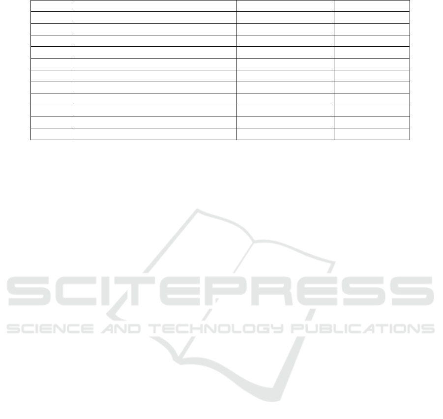
Table 1: Transformation rule set.
Rule ID Name Transformed Element Preceding Rules
R1 Initial transformation SD -
R2 Lifelines to initial places Lifeline R1
R3 Events to after places MessageOccurrence R1
R4 Weak sequencing combined fragments CombinedFragment R2,R3
R5 Strict sequencing combined fragments CombinedFragment R2,R3
R6 Parallel combined fragments CombinedFragment R2,R3
R7 Alternative combined fragments CombinedFragment R2,R3
R8 Optional combined fragments CombinedFragment R2,R3
R9 Loop combined fragments CombinedFragment R2,R3
R10 Transformation of messages Message R4,...,R9
R11 Final Transformation SD R10
understand. This notation is as follows:
• ”B” represents ”begin”;
• ”E” represents ”end”;
• ”A” represents ”after”;
• ”Y” represents ”yes”;
• ”N” represents ”no”;
• ”S” represents ”send”;
• ”R” represents ”receive”;
• ”T” represents the type of combined fragment
(operator);
• ”F” represents the id of the combined fragment;
• ”O” represents the id of the ”InteractionOperand”
of a combined fragment;
• ”L” represents the id of a Lifeline;
• ”M” represents the id of a Message.
4.1 Initial Transformation
The first TR (R1) is executed only once and before
all others, therefore it was implemented as an ETL
”pre” function that has no target elements in the in-
put model. The purpose of this TR is to initialize the
output model and create the initial state of the mod-
elled system. It generates the following elements on
the output CPN:
1. ”B” Place with initial marking of the net;
2. ”Start” Transition;
3. Arc from ”B” to ”Start”.
The marking of the net is introduced as a simple
token of colour type ”INT” with value 1. Since there
still isn’t a need to introduce complexity on the token
system, all generated places will be associated with
tokens of this type. A variable ”n” of type ”INT”
is also created to be used as a constraint in the con-
necting arcs, so that the initial token created can be
consumed and transmitted throughout the transitions.
These generated elements are then stored as global
variables so that they can be accessed from other rules
in order to complete the net. This TR is also responsi-
ble for generating the Graphical User Interface (GUI)
elements necessary for it to be executable in CPN
Tools, such as the Page element (graphical container
for the net), the Declarations block (container for vari-
ables and colour sets) and the basic token to be used
as the initial marking of the net.
4.2 Lifelines to Initial Places
The second transformation rule (R2) applies to input
elements of type ”Lifeline”. The purpose of this TR
is to create the initial state for each of the lifelines
in the system. This transformation rule is dependent
on R1 and therefore must be executed after it. For
each lifeline, it generates the following elements on
the output CPN:
1. ”BL” Place;
2. Arc from ”Start” to ”BL”.
When the ”Start” transition is fired, the token from
the initial marking will be transmitted into each of
these places, enabling the firing of subsequent tran-
sitions, modelling the behaviour of the system.
4.3 Events to After Places
The third transformation rule (R3) targets input el-
ements of type ”MessageOccurrenceSpecification”.
These elements represent events in a lifeline of ei-
ther sending or receiving a message. The purpose of
this TR is to create the places representing the state
in which the lifeline will be after executing that ac-
tion. For each pair of event occurrences it generates
the following elements on the output CPN:
1. ”ASML” Place for each message sent;
Automatic Model Transformation from UML Sequence Diagrams to Coloured Petri Nets
671
2. ”ARML” Place for each message received.
In the UML meta model, each SD element of
type ”Message” is connected to two elements of type
”MessageOccurrenceSpecification”, one representing
the ”Send” event and the other the ”Receiving” event.
Each lifeline holds the events connected to itself in an
ordered container. The top most occurrence will be
the first to be translated and the bottom one will be
the last. This TR is not dependent on any other so it
may be executed after R1, and, alongside the places
generated in R2, it creates the structure where after-
wards the more complex elements will be connected
to, guaranteeing the correct order of event execution.
4.4 Weak Sequencing Combined
Fragments
Combined fragments are composed of two core ele-
ments: ”InteractionOperator” and a set of ”Interac-
tionOperands”. Each operand represents a ”frame”
within the combined fragment and contains the events
that occur in that frame in an ordered container. Each
”frame” represents an independent interaction and
can itself hold other combined fragments. The opera-
tor is a property that defines the type of the combined
fragment. By determining the type of the combined
fragment, different rules may be applied.
The fourth transformation rule (R4) targets weak
sequencing combined fragments, defined by the oper-
ator ”seq”. The purpose of this rule is to create a struc-
ture in the output model that enforces a behaviour that
each lifeline will only progress to another ”Interac-
tionOperand” when it concludes the current operand’s
execution. It generates the following elements on the
output CPN:
1. For each ”Lifeline” present in the combined frag-
ment:
(a) ”BTFOL” Transition;
(b) Arc from the previous place in the lifeline to
”BTFOL”;
(c) For each ”InteractionOperand”:
i. ”AFOL” Place;
ii. ”EFOL” Transition;
iii. Arc from the last ”After” place of the operand
to ”EFOL”;
iv. Arc from ”BTFOL” or from the last operand’s
”EFOL” to ”AFOL”;
(d) ”ATFL” Place;
(e) Arc from the last ”EFOL” to ”ATFL”.
This TR’s execution is dependent on places gener-
ated by the translation of the events in R3 and the ini-
tial places for each lifeline generated in R2, therefore,
must be executed after these TRs. If the last event of
an operand is a combined fragment that has not been
translated at the point of execution, the ”After” place
for that combined fragment is generated and used, and
will not be created during the translation of that com-
bined fragment. This occurs in the translation of every
combined fragment (R4,R5,R6,R7,R8,R9).
Figure 3: CPN pattern for translating weak sequencing
combined fragments.
Figure 3 represents the CPN pattern that results
from the translation of weak sequencing combined
fragments. Circles correspond to places in the out-
put model CPN, while rectangles correspond to tran-
sitions. The elements with full lines represent the
CPN elements that are generated from translating a
UML SD with two lifelines and one operand, while
the elements in dashed lines represent elements that
would already exist in the output model at this point
in execution. Each of the vertical structures represents
a lifeline. The top most places represent the places in
the output model that correspond to the previous place
for each lifeline. The second pair of dashed lined
places represent the places corresponding to the last
events for the first operand.
4.5 Strict Sequencing Combined
Fragments
The fifth transformation rule (R5) targets strict se-
quencing combined fragments, defined by the oper-
ator ”strict”. The purpose of this rule is to create
a structure in the output model that enforces a be-
haviour that each lifeline will only progress to an-
other ”InteractionOperand” when all other lifelines
in the combined fragment conclude executing that
operand. It generates the following elements on the
output CPN:
AMARETTO 2018 - Special Session on domAin specific Model-based AppRoaches to vErificaTion and validaTiOn
672
1. For each ”Lifeline” present in the combined frag-
ment:
(a) ”BTFO” Transition;
(b) Arc from previous place in the lifeline to
”BTFO”;
(c) For each ”InteractionOperand”:
i. ”AFOL” Place;
ii. ”ETFO” Transition;
iii. Arc from the last ”After” place of the operand
to ”ETFO”;
iv. Arc from this operand’s ”BTFO” to ”AFOL”;
(d) ”ATFL” Place;
(e) Arc from the last ”ETFO” to ”ATFL”.
The final transition of each operand can only be
fired when all lifelines reach their final place for that
operand, therefore, guaranteeing the strict sequenc-
ing of events. This TR’s execution is dependent on
places generated by the translation of the events in R3
and the initial places for each lifeline generated in R2,
therefore, must be executed after these TRs.
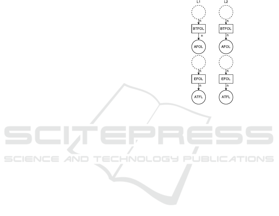
Figure 4: CPN pattern for translating strict sequencing com-
bined fragments.
Figure 4 represents the CPN pattern that results
from the translation of strict sequencing combined
fragments. The elements with full lines represent the
CPN elements that are generated from translating a
UML SD with two lifelines and one operand, while
the elements in dashed lines represent elements that
would already exist in the output model at this point
in execution. By connecting the previous place of
each lifeline involved in the combined fragment to the
same starting transition, and every last place of each
lifeline to the same final transition for each operand,
these transitions can only be fired upon every lifeline
reaching the operand’s final place, therefore, enforc-
ing the strict sequencing behaviour.
4.6 Parallel Combined Fragments
The sixth transformation rule (R6) targets parallel
combined fragments, defined by the operator ”par”.
The purpose of this rule is to create a structure in the
output model that enforces a behaviour that allows for
each lifeline to execute multiple operands simultane-
ously. It generates the following elements on the out-
put CPN:
1. For each ”Lifeline” present in the combined frag-
ment:
(a) ”BTFL” Transition;
(b) Arc from previous place in the lifeline to
”BTFL”;
(c) ”ETFL” Transition;
(d) For each ”InteractionOperand”:
i. ”AFOL” Place;
ii. Arc from the last ”After” place of the operand
to ”ETFL”;
iii. Arc from ”BTFL” to ”AFOL”;
(e) ”ATFL” Place;
(f) Arc from ”ETFL” to ”ATFL”.
The final transition of each lifeline can only be
fired when the execution of all operands reaches its
final place, therefore, guaranteeing the parallel exe-
cution of events. This TR’s execution is dependent on
places generated by the translation of the events in R3
and the initial places for each lifeline generated in R2,
therefore, must be executed after these TRs.
Figure 5: CPN pattern for translating parallel combined
fragments.
Figure 5 represents the CPN pattern that results
from the translation of parallel combined fragments.
Automatic Model Transformation from UML Sequence Diagrams to Coloured Petri Nets
673
The elements with full lines represent the CPN ele-
ments that are generated from translating a UML SD
with two lifelines and two operands, while the ele-
ments in dashed lines represent elements that would
already exist in the output model at this point in ex-
ecution. The top most transition is ”BeginPar” and
connects to the initial place of each operand. When
it’s fired, it transmits its incoming tokens to multiple
places, therefore, granting the concurrent execution
behaviour to the CPN.
4.7 Alternative Combined Fragments
The seventh transformation rule (R7) targets alter-
native combined fragments, defined by the operator
”alt”. The purpose of this rule is to create a structure
in the output model that enforces a behaviour that al-
lows for one of the lifelines to take the decision of
which, if any, of the operands to execute. This deci-
sion will be made by the ”Deciding Lifeline” that is
determined by which lifeline executes the first event
(sends the first message) in the operand. It generates
the following elements on the output CPN:
1. For each Lifeline:
(a) Transition ”NTFL” to represent a negative de-
cision;
(b) Transition ”YTFOL” for each operand in the
combined fragment;
(c) Arc from previous place in the lifeline to
”NTFL” and every ”YTFOL”;
(d) ”ATFL” Place;
(e) ”decider” Place to serve as an intermediate
place to propagate the deciding lifeline’s deci-
sion;
(f) If it is the ”DecidingLifeline”:
i. Arc from ”NTFL” to ”decider” with inscrip-
tion ”0”;
ii. Arc from every ”YTFOL” to ”decider” with a
unique integer inscription;
(g) If it is not:
i. Arc from ”decider” to each of the operands’
”YTFOL” with a unique integer inscription;
ii. Arc from ”decider” to ”NTFL” with inscrip-
tion ”0”;
(h) Arc from ”NTFL” to ”ATFL”;
(i) For each Operand:
i. ”AFOL” Place;
ii. Arc from that operand’s ”YTFOL” to
”AFOL”;
iii. ”EFOL” Transition;
iv. Arc from the last ”After” place of the operand
to ”EFOL”;
v. Arc connecting ”EFOL” to ”ATFL”.
This way a structure is created for alternative ex-
ecution behaviour that conforms to the UML specifi-
cation, since only one of the decisions can be taken
and is made by one of the lifelines. By passing to
”decider” a token of unique value for each decision
made by the deciding lifeline, it ensures that the other
lifelines may only take the same decision as the de-
ciding lifeline. This TR’s execution is dependent on
places generated by the translation of the events in R3
and the initial places for each lifeline generated in R2,
therefore, must be executed after these TRs.
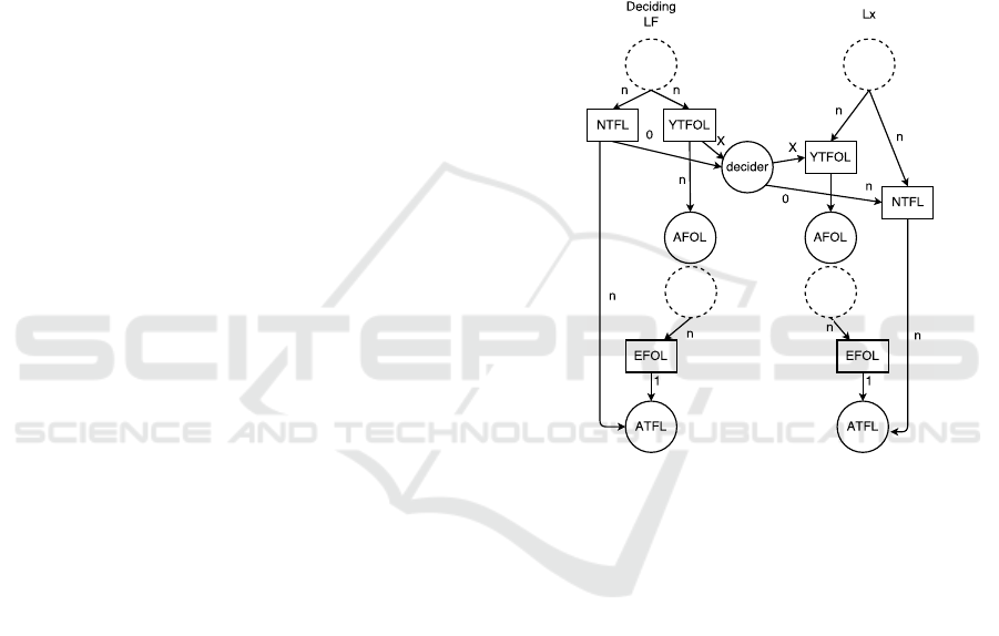
Figure 6: CPN pattern for translating alternative combined
fragments.
Figure 6 represents the CPN pattern that results
from the translation of alternative combined frag-
ments. The elements with full lines represent the CPN
elements that are generated from translating a UML
SD with two lifelines and two operands, while the el-
ements in dashed lines represent elements that would
already exist in the output model at this point in exe-
cution. In this case, the Deciding Lifeline is the left
vertical structure. The value ”X” on the arcs repre-
sents the unique integer assigned to the operand, and
the output model will have as many of these transi-
tions connected to ”decider” as operands present in
the combined fragment, each of them representing a
possible choice to be made by the deciding lifeline.
4.8 Optional Combined Fragments
The eighth transformation rule (R8) targets optional
combined fragments, defined by the operator ”opt”.
The purpose of this rule is to create a structure in the
AMARETTO 2018 - Special Session on domAin specific Model-based AppRoaches to vErificaTion and validaTiOn
674
output model that enforces a behaviour that allows for
one of the lifelines to take the decision of whether or
not to execute the interaction operand.
Optional combined fragments are translated as
a simplification of Alternative combined fragments,
since optional combined fragments are just alterna-
tive combined fragments with only one operand and
only one decision to take (”Yes” or ”No”).
4.9 Loop Combined Fragments
The ninth transformation rule (R9) targets loop com-
bined fragments, defined by the operator ”loop”. The
purpose of this rule is to create a structure in the
output model that enforces a behaviour that allows
for one of the lifelines to decide how many times an
operand will be executed, according to the values ”n”
and ”m” for minimum and maximum amount of it-
erations, that serves as a constraint for the combined
fragment. This decision will be made by the ”Decid-
ing Lifeline” that is determined by which lifeline ex-
ecutes the first event (sends the first message) in the
operand. It generates the following elements on the
output CPN:
1. A variable ”c” of type ”INT” is created to be used
as a counter for the loop;
2. For each Lifeline:
(a) Transitions ”YTFL” and ”NTFL” to represent
affirmative and negative decisions for each life-
line;
(b) ”decider” Place to serve as an intermediate
place to propagate the deciding lifeline’s deci-
sion;
(c) Arc from previous place in the lifeline to
”NTFL” and ”YTFOL”;
(d) ”AFOL” Place;
(e) Arc from ”YTFL” to ”AFOL”;
(f) ”CTFL” Transition with a transition constraint
”c ≤ M”;
(g) ”ETFL” Transition with a transition constraint
”c ≥ N”;
(h) ”ATFL” Place;
(i) Arc from ”ETFL” to ”ATFL”;
(j) Arc from the last ”After” place of the operand
to ”ETFL” and ”CTFL”;
(k) If it is the deciding lifeline:
i. Arcs from ”YTFL” and ”NTFL” to ”decider”
with inscriptions ”1” and ”0” respectively;
ii. ”counter” Place;
iii. Arc from ”YTFL” to ”counter” with inscrip-
tion ”1” to initialize the counter;
iv. Arc from ”CTFL” to ”counter” with inscrip-
tion ”c+1”;
v. Arcs from ”counter” to ”ETFL” and ”CTFL”
with inscription ”c”;
(l) If it is not the deciding lifeline:
i. Arcs from ”decider” to ”YTFL” and ”NTFL”
with inscriptions ”1” and ”0” respectively;
ii. ”prop” Place to propagate the decision of re-
peating the operand or not;
iii. Arcs from the deciding lifeline’s ”CTFL” and
”ETFL” transition to ”prop” with inscriptions
”1” and ”0” respectively;
iv. Arcs from ”prop” to ”CTFL” and ”ETFL”
with inscriptions ”1” and ”0” respectively;
(m) Arc from ”CTFL” to ”AFOL”.
This way a structure is created for loop execution
behaviour that conforms to the UML specification,
controlled by the deciding lifeline that ultimately de-
cides the number of iterations to be used by all other
lifelines. This TR’s execution is dependent on places
generated by the translation of the events in R3 and
the initial places for each lifeline generated in R2,
therefore, must be executed after these TRs.
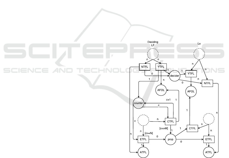
Figure 7: CPN pattern for translating loop combined frag-
ments.
Figure 7 represents the CPN pattern that results
from the translation of loop combined fragments. The
elements with full lines represent the CPN elements
that are generated from translating a UML SD with
two lifelines and two operands, while the elements
in dashed lines represent elements that would already
Automatic Model Transformation from UML Sequence Diagrams to Coloured Petri Nets
675
exist in the output model at this point in execution.
In this case, the Deciding Lifeline is the left vertical
structure, so it’s different from the one on the right
as it has the iteration counter system. The ”CTFL”
transition is connected to the ”AFOL” to allow for the
looping behaviour.
4.10 Transformation of Messages
The tenth transformation rule (R10) targets input el-
ements of type ”Message”. These elements represent
asynchronous messages that are passed between the
lifelines of the system making up the system’s com-
munication. The purpose of this TR to use the previ-
ously generated elements of the output model to place
the passing of messages in the correct order of exe-
cution. For each message it generates the following
elements on the output CPN:
1. ”SML” Transition;
2. ”RML” Transition;
3. ”M” Place to represent the message in transit;
4. Arc from previous place in the lifeline to ”SML”
and ”RML” accordingly;
5. Arcs from ”SML” to ”M” and ”M” to ”RML”;
6. Arcs connecting ”SML” and ”RML” to the re-
spective ”ASML”/”ARML” place.
The matching of places will be made by compar-
ing the places’ ids with the message to be translated,
so the messages will be placed in the correct part of
the output model. This TR’s execution is dependent
on places generated by the translation of the events in
R3, the initial places for each lifeline generated in R2
and by the structures generated by R4,R5,R6,R7,R8
and R9, therefore, must be executed after these TRs.
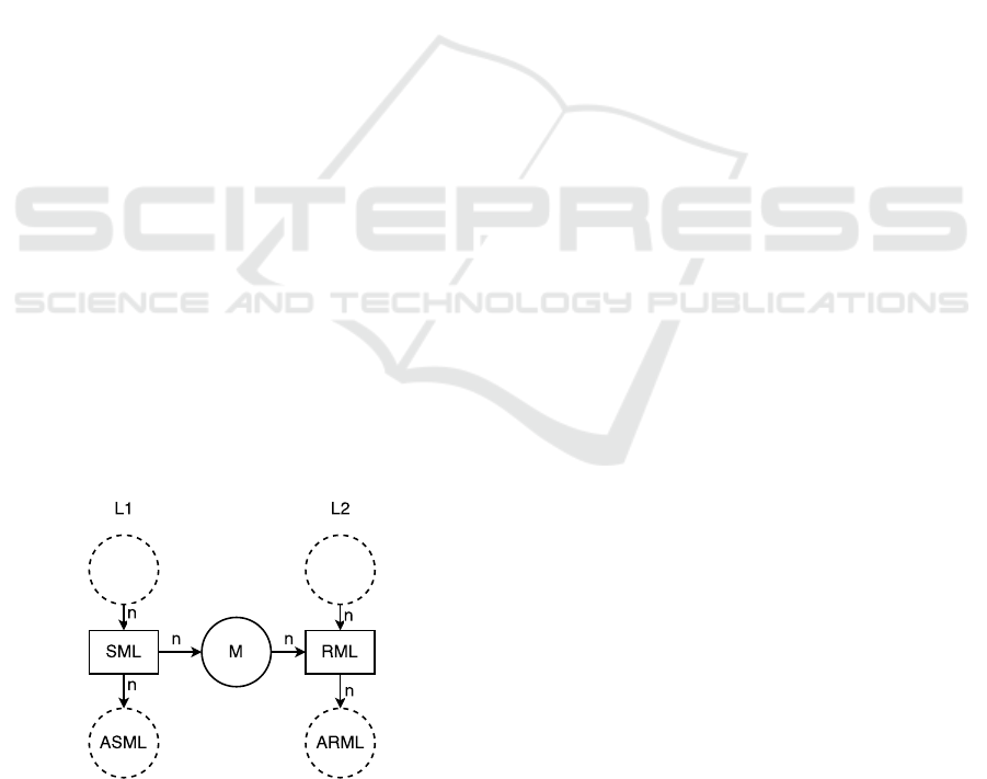
Figure 8: CPN pattern for translating asynchronous mes-
sages.
Figure 8 represents the CPN pattern that results
from the translation of messages. The elements with
full lines represent the CPN elements that are gener-
ated from translating a message being passed between
two lifelines, while the elements in dashed lines rep-
resent elements that would already exist in the output
model at this point in execution. The left transition
represents the sending of the message, the place in
the middle represent the state of the system in which
the message is in traffic, while the right transition rep-
resents the message being received.
4.11 Final Transformation
The last TR (R11) is executed only once and after
all others, therefore it was implemented as an ETL
”post” function that has no target elements in the in-
put model. The purpose of this TR is to create the
place corresponding to the final state of the system,
and connect it correctly to the previously generated
elements of the output model. It generates the follow-
ing elements on the output CPN:
1. ”E” Transition;
2. ”Final” Place;
3. Arcs from the unconnected places to ”E”;
Because of the way the transformation rules were
designed, there will only be one unconnected place in
the output model for each lifeline in the source model.
With this we successfully create an equivalent CPN
to the initial SD, that is interpretable by CPN Tools
and executable, but that is not ready for execution yet.
This is due to the output model being represented in a
format that is not recognizable by the tool and, there-
fore, must be transformed by the developed CPN File
Converter.
5 APPLICATION EXAMPLE
In this section we present an example application of
the previously described transformation process and
rules.
The input SD is a simple SD shown in Figure 9.
It contains three asynchronous messages that are ex-
changed between the three different lifelines within a
system. The result of the transformation process for
this SD is shown in Figure 10 along some visual an-
notations added for explanatory purposes.
Before execution of the transformation, the input
model is validated for conformance with the source
metamodel by the Papyrus visual modelling tool. The
transformation process will then apply each transfor-
mation rule iteratively to the input model in order to
create an equivalent target model.
AMARETTO 2018 - Special Session on domAin specific Model-based AppRoaches to vErificaTion and validaTiOn
676
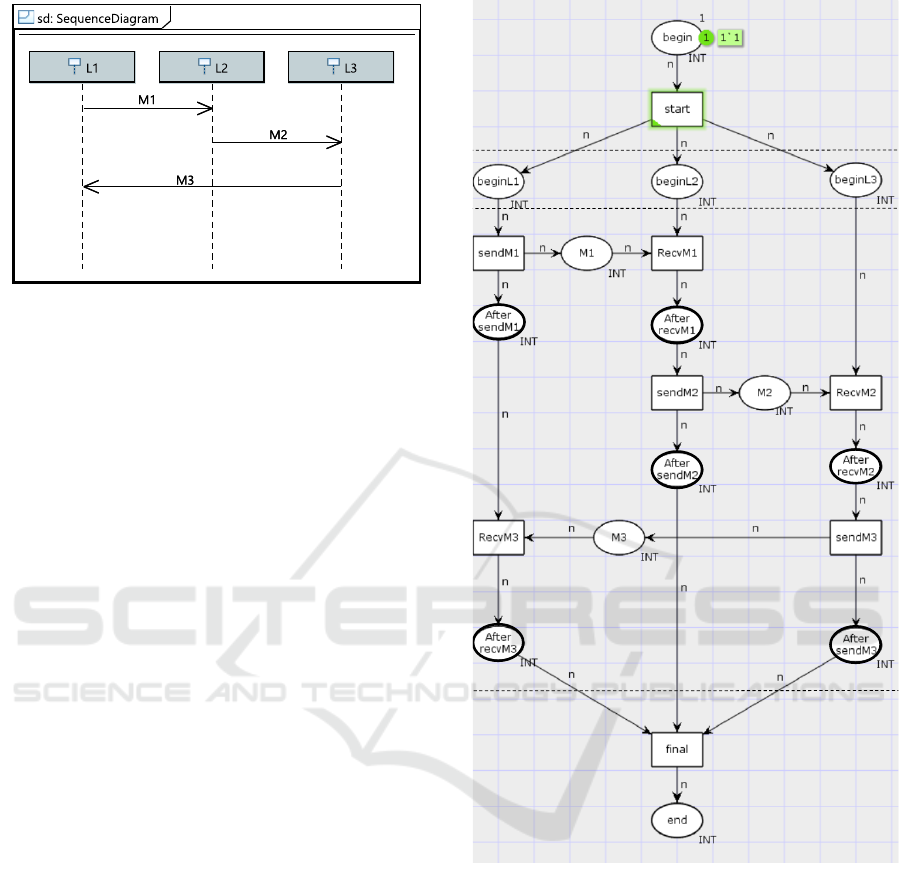
Figure 9: Simple UML Sequence Diagram (created with
Papyrus).
The first rule’s objective is to initialize the key
components for the target model to be executable in
CPN Tools, and create the initial states of the target
model. The first elements to be declared are the object
for the output model, the ”Page” to hold the model,
the ”INT” colourset and the ”n” variable to be used
as a generic inscription for arcs. These are inserted
in the ”Declaration” block of the ”Page” containing
the output model in order for the generated CPN to be
executable. The core elements (initial place/transition
pair) are then declared and added to the output model,
and the system’s initial marking is defined, as shown
as the top region in Figure 10. The output model is
now ready to be completed with more elements.
The order of progress will now be to apply each
rule to every matching element in the input model.
The next step will then be to create the places corre-
sponding to the initial states for each lifeline. Since
the example input model has three lifelines (”L1”,
”L2” and ”L3”), three places will be added to the out-
put model (”BeginL1”, ”BeginL2” and ”BeginL3” re-
spectively). These places will then be connected to an
arc originating from the initial transition, as shown in
the second region counting from the top in Figure 10.
The next rule to be applied will generate the ”Af-
ter” place for each event. These places, alongside the
places already added to the output model, will not
be connected to each other just yet, as this will oc-
cur as the events are being translated in further steps
of the transformation process. Since the example in-
put model has three messages being passed, and each
message has two events associated to it (sending and
receiving the message), six places will be generated
in this step, as shown by the highlighted places (bold
contours) in the middle region of Figure 10. The re-
sult at this point of the transformation process is the
core structure of the target model, as the actions and
interactions will later be translated, matched and con-
R1
R2
R3
+
R4
R5
Figure 10: Output model in CPN Tools with annotations.
nected to this structure.
The next step is to translate the interaction be-
tween lifelines, as there are no combined fragments
in this example. Since each message is going to have
a sending and receiving event, a transition for each of
these events will be generated, and these will later on
represent steps in execution when they are fired. The
message translating rule will iterate through the exist-
ing messages, and match the transitions with the ”Af-
ter” places associated with the events of sending and
receiving that message with a connecting arc. Since
the events are in an ordered container in the lifeline
they are associated with, the events associated with
the message can be used to retrieve the previous event
Automatic Model Transformation from UML Sequence Diagrams to Coloured Petri Nets
677

in that lifeline in order to match them with the corre-
sponding place in the output model, successfully plac-
ing the message passing pattern in the target model
structure resulting from the previous rules. When an
event has no previous events in the lifeline, the tran-
sition is matched to the initial ”Begin” place of that
lifeline. The transitions are then connected with an
intermediate place representing the message in traf-
fic state, as shown by places ”M1”, ”M2” and ”M3”
in the middle region of Figure 10, leaving only the
place representing the final state of each lifeline un-
connected.
Finally, in order to complete the output model, the
last rule is applied. Because of the design of the trans-
formation rules, and the Place matching made using
the event’s id, no valid SD using only the supported
features for this software module will create an output
model with more than one place for the final state of
each lifeline. This implies that, for each lifeline, only
one arc will be generated connecting its final place to
the final transition, and therefore, for the example in-
put model, three arcs will be created, as shown in the
bottom region of Figure 10.
The model-to-model transformation component
of the transformation process is complete, and the out-
put model is encoded in a file of XMI format specific
to EMF. In order for this model to be used externally
by CPN Tools, this file must be converted to the spe-
cific tool format (.cpn). The CPN File converter cre-
ated is used for this purpose, as it uses an existing
plug-in for the serialization of files from EMF into
CPN Tools specific files, as long as they conform with
the metamodel used by the tool.
The generated CPN file (.cpn) can now be exe-
cuted by the user step by step with CPN Tools. This
type of behaviour in a model can be valuable as the
transitions can be fired from an external program via
an API for CPN Tools and therefore introduce the
possibility for automatic processes to analyze a sys-
tem’s execution from an otherwise ”static” SD, and
possibly generate code or perform automated proce-
dures.
We have applied the approach for more complex
SD, with several types of combined fragments, but
omit them here because of the size and the complexity
of the generated CPN. (Soares, 2017)
6 CONCLUSIONS AND FUTURE
WORK
We presented an automated model-to-model transfor-
mation approach from UML SD to CPN. Our ap-
proach was successfully implemented based on state-
of-the-art model-transformation techniques and tools,
namely EMF and ETL, and an experiment was con-
ducted to validate and illustrate the approach. To our
knowledge, there is no other previous approach able
to automatically perform the end-to-end transforma-
tion, from SD created with a visual modelling tool to
CPN executable with CPN Tools, without any manual
step. ETL allowed us to define the transformations in
a declarative and extensible way.
As future work we intended to implement the re-
maining features of UML SD such as: synchronous
messages, action/behaviour specification, break com-
bined fragments, negative combined fragments, crit-
ical combined fragments, ignore combine fragment,
consider combined fragments and assertion combined
fragments. These will be implemented as ETL trans-
formation rules and are to be inserted in the rule set
precedence accordingly.
Further validation of the solution with more com-
plex test case studies are also valuable as future work
to increase the certainty of the robustness of the solu-
tion and ensure scalability.
ACKNOWLEDGEMENTS
This work was performed in scope of project
“NanoSTIMA: Macro-to-Nano Human Sensing: To-
wards Integrated Multimodal Health Monitoring
and Analytics/NORTE-01-0145-FEDER-000016”, fi-
nanced by the North Portugal Regional Operational
Programme (NORTE 2020), under the PORTUGAL
2020 Partnership Agreement, and through the Euro-
pean Regional Development Fund (ERDF). This work
was also financed by the Portuguese Foundation for
Science and Technology (FCT), under research grant
SFRH/BD/115358/2016.
REFERENCES
Bowles, J. and Meedeniya, D. (2010). Formal transforma-
tion from sequence diagrams to coloured petri nets.
In Software Engineering Conference (APSEC), 2010
17th Asia Pacific, pages 216–225. IEEE.
Emadi, S. and Shams, F. (2009). Transformation of use-
case and sequence diagrams to petri nets. In Com-
puting, Communication, Control, and Management,
2009. CCCM 2009. ISECS International Colloquium
on, volume 4, pages 399–403. IEEE.
Faria, J. P. and Paiva, A. C. (2016). A toolset for con-
formance testing against UML sequence diagrams
based on event-driven colored Petri nets. International
Journal on Software Tools for Technology Transfer,
18(3):285–304.
AMARETTO 2018 - Special Session on domAin specific Model-based AppRoaches to vErificaTion and validaTiOn
678

G
´
omez, A. (2016). CPN Tools Toolkit.
Jensen, K. (2013). Coloured Petri nets: basic con-
cepts, analysis methods and practical use, volume 1.
Springer Science & Business Media.
Jensen, K., Kristensen, L. M., and Wells, L. (2007).
Coloured Petri Nets and CPN Tools for modelling and
validation of concurrent systems. International Jour-
nal on Software Tools for Technology Transfer, 9(3-
4):213–254.
Kessentini, M., Bouchoucha, A., Sahraoui, H., and
Boukadoum, M. (2010). Example-based sequence
diagrams to colored petri nets transformation using
heuristic Search. In European Conference on Mod-
elling Foundations and Applications, pages 156–172.
Springer.
Kolovos, D. S., Paige, R. F., and Polack, F. A. (2006).
Eclipse development tools for epsilon. In Eclipse
Summit Europe, Eclipse Modeling Symposium, vol-
ume 20062, page 200.
Kolovos, D. S., Paige, R. F., and Polack, F. A. (2008).
The epsilon transformation language. In International
Conference on Theory and Practice of Model Trans-
formations, pages 46–60. Springer.
Lanusse, A., Tanguy, Y., Espinoza, H., Mraidha, C., Ger-
ard, S., Tessier, P., Schnekenburger, R., Dubois, H.,
and Terrier, F. (2009). Papyrus UML: an open source
toolset for MDA. In Proc. of the Fifth European Con-
ference on Model-Driven Architecture Foundations
and Applications (ECMDA-FA 2009), pages 1–4.
Lima, B. and Faria, J. P. (2015). Automated Testing of Dis-
tributed and Heterogeneous Systems Based on UML
Sequence Diagrams. In International Conference on
Software Technologies, pages 380–396. Springer.
Murata, T. (1989). Petri nets: Properties, analysis and ap-
plications. Proceedings of the IEEE, 77(4):541–580.
Ouardani, A., Esteban, P., Paludetto, M., and Pascal, J.-
C. (2006). A Meta-modeling Approach for Sequence
Diagrams to Petri Nets Transformation within the re-
quirements validation process. In Proceedings of
the European Simulation and Modeling Conference,
pages 345–349.
Ribeiro,
´
O. R. S. F. and Fernandes, J. M. (2006). Some
rules to transform sequence diagrams into coloured
Petri nets. In 7th Workshop and Tutorial on Practical
Use of Coloured Petri Nets and the CPN Tools (CPN
2006), pages 237–256.
Sch
¨
atz, B. (2008). Formalization and rule-based trans-
formation of EMF Ecore-based models. In Interna-
tional Conference on Software Language Engineer-
ing, pages 227–244. Springer.
Schmidt, D. C. (2006). Guest Editor’s Introduction: Model-
Driven Engineering. Computer, 39(2):25–31.
Soares, J. A. C. (2017). Automatic Model Transforma-
tion from UML Sequence Diagrams to Coloured Petri
Netsg. Master’s thesis, Faculty of Engineering of the
University of Porto.
Staines, T. S. (2013). Transforming UML sequence dia-
grams into Petri Net. Journal of communication and
computer, 10(1):72–81.
Steinberg, D., Budinsky, F., Merks, E., and Paternostro, M.
(2008). EMF: eclipse modeling framework. Pearson
Education.
UML, O. (2015). Unified Modeling LanguageTM
(UML
R
) Version 2.5.
Automatic Model Transformation from UML Sequence Diagrams to Coloured Petri Nets
679
