
Performance Evaluation of Square Coupled Coils at Different
Misalignments for Electric Vehicle Battery Charging
P. Srinivasa Rao Nayak, Kishan Dharavath, Radhakrushna Dey,
K. Sundareswaran and Sishaj P. Simon
Electrical and Electronics Engineering, National Institute of Technology - Trichy, 620015, Trichy, Tamil Nadu, India
Keywords: Wireless Power Transfer, Mutual Inductance, Electric Vehicle, Misalignment.
Abstract: Wireless Power Transfer (WPT) for electric vehicle battery charging is an advancing battery charging
technology. The crucial part in the WPT system is the coupling coil structure and it plays a major role in
effective power transfer. This paper describes the mutual inductance and flux distribution characteristics of
the square coupled coils with different misalignments also to make more realistic for Electric Vehicle (EV)
battery charging applications the coupled coils are designed with and without core and chassis. The
evaluation contains the mutual inductance gets affected by distance between the coils, lateral and angular
misalignment effects. The results of the analysis are used in the implementation of the wireless EV battery
charging system.
1 INTRODUCTION
The popularity of Electric propulsion vehicle in
automobile industry sector has always been
increasing due to many positive aspects of energy
efficiency, environment friendliness, performance,
and reduced energy dependence on fossil fuels.
However, the use of EV faces some challenges like
driving range, recharge time, battery cost, more
bulk, and weight (Khaligh, 2012), (S. Li, 2014).
Thus, with the growing EV market, we need to
overcome the problems by stimulating new ideas
and developments in this area. On that concern EV
battery charging is an emerging research area. In
conventional conductive battery charging introduces
the inconvenience and risk hazards and this type of
problems can be overcome by a simple concept
wireless battery charging (Roman, 2016), (Seho
Kim, 2017). The principle of the wireless power
transfer (WPT) is like conventional transformer i.e.,
mutual induction. When a current carrying
conductor or coil is excited with alternating source it
will produce magnetic field around the conductor or
coil. When another coil is brought in the vicinity of
the magnetic field of the first coil an EMF will be
induced due to alternating nature of the magnetic
field (F. Y. Lin, 2015), (Fariborz, 2014). In the WPT
system coil connected to the source is referred as
transmitter coil (Tx), and the coil connected to the
load called as receiver coil (Rx).
However, the potency of the power transfer over
this inductive link predominantly depends on flux
linkages between the coupled coils and structure of
the coils. Based on the specific application, the coil
structures like circular, rectangular, DD & DQ and
square shapes (C. Y. Huang, 2015), (Ezhil, 2015)
can be used. The shape of the coil and misalignment
greatly affects the mutual inductance and flux
linkage between the coupled coils. The amount of
power transfer and efficiency mainly depends on MI
(Dharavath, 2016). So, it is necessary to obtain the
MI for designing of the any wireless power transfer
system in particularly EV battery charging
application. The design and optimization of circular
magnetic structure is described (M. Budhia, 2011)
for wireless EV battery charging applications. Based
on the 3D field the mutual inductance between the
circular coupled coils is obtained for IPT system
(Yang Han, 2015) and presented the misalignment
conditions for circular coupled coils. (Merugu,
2016) explained the effect of spiral square coil
dimensions of the square coupled coils on power
transfer capability, efficiency.
In this paper coupling characteristics of square
inductive coupled coils are described with different
misalignments. The basic schematic diagram
representation of wireless electric vehicle battery
290
Nayak, P., Dharavath, K., Dey, R., Sundareswaran, K. and Simon, S.
Performance Evaluation of Square Coupled Coils at Different Misalignments for Electric Vehicle Battery Charging.
DOI: 10.5220/0006672402900297
In Proceedings of the 4th International Conference on Vehicle Technology and Intelligent Transport Systems (VEHITS 2018), pages 290-297
ISBN: 978-989-758-293-6
Copyright
c
2019 by SCITEPRESS – Science and Technology Publications, Lda. All rights reserved
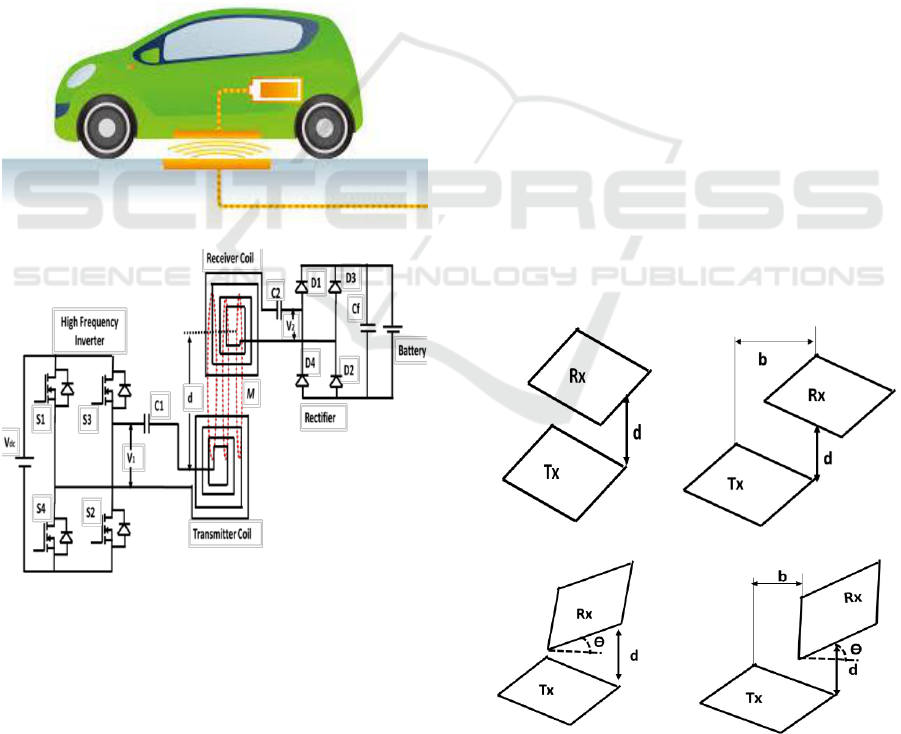
charging system is shown in Figure.1. The figure
gives the power flow in the WPT system.
The WPT system representation of schematic
diagram consists of High-frequency inverter,
transmitter, and receiver compensation circuits,
inductive coils and battery charging unit. The high-
frequency inverter converts the DC input supply to
high-frequency AC supply. The output of the
inverter is fed to power compensation circuits which
are used for performance improvement of the
wireless power transfer system. The transmitter and
receiver coil are connected to respective
compensation circuits. The power transfer takes
place between inductive coils maintained at the
proper air gap. Battery Charging unit includes
suitable power converters and the battery pack to be
charged and it is connected to the receiver side of
the system.
Figure 1: Basic schematic diagram of the WPT system.
This paper is organized into five sections.
Section 2 describes possible misalignment variation
of the square coils. Correspondingly finite element
modeling (Ansys Maxwell simulation) is presented
in section 3. Results and discussions are described in
section 4 and the conclusion is given in section 5.
2 POSSIBLE MISALIGNMENTS
IN SQUARE COUPLED COILS
This section presents the possible variations of
misalignments of the transmitter and receiver coils
such as perfect alignment, lateral or planar
misalignment and angular Misalignments. The
misalignments of the coupled coils are shown in
Figure. 2. Figure. 2(a) depicts the perfect alignment
of the transmitter and receiver coils i.e. the
coinciding axes of the flat planar surface. For
instance, when receiver coil is moved some more
distance away in vertical from transmitter coil the
flux linkages will decrease which as a result in a
decrement of mutual inductance. In the above case,
the coupling between them is weak. If transmitter
and receiver coils are perfectly aligned, and vertical
distance between them is very less, the flux linking
with the receiver coil is more, and the coupling
between them is strong. Also, the mutual inductance
is very high. Figure. 2(b) shows lateral misalignment
between the transmitter and receiver coil. In this
case transmitter and receiver, coils are placed in a
parallel plane and varied in horizontally. In
contradiction to the above two alignments, in
angular misalignment and Lateral and Angular
Misalignment (as shown in Figure.2 (c) to 2 (d)) the
mutual inductance between the coils depends on
horizontal, vertical distance and tilted angle since
they are placed at certain angle (0
o
to 30
o
) up or
down. In all the above misalignments the inductive
coupling characteristics are investigated.
(a)
(b)
(c)
(d)
Figure 2: Various misalignment of square inductive coils
(a) Perfect Alignment (b) Planar Misalignment, (c) Angu-
lar misalignment, (d) Planner and angular misalignment.
Performance Evaluation of Square Coupled Coils at Different Misalignments for Electric Vehicle Battery Charging
291
3 MODELING AND
DEVELOPMENT OF SQUARE
COUPLED COIL STRUCTURE
IN FEM (ANSYS MAXWELL)
Finite Element Modelling tool-ANSYS MAXWELL
is one of the world’s leading engineering simulation
tool for real-time simulations with design and
analysis of electromagnetic and electromechanical
devices, including motors, actuators, transformers,
sensors and coils. In this section, ANSYS
MAXWELL is employed to estimate the mutual
inductance and flux distribution of the square
coupled coil with different misalignments which
were discussed in section 2. In this software, all
simulations are carried out using 2-D FEM
modelling. Maxwell’s field distribution calculator
calculates the magnetic flux linked with the receiver
coil. The transmitter and receiver coils are
developed by the simulation tool with different
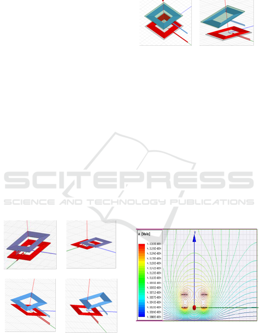
misalignment is as shown in Figure. 3. The FEM
coil setup with ferrite core for suitable applications
for EV battery charging are shown in Figure. 4.
In this modelling 0.25cm diameter solid copper
wires are used. Coil winding has started at a distance
of 4cm from their origin. Both the coils are made up
of equal number of turns as 12 and the gap between
each turn is 0.018cm, 16 x 16 x 0.1cm dimensioned
ferrite core and 24 x 24 x 0.2 dimensioned steel
chassis are used for transmitter and receiver coils.
The gap between core and coil is set to 0. 07cm.The
transmitter coil is energized by 5A AC current.
(a)
(b)
(c)
(d)
Figure 3: Square Coil arrangement in FEM Simulation (a)
Perfect Alignment (b) Planner Misalignment, (c) Angular
misalignment, (d) Planner and angular misalignment.
(a)
(b)
Figure 4: Square Coil arrangement in FEM Simulation (a)
Coil setup with Ferrite Core (perfect alignment), (b) Coil
setup with Ferrite Core (misalignment).
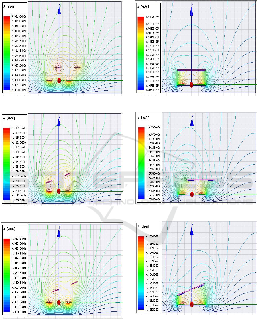
4 RESULTS AND DISCUSSIONS
The flux lines between the square inductive coupled
coils at 5cm vertical distance with different
misalignments for both air cored, ferrite cored and
ferrite core with chassis structure are shown in
Figure. (5), Figure. (6) and Figure. (7) respectively.
As if the receiver coil moves away from the
transmitter coil the flux linkage will reduce as a
result in reduction of mutual inductance.
The mutual inductances are computed between
the coupled coils with all misalignment conditions
which are the vertical distances 8cm, 12cm, 16cm,
20cm and 24cm for each horizontal distance such as
0cm, 5cm and 10cm and also for each angular
variation such as 0°, 15° and 30° for both at air
cored, ferrite cored and ferrite core with chassis
structure and it is shown in Figure.7. section must be
in one column.
(a)
Figure 5: 2-D Magnetic flux distribution between coupled
coils Without core (a) Perfect Alignment, (b) Planar
Misalignment, (c) Angular misalignment, (d) Planar and
angular misalignment.
VEHITS 2018 - 4th International Conference on Vehicle Technology and Intelligent Transport Systems
292
(b)
(c)
(d)
Figure 5: 2-D Magnetic flux distribution between coupled
coils Without core (a) Perfect Alignment, (b) Planar
Misalignment, (c) Angular misalignment, (d) Planar and
angular misalignment (cont.).
(a)
(b)
(c)
Figure 6: 2-D Magnetic flux distribution between the
coupled coils with core. (a) Perfect Alignment, (b) Planar
Misalignment, (c) Angular misalignment (d) Planar and
angular misalignment.
Performance Evaluation of Square Coupled Coils at Different Misalignments for Electric Vehicle Battery Charging
293
(d)
Figure 6: 2-D Magnetic flux distribution between the
coupled coils with core. (a) Perfect Alignment, (b) Planar
Misalignment, (c) Angular misalignment (d) Planar and
angular misalignment (cont.).
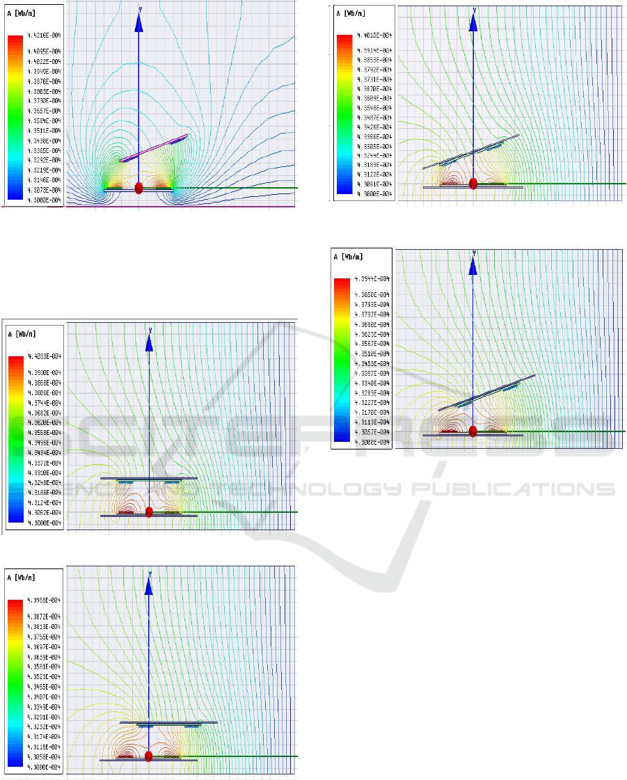
(a)
(b)
Figure 7: 2-D Magnetic flux distribution between the
coupled coils with core and chassis. (a) Perfect Alignment,
(b) Planar Misalignment, (c) Angular misalignment (d)
Planar and angular misalignment.
(c)
(d)
Figure 7: 2-D Magnetic flux distribution between the
coupled coils with core and chassis. (a) Perfect Alignment,
(b) Planar Misalignment, (c) Angular misalignment (d)
Planar and angular misalignment (cont.).
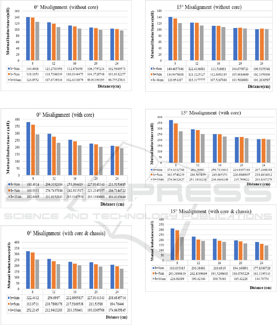
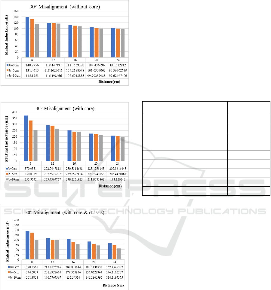
Figure 8(a), Figure 8(b) and Figure 8(c) give the
bar diagram of the MI values between the coupled
coil with perfect alignment without, with core and
with both core and chassis at all three cases of
horizontal distances and various vertical distance
and at 0° angular misalignments. Similarly,
Figure 8(d), Figure 8(e) and Figure 8(f) show the MI
values at 15° and Figure 8(g), Figure 8(h) and
Figure 8(i) at 30° angular misalignments.
From Figure 8 it is clear that the mutual
inductance decreases as the distance between the
coupled coils increases either in horizontally,
vertically or in angularly for both the cases such as
air core and ferrite core
VEHITS 2018 - 4th International Conference on Vehicle Technology and Intelligent Transport Systems
294
(a)
(b)
(c)
(d)
(e)
(f)
Figure 8: Graphical representation of MI vs Vertical
distances (a) 0° Misalignment (without core), (b) 0°
Misalignment (with core), (c) 0° Misalignment (with core
and chassis), (d) 15° Misalignment (without core), (e) 15°
Misalignment (with core), (f) 15° Misalignment (with core
and chassis), (g) 30° Misalignment (without core), (h) 30°
Misalignment (with core), (i) 30° Misalignment (with core
and chassis).
Performance Evaluation of Square Coupled Coils at Different Misalignments for Electric Vehicle Battery Charging
295
(g)
(h)
(i)
Figure 8: Graphical representation of MI vs Vertical
distances (a) 0° Misalignment (without core), (b) 0°
Misalignment (with core), (c) 0° Misalignment (with core
and chassis), (d) 15° Misalignment (without core), (e) 15°
Misalignment (with core), (f) 15° Misalignment (with core
and chassis), (g) 30° Misalignment (without core), (h) 30°
Misalignment (with core), (i) 30° Misalignment (with core
and chassis) (cont.).
5 CONCLUSIONS
This paper describes the inductive coupling
characteristics of the square coupled coils with
variations in distance between the coils vertically
and horizontally with different misalignment
conditions. Further it has been designed the
inductive coupled coils ferrite core and chassis. The
magnetic characteristics such as mutual inductance
is studied for different misalignments. It has been
concluded that by using ferrite core the magnetic
characteristics can be improved.
Table 1: Specifications of the Coils.
Description
Specifications
Number of turns in transmitter (N1)
12
Number of turns in receiver (N2)
12
Radius of the conductor
0.25 cm
Width of the coil
3cm
Inner length of the coils
4 cm
Ferrite core material
N96
Core dimensions
16*16*0.1 cm
Steel Chassis material
Stainless steel
Chassis dimensions
24*24*0.2 cm
REFERENCES
A. Khaligh and S. Dusmez, “Comprehensive Topological
Analysis of Conductive and Inductive Charging
Solutions for Plug-In Electric Vehicles” IEEE Trans.
Vehicular Technology, 61(8), pp. 3475–3489, Oct.
2012.
S. Li and C. Mi, "Wireless Power Transfer for Electric
Vehicle Applications," IEEE Journal on Emerging
and Selected Topics in Power Electronics, Vol.1. pp.
1-12, 2014.
G. A. Covic and J. T. Boys, “Modern trends in inductive
power transfer for transportation applications,” , IEEE
Journal of. Emerging Selected Topics in Power
Electronics, vol. 1, no. 1, pp. 28–41, Mar. 2013.
Roman Bosshard, Ugaitz Iruretagoyena and Johann W.
Kolar “Comprehensive Evaluation of Rectangular and
Double-D Coil Geometry for 50 kW/85 kHz IPT
System” IEEE Journal of Emerging and Selected
Topics in Power Electronics, Vol.4, No.4, Pp:1406-
1415, 2016.
Seho Kim, Grant A. Covic and John T. Boys “Tripolar
Pad for Inductive Power Transfer Systems for EV
Charging” IEEE Trans on Power Electronics, Vol.32,
No.7, Pp: 5045 – 5057, 2017.
VEHITS 2018 - 4th International Conference on Vehicle Technology and Intelligent Transport Systems
296

F. Y. Lin, G. A. Covic, and J. T. Boys, “Evaluation of
Magnetic Pad Sizes and Topologies for Electric
Vehicle Charging,” IEEE Trans. on Power
Electronics, Vol. 30, No. 11, pp. 6391-6407, 2015.
Chen, Kainan; Zhao, Zhengming;, “Analysis of the
Double-Layer Printed Spiral Coil for Wireless Power
Transfer,” IEEE Emerging and Selected Topics in
Power Electronics, vol. 1, no. 2, pp. 114-121, June.
2013.
A. P. Sample, D. A. Meyer, and J. R. Smith,“Analysis,
experimentalresults, and range adaptation of
magnetically coupled resonators for wireless power
transfer,” IEEE Trans. Ind. Electron., vol. 58, no. 2,
pp. 544–554, Feb. 2011.
Fariborz musavi and Wilson Eberle “Overview of
Wireless Power Transfer Technologies for Electric
Vehicle Battery Charging” IET Power Electronics,
7(1), pp.60-66, 2014.
C. Y. Huang, J. E. James, and G. A. Covic, “Design
considerations for variable coupling lumped coil
systems,” IEEE Trans. Power Electron, Vol.30, No.2,
pp. 680–689, Feb 2015.
Ezhil reena joy, Brijesh kumar, Gautam Rituraj and
Praveen Kumar “Impact of Circuit Parameters in
Contactless Power Transfer System” IEEE Conference
(PEDES), pp:1-6, 2014.
Dharavath Kishan, P S Nayak “Wireless Power Transfer
Technologies for Electric Vehicle Battery Charging –
A State of the Art”, Proceedings of IEEE International
conference on Signal Processing, Communication,
Power and Embedded System (SCOPES)-2016.
M. Budhia, G. A. Covic, and J. T. Boys, "Design and
Optimization of Circular Magnetic Structures for
Lumped Inductive Power Transfer Systems," IEEE
Trans. on Power Electronics, Vol. 26, No.11, pp.
3096-3108, 2011.
Yang Han and Xiaoping Wang “Calculation of Mutual
Inductance Based on 3D Field and Circuit Coupling
Analysis for WPT System” International Journal of
Control and Automation, Vol. 8, No. 4, pp. 251-266,
2015.
Merugu Kavitha, Phaneendra Babu Bobba and Dinkar
Prasad “Effect of Coil Geometry and Shielding on
Wireless Power Transfer System” 2016 IEEE 7th
Power India International Conference (PIICON).
Performance Evaluation of Square Coupled Coils at Different Misalignments for Electric Vehicle Battery Charging
297
