
Visual Inspection and Error Detection in a Reconfigurable Robot
Workcell: An Automotive Light Assembly Example
Tatyana Ivanovska
1
, Simon Reich
1
, Robert Bevec
2
, Ziga Gosar
3,4
, Minija Tamousinaite
1
, Ales Ude
2
and Florentin W
¨
org
¨
otter
1
1
Computational Neuroscience Department, University of G
¨
ottingen, G
¨
ottingen, Germany
2
Department of Automatics, Biocybernetics and Robotics, Joef Stefan Institute, Ljubljana, Slovenia
3
ELVEZ d.o.o., Ljubljana, Slovenia
4
Jozef Stefan International Postgraduate School, Ljubljana, Slovenia
Keywords:
Robotic Cell, Monitoring, Error Detection, Computer Vision.
Abstract:
Small and medium size enterprises (SMEs) often have small batch production. It leads to decreasing product
lifetimes and also to more frequent product launches. In order to assist such production, a highly reconfigurable
robot workcell is being developed. In this work, a visual inspection system designed for the robot workcell is
presented and discussed in the context of the automotive light assembly example. The proposed framework
is implemented using ROS and OpenCV libraries. We describe the hardware and software components of the
framework and explain the system’s benefits when compared to other commercial packages.
1 INTRODUCTION
Nowadays robots have become essential in multiple
industrial tasks. The robotic solutions are usually
applied for complex repetitive tasks and high unit
volume (Gaspar et al., 2017). However, in small
or medium-sized enterprises (SMEs) a few-of-a-kind
production scenarios (Kr
¨
uger et al., 2014) are more
typical. Since SMEs provide more than 40% of the
value added by the manufacturing industry in the Eu-
ropean Union (European commission, 2013), it is vi-
tal to allow them introduce efficient and easily recon-
figurable robotic solutions to ease and speed up the
product manufacturing.
To facilitate the production in SMEs, a recon-
figurable workcell is being developed and introdu-
ced (Gaspar et al., 2017) as a modular system, where
hardware and software components allow for fast and
easy reconfiguration.
In this paper, we present a visual monitoring sy-
stem, which is designed to detect errors during the
assembly process within the reconfigurable work cell.
We describe the hardware and software components
of the system and evaluate its applicability on the ex-
ample use case, namely, to the automotive light as-
sembly.
The paper is organized as follows. In Section 2,
the relevant information about the work cell develop-
ment as well as the available monitoring systems is
given. Section 3 presents the motivation for our de-
velopments. In Section 4, the use case details are
presented. In Section 5, the monitoring problem is
described and the measurement points are identified.
In Section 6, the proposed hardware and software so-
lutions are presented. The results are described and
analysed in Section 7. Section 8 concludes the paper.
2 RELATED WORK
Fulea et al. (Fulea et al., 2015) surveyed the litera-
ture on the topic of reconfigurability, focusing on in-
dustrial robotic workcells (as parts of reconfigurable
manufacturing systems), aiming to identify the main
approaches on reconfigurability and its relevant im-
plementations in the robotics (and related fields). Se-
tchi and Lagos (Setchi and Lagos, 2004) provided a
review of reconfigurability and reconfigurable manu-
facturing systems. Bi et al. (Bi et al., 2008) presen-
ted a survey of Reconfigurable Manufacturing Sys-
tems (RMS). It included general requirements of next
generation manufacturing systems and discussed the
strategies to meet these requirements.
Duro et al. focused on the applicability of the
Ivanovska T., Reich S., Bevec R., Gosar Z., Tamousinaite M., Ude A. and WÃ˝urgÃ˝utter F.
Visual Inspection and Error Detection in a Reconfigurable Robot Workcell: An Automotive Light Assembly Example.
DOI: 10.5220/0006666506070615
In Proceedings of the 13th International Joint Conference on Computer Vision, Imaging and Computer Graphics Theory and Applications (VISAPP 2018), pages 607-615
ISBN: 978-989-758-290-5
Copyright
c
2018 by SCITEPRESS – Science and Technology Publications, Lda. All rights reserved

Multicomponent Robotic Systems and Hybrid Intel-
ligent Systems for industrial tasks (Duro et al., 2010).
Gaspar et al. (Gaspar et al., 2017) presented a no-
vel automatically reconfigurable robot workcell that
addressed the issues of flexible manufacturing. The
proposed workcell is reconfigurable in terms of har-
dware and software. The hardware elements of the
workcell, both those selected off-the-shelf and those
developed specifically for the system, allow for fast
cell setup and reconfiguration, while the software
aims to provide a modular, robot-independent, Ro-
bot Operating System (ROS) based programming en-
vironment (Quigley et al., 2009). One of the innova-
tive hardware elements for this cell type is a flexible
fixture based on a Gough-Stewart platform called the
hexapod presented by Bem et al. (Bem et al., 2017).
An industrial monitoring problem is highly rele-
vant and has been studied in several research pro-
jects. For instance, the SCOVIS project investigates
the automatic work flow monitoring in a car assembly
environment in order to improve safety and process
quality (Kosmopoulos et al., 2012; M
¨
orzinger et al.,
2010; Voulodimos et al., 2011).
The monitoring of assembly processes is usu-
ally addressed by building customized solutions using
commercial framework packages as Halcon (Eckstein
and Steger, 1999) or Cognex (Scola et al., 2001) fra-
meworks. These frameworks are powerful and con-
tain multiple efficient algorithms for pattern recogni-
tion and image analysis. Another possible option is
to use other commercial frameworks (Matlab (Han-
selman and Littlefield, 2005)) or free libraries such as
OpenCV (Bradski, 2000).
3 MOTIVATION
Since the general project architecture suggests to use
the ROS framework (Gaspar et al., 2017), we look for
a software package or library that can be integrated
with ROS interface in a straightforward way.
To our knowledge, there is no straightforward way
to connect the ROS (Quigley et al., 2009) interface
with such frameworks as Halcon or Cognex software.
Moreover, the use of a commercial software would
increase the overall cost of the robot work cell. This
leverages the use of the free and open source systems
as ROS (Quigley et al., 2009) in combination with the
OpenCV library (Bradski, 2000).
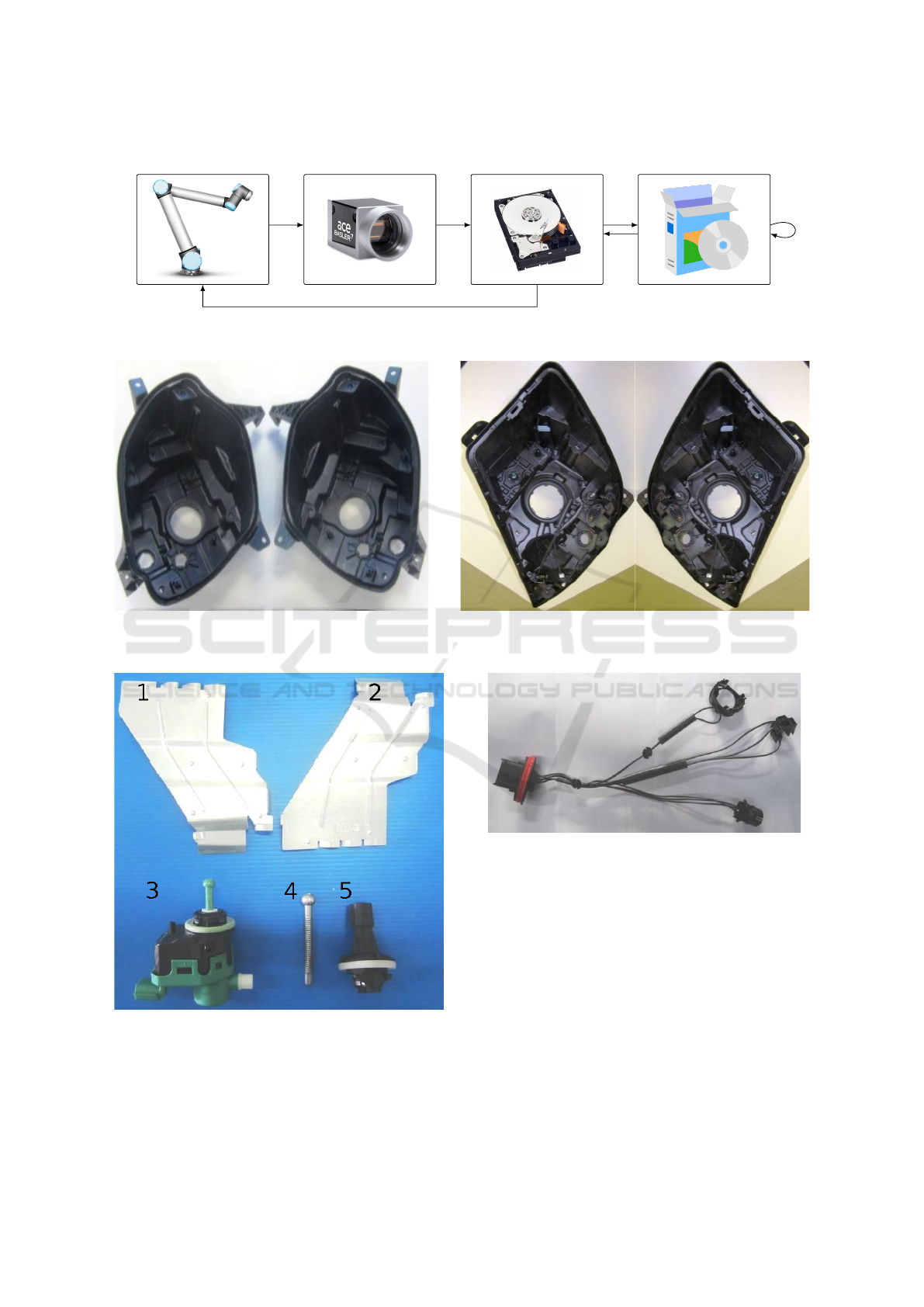
The processing using the well known software
as Halcon or Cognex can only be organized using
the procedure schematically shown in Figure 1. The
image must be obtained from the camera using the
ROS-based framework and saved on a hard drive.
Thereafter, the image can be read and processed by
a software package. The ROS node keeps listening
to the specified folder for the results. As soon as the
image processing is finished and saved, the ROS node
reads the results and sends a notification to the robot.
This solution is rather time-consuming and inef-
ficient. Hence, we have developed our own system,
which is completely integrated into the ROS frame-
work. Our system is based on OpenCV library, i. e.,
the main algorithm implementations are tested and
optimized. Several algorithms are combined into pro-
cessing pipelines, suitable for the example use case.
The main idea of our software package is to use fast
and efficient algorithms that do not require any prior
training due to the fact that for each task in each use
case the collection of a big amount of data seems in-
feasible.
Therefore, we propose a novel system, based on
OpenCV and ROS libraries, which is designed for
monitoring tasks in a robot workcell.
4 AN EXAMPLE USE CASE:
AUTOMOTIVE LIGHT
ASSEMBLY
Automotive lights (headlamps) are made up of typi-
cal rigid structural elements such as housing, actua-
tors, bulb holders, adjustable screws, heat shields, wi-
res and other components (Gaspar et al., 2017).
In Figure 2, two housings of car lights assembled
by ELVEZ company are shown.
There are several details that have been used for
robotic assembly. The components are listed below
and shown in Figures 2 and 3:
• Housing X07 or X82;
• LWR drive;
• Heat shields (left and right);
• Buld holder;
• Adjusting screw.
Such components as harness connection (cf. Fi-
gure 4) have been excluded as not suitable for the ro-
botic assembly.
5 QUALITY CONTROL TASKS
In general, visual inspection is to identify whether a
particular attribute is present, properly located on a
predetermined area, and not deviates from a given set
of specifications (Liu et al., 2015).
ROS System
Camera Harddrive
Software Packages
Figure 1: The image processing pipeline, when a software package is not straightforwardly combined with a ROS-based
system.
Figure 2: Two models of left and right automotive light housings produced by Elvez. Left: Housing X07; Right: Housing
X82.
Figure 3: Components for the assembly process. 1 and 2 are
the heat shields. 3 is the LWR Drive. 4 is the adjustment
screw. 5 is the light bulb holder.
There are two types of quality control tasks: a bi-
nary decision and a measurement. In the binary task,
Figure 4: An example of a harness connection. It was ex-
cluded from the automated assembly process.
the algorithm needs to make a decision, for instance,
if a detail is damaged or incorrectly placed. The mea-
surement task requires to measure a distance between
two details, a height of a screw, an angle of rotation
of the detail.
Whereas the first task can be implemented using
a camera, which has been only intrinsically calibra-
ted, the second task requires the extrinsic camera ca-
libration (Hartley and Zisserman, 2003) to obtain the
measurement results in physical units, for instance, in
mm. In this work, we describe and demonstrate the
solutions of the first type.
Here, we consider the following quality control
tasks:
1. Is a certain part of the housing damaged?
2. Is the screw properly assembled and no damages
occurred?
3. Is the LWR drive properly assembled and no da-
mages occurred?
4. Is the light bulb holder properly assembled and no
damages occurred?
6 METHODS
For our framework, we have chosen hardware and
software components that are described below.
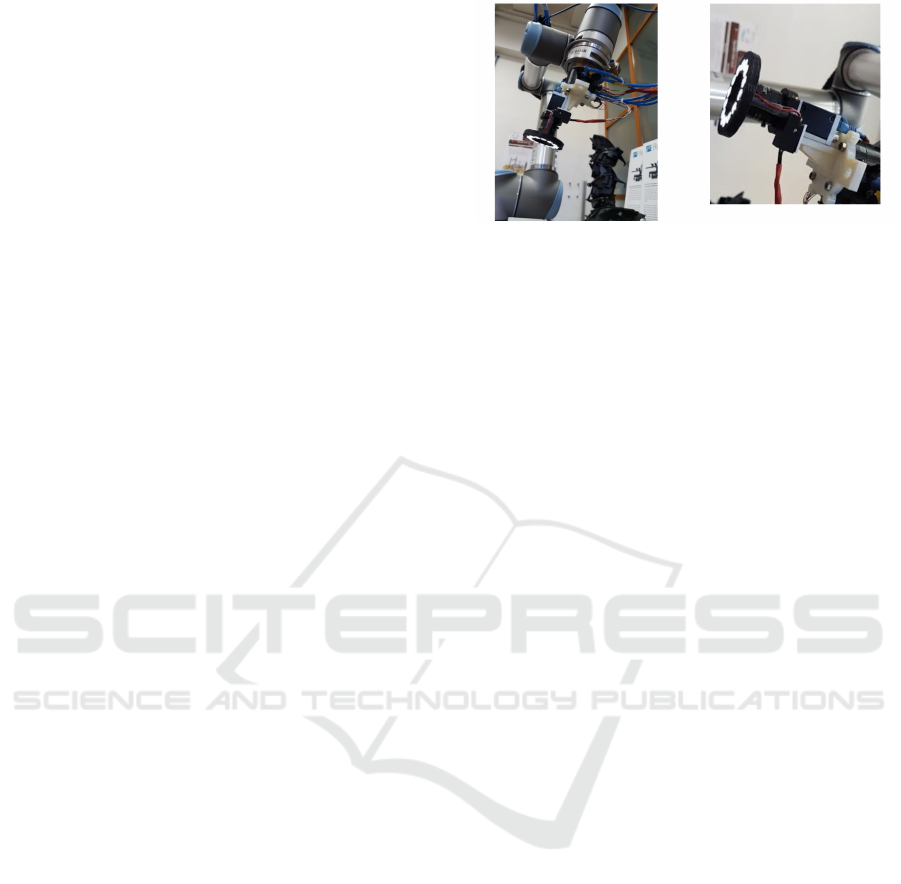
6.1 Hardware and User Pre-Setup
The monitoring of the execution and detection of er-
rors is performed in the workcell using a 2D color
camera (Basler acA4600-7gc), which is mounted to-
gether with a light ring to the robot using a pneumatic
tool changer system as seen in Figure 5. This system
allows the robot to release a gripper and pick up the
camera. This high resolution industrial camera pro-
duces 14MP images and has been selected to be able
to catch even minor detail damages and assembly in-
accuracies. The camera has a rolling shutter and a re-
latively low frame rate of 7 frames per second, which
makes the camera suitable only for situations where
the observed object is static relative to the camera.
As part of the reconfigurable workcell that our
proposed system is part of, the user has several ways
of planning the assembly sequence. It is possible to
use kinesthetic guidance in order to teach robotic se-
quences or use a simulation environment to design a
sequence. In both cases the user must define when
and where the visual inspections will be performed.
In this paper, we are proposing a solution for bi-
nary decisions, in which case camera plane alignment
is not so critical as in measurement inspections. That
means a user can use kinesthetic guidance or simu-
lation in order to select the camera pose for an ar-
bitrary inspection. There are several constraints that
must be obliged in order to come to a viable assem-
bly and inspection solution, e. g., the camera field of
view (lens), the robot configuration to reach the requi-
red camera pose (collision, workspace), and the cycle
time.
6.2 Software Solution
We have developed a framework, based on
OpenCV (Bradski, 2000) using ROS interface (Quig-
Figure 5: The industrial camera with a light ring mounted
on the UR-10 robot with the pneumatic tool changer system.
Left: a general view. Right: a close-up view.
ley et al., 2009), C++, and Qt (Summerfield, 2010).
The framework consists of several ROS modules,
where the central is the Monitoring one.
The image data stream is published through the
ROS module for the Basler camera. As soon as the
request for inspection arrives to the Monitoring ROS
module, it acquires the data from the camera, executes
the corresponding processing, and returns the status
of the operation (a boolean value, indicating, if the
detail is damaged or not). Additionally, a graphical
user interface is developed to demonstrate the moni-
toring routine.
6.2.1 The Processing Pipeline
First, ideal or template images are acquired (cf. Fi-
gure 6) and the corresponding regions of interest
(ROIs) are predefined by the user. After the templates
are defined, the actual processing of new image data
can be executed.
Second, the template ROI is detected in the ne-
wly acquired image. The search of the template starts
within a neighborhood of the ROI location in the ideal
image. The search is based on the assumption that the
ideal template and the actual image data are always
acquired under very similar conditions, namely, the
same controlled lighting and the pose. The template
image is overlaid with the corresponding patches of
the original image and in each point in a certain neig-
hborhood of the template location a normalized cor-
relation coefficient is computed. The location of the
global maximum is considered as the template loca-
tion (cf. Figure 7). Finally, the detected ROI of the
same size as the template image is extracted from the
acquired image and passed for further processing.
Third, the subimage preprocessing is executed.
Under preprocessing we understand illumination cor-
rection and denoising (Masters et al., 2009). It is
crucial to apply these techniques not on a full acqui-
red image, but on the extracted subimage to re-
duce the computational cost and the overall execution
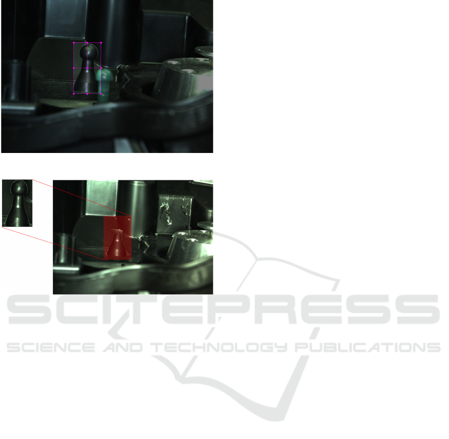
Figure 6: The process of template selection.
Figure 7: The process of template detection is schematically
shown. The template image (left) is sought in the acquired
image (right), and the region that is the most similar to the
template image is marked red.
time. The subimage is converted to the L*a*b co-
lor space (Reinhard et al., 2001), which is designed
to approximate human vision. The luminance chan-
nel (L) is extracted and the adaptive histogram equa-
lization (Reza, 2004) is applied to it. Thereafter, the
image is smoothed with median filter to preserve the
edges.
Fourth, the use case-specific checks are executed.
Usually, they include a segmentation step to extract
the contours of the detail of interest, for example,
using color global or local, automatic or manual thres-
holding. For the automatic thresholding, the Otsu
thresholding (Zhang and Hu, 2008) is applied. The-
reafter, connected components (Masters et al., 2009)
are checked, and the component of interest is found
and analyzed.
6.2.2 Framework Modes
The framework has three following modes:
• Template selection (online or offline);
• Offline processing pipeline testing;
• Online monitoring.
After the template selection, the user can test the
developed detection pipelines and check different pa-
rameter settings on an image, acquired from the ca-
mera directly or saved on a hard drive.
In the current version of our framework, the pro-
cessing pipelines are pre-programmed. The next ver-
sion the user will be able to generate and save the pro-
cessing pipelines.
6.2.3 Use Case-specific Algorithms
Here, we describe the algorithms that have been de-
veloped for the automotive light assembly use-case.
Damage on the Housing Part. An example is
shown in Figure 7. In this task, the shape of the detail
as well as its intensity are analysed.
The shape of the detail top is assessed using the
Hough transform algorithm for circle detection (Mas-
ters et al., 2009).
The top circles are detected both in the template
and the ROI images. If the distance d between the
circle centers c
1
and c
2
and differences between the
radii are greater than a user defined threshold T , the
detail is considered to be damaged:
(
d(c
1
, c
2
) >= T Damaged
d(c
1
, c
2
) < T OK
(1)
For the intensity analysis, the template and the ROI
images (I
t
and I
ROI
, respectively) are converted to the
HSV color space (Masters et al., 2009), and the abso-
lute differences between the intensity values are com-
puted: |HSV (I
t
) − HSV (I
ROI
)|. The total number of
pixels, where the difference value is greater than a
user defined threshold, is evaluated.
In Figure 8, an example of the ROI extracted in
Figure 7 is shown. Since the detail is damaged, the
Hough transform fails to detect the circle in the ROI,
and the expected circle location is marked red. The
parts, where the differences with the template image
are significant are marked white. As it can be obser-
ved, most of the differences are located in the dama-
ged region.
Detection of the Screw Height. Basically, it is re-
quired here to detect if the screw height lies in a user-
defined range. In this case, a screw base is selected as
a suitable template (cf. Figure 4).
When the template is detected, the coordinates of
its top left corner [x
1
, y
1
] and the bottom right corner
[x
1
+ w, y
1
+ h] are given, where w, h denote the width
and height, respectively. To extract a region, which
contains the screw, the following coordinates are ta-
ken: [x
1
, 0], [x
1
+ w, y
1
]. Thereafter, the preprocessing
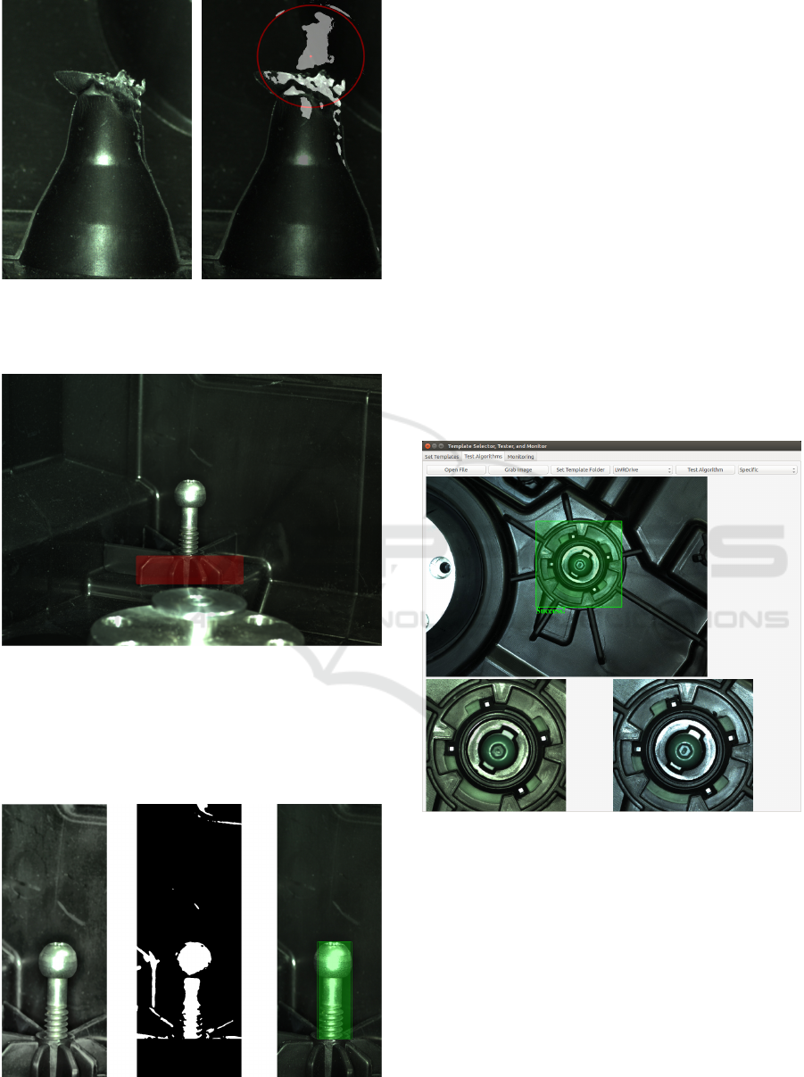
Figure 8: Left: the acquired image of the damaged detail.
Right: The processing results are overlaid with the acquired
image.
Figure 9: The base of the screw is a template, since this part
does not change from image to image.
procedure described above is utilized. Finally, Otsu
thresholding (Zhang and Hu, 2008) is applied to the
image.
Figure 10: The screw is detected using connected compo-
nent analysis.
From the thresholding result the two biggest con-
nected components are extracted and their total height
is measured (cf. Figure 10). If the height H of the
screw does not lie in a predefined range, the case is
rejected:
(
T
hmin
≤ H ≤ T
hmax
OK
Otherwise Reject
(2)
Detection of the Detail Position. Here, both pro-
blems of the LWR drive and the bulb holder positi-
oning are solved with a similar processing pipeline.
Basically, the template is detected and then the ex-
tracted region of interest (ROI) is compared to the
template image. If the differences between the ima-
ges are higher than a certain threshold the case is re-
jected. In Figures 11 and 12, screenshots from our
framework, acquired in the Testing mode are shown.
The LWR drive is properly placed, whereas the image
with the bulb holder is rejected.
Figure 11: The detection result is positive.
7 EVALUATION AND
DISCUSSION
We analyze the presented hardware and software
components as well as discuss the advantages and li-
mitations of the system.
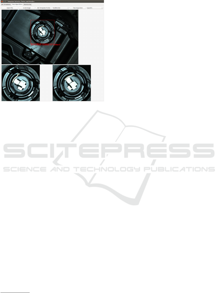
Figure 12: The assembly was not successful.
7.1 Hardware Components
Today the market of industrial imaging offers multi-
ple 2D and 3D cameras. For instance, such companies
as ”The Imaging Source“
1
or Basler
2
present indus-
trial cameras, which can be successfully applied for
the monitoring task. Apart from that, these manufac-
turers support a multi-platform application program-
ming interface (API).
Moreover, there is a specialized ROS module for
Basler cameras, which is naturally built in the gene-
ral software architecture of the reconfigurable work
cell (Gaspar et al., 2017).
We have selected a color high resolution (14 MP)
Basler camera, which allows for up to 7 frames per
second. The resolution is 4608px × 3288px. This ca-
mera can only be used for acquisition of still images,
i. e. the robot moves to a certain position, stops, and
the image is taken. For such tasks as video tracking,
this camera is not suitable.
For the selection of the appropriate lens, several
parameters have to be taken into account. The main
ones are the object size and the working distance. The
sensor size and the lens mount are defined by the ca-
mera. Since the size of the imaged objects can be
rather small, e. g. 10 × 20 mm
2
, and considering the
sensor size, we have selected a f 25 mm lens with a
working distance 200 mm.
1
https://www.theimagingsource.de
2
https://www.baslerweb.com
7.2 Software Components and
Algorithms
We observed that measurement problems are very dif-
ferent even for the same use case. Hence, only limited
generalization with respect to processing algorithms
is possible. Namely, one is not able with the same al-
gorithm to measure the height of a metal screw and
detect, if some other plastic detail is intact. The gene-
ral evaluation pipeline consists of the following steps:
1. Template detection
2. ROI selection
3. ROI pre-processing (denoising and illumination
correction)
4. Segmentation and object extraction
5. Object evaluation (distance or angle measure-
ment, binary decision)
The first three steps are rather general, and we use
them for all measurement problems. Of course, prior
to measurements, the user has to set up the templates
for each problem.
For the first step, the template matching al-
gorithm provided by OpenCV is applied. We
observed that only normed metrics (for instance,
CV_TM_CCORR_NORMED) work reliably for our pro-
blems. This straightword template matching is ap-
plicable, when the assumption about the controlled
lighting conditions holds. In a more general set up,
this algorithm can be replaced with a more sophisti-
cate object detection using descriptors, for example,
SURF (Zhang and Hu, 2008).
The latter two steps are task-dependent. For
segmentation and object extraction we usually ap-
ply some prior knowledge about the object appea-
rance, e. g., color, shape, and location on the image.
Here, such algorithms as color clustering or threshol-
ding, and shape analysis (Hough transformation, Har-
ris corner detection, Connected component analysis)
are applicable.
For each measurement problem, we collected test
images, acquired in a test environment as well as the
real images, obtained during the assembly procedure.
The parameters were pre-selected and optimized for
the implemented use case.
A new use case, i. e. with new measurement tasks,
the algorithmic pipelines and their correspondent pa-
rameters would have to be again selected and optimi-
zed. However, we assume that a set of image pro-
cessing tools provided by the OpenCV library, such
as pattern matching, denoising, segmentation, and fe-
ature extraction algorithms would be fully sufficient
for a monitoring task.

Although the presented framework for visual in-
spection is efficient and completely integrated with
the whole robotic work cell, it has certain limitations.
First, the hardware choice is suitable for inspection of
static images, but it is not suitable for video tracking.
Second, the whole software system is tied to a speci-
fic ROS version, which is not downwards compatible.
Third, the generation new processing pipelines would
require from the user some knowledge on image ana-
lysis and robotics. Fourth, new templates will have
to be generated and the parameters will have to be
re-optimized, if the robot poses or lighting conditions
change, which can be a rather time-consuming task.
8 CONCLUSIONS AND FUTURE
WORK
The computer vision framework, which is used as a
monitoring module in a highly reconfigurable robot
workcell has been presented here. The hardware as
well as software components were described and dis-
cussed. The automotive assembly use case example
was used as an application example.
As future work, we will extend the software com-
ponents to allow the user to generate processing pi-
pelines as well as test the framework on further use
cases.
ACKNOWLEDGEMENTS
The research leading to these results has received fun-
ding from the European Communitys Horizon 2020
Programme under grant agreement no. 680431, Re-
conCell(A Reconfigurable robot workCell for fast set-
up of automated assembly processes in SMEs).
REFERENCES
Bem, M., Deni
ˇ
sa, M., Ga
ˇ
spar, T., Jereb, J., Bevec, R.,
Kova
ˇ
c, I., and Ude, A. (2017). Reconfigurable fix-
ture evaluation for use in automotive light assembly.
In Advanced Robotics (ICAR), 2017 18th Internatio-
nal Conference on, pages 61–67. IEEE.
Bi, Z. M., Lang, S. Y., Shen, W., and Wang, L. (2008).
Reconfigurable manufacturing systems: the state of
the art. International Journal of Production Research,
46(4):967–992.
Bradski, G. (2000). The opencv library. Dr. Dobb’s Jour-
nal: Software Tools for the Professional Programmer,
25(11):120–123.
Duro, R. J., Gra
˜
na, M., and de Lope, J. (2010). On the po-
tential contributions of hybrid intelligent approaches
to multicomponent robotic system development. In-
formation Sciences, 180(14):2635–2648.
Eckstein, W. and Steger, C. (1999). The halcon vision sy-
stem: an example for flexible software architecture.
In Proceedings of 3rd Japanese Conference on Practi-
cal Applications of Real-Time Image Processing, pa-
ges 18–23.
European commission (2013). Factories of the future:
Multi-annual roadmap for the contractual ppp under
horizon 2020. Publications office of the European
Union: Brussels, Belgium.
Fulea, M., Popescu, S., Brad, E., Mocan, B., and Murar,
M. (2015). A literature survey on reconfigurable in-
dustrial robotic work cells. Applied Mechanics and
Materials, 762:233.
Gaspar, T., Ridge, B., Bevec, R., Bem, M., Kova
ˇ
c, I., Ude,
A., and Gosar,
ˇ
Z. (2017). Rapid hardware and soft-
ware reconfiguration in a robotic workcell. In Advan-
ced Robotics (ICAR), 2017 18th International Confe-
rence on, pages 229–236. IEEE.
Hanselman, D. C. and Littlefield, B. (2005). Mastering mat-
lab 7. Pearson/Prentice Hall.
Hartley, R. and Zisserman, A. (2003). Multiple view geome-
try in computer vision. Cambridge university press.
Kosmopoulos, D. I., Doulamis, N. D., and Voulodimos,
A. S. (2012). Bayesian filter based behavior recog-
nition in workflows allowing for user feedback. Com-
puter Vision and Image Understanding, 116(3):422–
434.
Kr
¨
uger, N., Ude, A., Petersen, H. G., Nemec, B., Ellekilde,
L.-P., Savarimuthu, T. R., Rytz, J. A., Fischer, K.,
Buch, A. G., Kraft, D., et al. (2014). Technologies
for the fast set-up of automated assembly processes.
KI-K
¨
unstliche Intelligenz, 28(4):305–313.
Liu, Z., Ukida, H., Ramuhalli, P., and Niel, K. (2015). In-
tegrated Imaging and Vision Techniques for Industrial
Inspection. Springer.
Masters, B. R., Gonzalez, R. C., and Woods, R. (2009). Di-
gital image processing. Journal of biomedical optics,
14(2):029901.
M
¨
orzinger, R., Sardis, M., Rosenberg, I., Grabner, H., Ve-
res, G., Bouchrika, I., Thaler, M., Schuster, R., Hof-
mann, A., Thallinger, G., et al. (2010). Tools for semi-
automatic monitoring of industrial workflows. In Pro-
ceedings of the first ACM international workshop on
Analysis and retrieval of tracked events and motion in
imagery streams, pages 81–86. ACM.
Quigley, M., Conley, K., Gerkey, B., Faust, J., Foote, T.,
Leibs, J., Wheeler, R., and Ng, A. Y. (2009). Ros: an
open-source robot operating system. In ICRA works-
hop on open source software, volume 3, page 5. Kobe.
Reinhard, E., Adhikhmin, M., Gooch, B., and Shirley, P.
(2001). Color transfer between images. IEEE Com-
puter graphics and applications, 21(5):34–41.
Reza, A. M. (2004). Realization of the contrast limited
adaptive histogram equalization (clahe) for real-time
image enhancement. The Journal of VLSI Signal Pro-
cessing, 38(1):35–44.

Scola, J. R., Ruzhitsky, V. N., and Jacobson, L. D. (2001).
Machine vision system for object feature analysis and
validation based on multiple object images. US Patent
6,175,644.
Setchi, R. M. and Lagos, N. (2004). Reconfigurability and
reconfigurable manufacturing systems: state-of-the-
art review. In Industrial Informatics, 2004. INDIN’04.
2004 2nd IEEE International Conference on, pages
529–535. IEEE.
Summerfield, M. (2010). Advanced Qt Programming: Cre-
ating Great Software with C++ and Qt 4. Pearson
Education.
Voulodimos, A., Kosmopoulos, D., Vasileiou, G., Sardis,
E., Doulamis, A., Anagnostopoulos, V., Lalos, C., and
Varvarigou, T. (2011). A dataset for workflow re-
cognition in industrial scenes. In Image Processing
(ICIP), 2011 18th IEEE International Conference on,
pages 3249–3252. IEEE.
Zhang, J. and Hu, J. (2008). Image segmentation based on
2d otsu method with histogram analysis. In Computer
Science and Software Engineering, 2008 Internatio-
nal Conference on, volume 6, pages 105–108. IEEE.
