
Intelligent and Flexible Worker Assistance Systems
Assembly Assistance Platform for Planning Assisted Assembly and Rework
as Well as Execution of a Worker-Centered Assistance
Rainer Mueller, Matthias Vette-Steinkamp, Leenhard Hoerauf, Christoph Speicher
and Attique Bashir
Center of Mechatronics and Automation Technology, Eschberger Weg 46, 66121 Saarbruecken, Germany
Keywords: Worker Assistance, Manual Assembly, Rework Station, Industry 4.0.
Abstract: In assembly, reworking stations are often barely automated work places, where no technical equipment
supports the worker, validates the process execution or documents process results. However, worker
assistance systems are used to guide and support the worker through manual assembly. Nevertheless, the
concept of providing information to the worker is limited to screen based output media and assistance systems
are just compatible to supplier selected devices. The objective of the presented research and development in
this paper is an interactive worker assistance system which combines qualification-based worker support and
intelligent process validation especially for rework stations. Beside the worker assistance system, a planning
environment is developed for an efficient generation of work plans and content for the worker assistance
system.
1 INTRODUCTION
Nowadays, manufacturers are confronted with many
challenges such as market demands for high quality
products and decreasing prices. At the same time, the
demand for individualized products raises which
results in an increasing product variety and in smaller
batch sizes at the manufacturer’s side. To satisfy these
customer demands, manufacturer have to find the
right way to combine the flexibility of manual
processes and the reliability of automated systems.
(Mueller, 2016a)
In most industrialized countries, the described
challenges paired with the demographic development
intensifies the situation and the need for supporting
systems in manual assembly. According to (Weidner
et al., 2015), supporting systems can be distinguished
between technical systems that substitute humans and
systems that support humans. Furthermore, they state
that a technical system can be considered as
supporting system if it fulfills the following points:
1. The technical system supports the worker with his
tasks, without replacing him
2. The technical system can always be overruled by
the worker
3. The worker operates the technical system
4. The system does not pose any danger for the
worker
Beyond that supporting systems consider physical,
psychological, communicative or organizational
improvement. An assistance system is a supporting
system that can be distinguished in systems for
physical or informational support (Hinrichsen et al.,
2016).
In final assembly lines, these supporting systems
are frequently implemented to guide the worker
through the assembly process. Whereas in rework
areas, experienced workers do the rework without the
help of an assistance system because standard
assistance systems do not possess the ability to handle
dynamic failure conditions. Furthermore, these
systems obstruct the worker during his work because
they do not consider the experience level of the
worker. Due to the minor application of assistance
systems at rework area, failures occurring during
manual rework process aren’t detected in time and
cause expensive reworks again.
This paper presents the development of an
assembly assistance platform. The platform’s purpose
is planning assisted processes through use of the
worker assistance system, guiding the worker through
the job and rework process validation in industrial
production. The platform consists of a planning
Mueller, R., Vette-Steinkamp, M., Hoerauf, L., Speicher, C. and Bashir, A.
Intelligent and Flexible Worker Assistance Systems - Assembly Assistance Platform for Planning Assisted Assembly and Rework as Well as Execution of a Worker-Centered Assistance.
DOI: 10.5220/0006613900770085
In Proceedings of the 13th International Joint Conference on Computer Vision, Imaging and Computer Graphics Theory and Applications (VISIGRAPP 2018) - Volume 2: HUCAPP, pages
77-85
ISBN: 978-989-758-288-2
Copyright © 2018 by SCITEPRESS – Science and Technology Publications, Lda. All rights reserved
77

environment to design dynamic process flows and a
control system. The control system connects planning
environment, worker assistance system and
intelligent resources.
The ongoing research and development of the
assistance platform is presented in following
chapters: Chapter 2 gives an overview of the state of
the art. Chapter 3 de1scribes the current situation and
requirements for worker assistance in the rework
station of an automotive supplier. In Chapter 4 the
developed solution is presented, beginning with a
short analysis of current worker assistance systems
which are found in manufacturing companies
nowadays. Chapter 5 summarizes the results of the
research work and gives an outlook towards future
work.
2 STATE OF THE ART
To support the worker cognitively during manual
processes, conventional media such as paper, tables
and other drawings are widely used (Wiesbeck,
2014). However, these traditional concepts have the
disadvantage that employees have to look at different
objects and search for the correct information by
flicking through the instructions. This is time
consuming (Lusic and Fischer, 2016) and hinders the
parallel handling of the product. The information
supply is not efficient by using this unsuitable display
techniques and can lead to assembly errors e.g. due to
misinterpretation. These manuals are time-invariant,
and therefore cannot represent information in
temporal sequences directly. Hence, they burdens
more cognitive load to the worker (Lusic and Fischer,
2015). Furthermore, manuals have to be updated
contently and physically if they are available as
printouts because they do not have any direct link to
a digital planning environment. Process instructions
written down on paper are more likely to be ignored,
due to the extra handling effort.
Therefore, analogue and conventional
information carriers have to be substituted by digital
media and to provide the information in the most
ergonomic way to the worker. The information
representation is just one part of the assistance. It
avoids failures by providing the worker with
information for the right execution of the process.
However, the second part is to check if a supposed
completed process is executed as specified. Thus,
assistance systems are equipped with sensors to
evaluate the process. For example, camera
technology is widely used to compare target state and
actual state of a process.
Currently, there are several worker assistance
systems available on the market. Looking at them
reveals different stages of assistance. The main
component of assistance systems is their information-
displaying character. Moreover, they often have an
evaluating component like cameras to detect
differences between actual status and target status of
the process or rather of the product.
A closer look at the available cognitive assembly
assistance systems reveals that these systems consist
mostly of two parts. The first part is the planning
environment, whereas the second part is used to
support the worker during the processes. In the
planning environment, the user or a planner defines
the processes and parameters which are used during
the process later. The following characteristics are
found in most worker assistance systems:
▪ Listing of processes to be executed
▪ Pointing to the current process (to be finished)
▪ Illustration of the process
▪ Manual quitting of the process
These systems are often restricted to the provider’s
specific resources. Even though they integrate several
systems like pick-by-light, the amount of available
resources integrated in the assistance system is
limited. Moreover, most common worker assistance
systems are limited to a worker guidance which
appears in the form of a monitor with a job list and
further human readable information like figures.
Sometimes, there is only one sensor like a push button
for quitting the process. Planning environments are
used to configure the assistance systems, but are
limited to integrate further resources. Because of this,
processes with other resource requirements cannot be
listed on the job list. E.g. camera based systems
cannot validate the torque applied in a tightening
process. Especially in the manual assembly or rework
station where a lot of complicated and different kinds
of processes have to be validated, the limitation of
hedging technologies can be seen as insufficient.
Most environments generate process lists by defining
them step by step. These static job lists are unsuitable
for a huge amount of variants as well as error code
dependent rework processes. An error code
corresponds to a defective behavior of the product
and allows to determine the reason of the failure. It is
provided by a test bench. However, changing the
rework job is quite common because another failure
reasons can be detected by the worker during the
process execution.
Therefore, the system must pose the functionality
to change the rework job dynamically on an error
code, which is not provided by common systems.
HUCAPP 2018 - International Conference on Human Computer Interaction Theory and Applications
78

3 ANALYSIS OF THE INITIAL
SITUATION
As the assembly assistance platform is developed for
the application in real production environment, the
conditions and initial situation are analyzed
beforehand. The case is the assisted and ensured
rework on faulty automatic transmissions after the
final assembly and commissioning in production. As
an automotive supplier, the transmission
manufacturer faces high quality demands and is
obligated to secure and document its processes. Due
to the operational structure and economic reasons,
this is achieved in the final assembly but not in the
rework area.
An automatic transmission is made of a large
quantity of parts which are assembled through
complex processes. In the final assembly, (semi-
)automated assembly lines are installed which
provide a high degree of process validation as well as
an extensive process documentation. The process
validation results in high quality manufactured
products. To validate the processes, the assembly
lines are equipped with sensors and electronic
resources that ensure the correct assembly process
execution. In a testing bench, additional tests are
performed to validate the quality and functionality.
Faulty transmissions are sent together with an error
code to the rework stations in order to get repaired
and brought in a salable state.
In contrast to the final assembly lines, rework
stations are structured as single workplaces and are
dominated by a high degree of manual assembly
processes. This allows a required degree of flexibility
to repair all kinds of product variants and perform
different rework jobs and processes at one workplace.
But compared to the final assembly lines, the process
validation and documentation in the rework station
are insufficient, due to the lack of automated and
technical equipment. Hence, highly skilled workers
are needed which additionally undergo a special
training program to be able to handle the rework job.
Especially the lack of process validation can lead to
mistakes during the process. In the final assembly
line, the process validation ensures the correct and
scheduled performance of a process as well as process
documentation, which is necessary for traceability
purposes to customers.
Since rework jobs require highly qualified
workers with many years of experience, in case of
sudden absence personal replacement cannot be
found easily. Furthermore, experienced worker
undergo a capacity intensive training to be qualified
to work at the rework area. Thus, one objective of the
proposed assembly assistance platform is to reach a
similar degree of process validation as in final
assembly lines, but maintain the workers’ adaptivity
and ability to make situation based decisions. Another
objective is to cover worker qualification and training
on the job. Therefore, the assembly assistance
platform consists of four important modules:
▪ Assistance system for guiding and qualifying
workers
▪ Intelligent resources to validate and document the
processes
▪ A control system that distributes planning data to
resources and assistance system and connects all
systems with each other
▪ A planning environment for creating dynamic and
parametrized processes lists
The worker assistance system has to guide the worker
through the rework job and support him to avoid any
mistakes.
Following, the user profile is described. The
developed system addresses women and men alike
and there is no difference in the information/ content
provided by the system or how the content is
displayed. The user’s age varies from early 20s to 60.
Therefore, IT-affine and non-affine people alike are
confronted with the system in their daily work. To
address both types of users, users will be qualified
and trained for working with the system.
Furthermore, the user is involved in the design phase
of the system and has the opportunity to give
feedback concerning the design of the assistance
system. As mentioned before, the average user is a
skilled worker with at least three years of work
experience in a similar production department, where
similar but often “easier” tasks have to be performed.
Hence, the user is familiar with the basic
functionalities of the product (automatic
transmission). Because a lot of product variants and
different process have to be mastered, three skill
levels (beginner, advanced and expert) have to be
considered. Beginner starting in the rework area are
supported by experts and trained for about half a year.
He needs a higher grade of assistance e.g. of difficult
processes and resource because he is still in learning
phase and has to be trained. Users exceeding the
training phase are of course more experienced. On
this level, they don’t need small stepped assistance
and further explanation of processes, but additional
hints or information e.g. during a bolt tightening
process considering the tightening sequence or during
the rework on a variant, which they don’t handle /
repair very often. Experts on the other hand don’t
need any hints. On this level, assistance is seldomly
needed and detailed information is considered
Intelligent and Flexible Worker Assistance Systems - Assembly Assistance Platform for Planning Assisted Assembly and Rework as Well as
Execution of a Worker-Centered Assistance
79

disturbing rather than helpful. Therefore, the
assistance system will provide only information about
major repair steps and most importantly, give
feedback to successful or faulty processes during
repair. This last point was addressed by beginners and
experts alike. To close the loop between human action
and system behavior or rather the performed task a
feedback from the assistance system is given. The
feedback informs the user if a process is quit as
planned or if something needs to be considered there.
It needs to be considered that workers considered
experts don’t have more decision rights. The main
difference is the degree of assistance, which is needed
to complete the task.
The rework job is a set of processes which
consists of three stages: the disassembling, the
repairing process and the assembling of the product.
Because of many different error codes in combination
with a high amount of product variants, the worker
assistance system has to generate the process and job
list dynamically. Since the relationship between error
code and job list is not unique, the worker should have
the opportunity to take another process and job list, if
he detects another reason for the error aside from the
given job list code. Therefore, the assembly
assistance platform has to allow a dynamic and
resource independent generation of process
sequences and an easy integration of resources.
Since the assembly assistance platform is used at
the rework area, there are four requirements
formulated which are similar to (Aehnelt and Urban,
2015):
1. Information
2. Parametrization of resource and process execution
3. Monitoring and checking
4. Documentation
Information considers the ability of a system to
provide the user with human readable data. A
visualization complements the pure textual
information as well as other forms of visualization by
showing how and where to handle parts.
Parametrization and process execution concerns
the data for smart resources. E.g. electronic resources
can be configured through parametrization.
Electronic bolt tightening tools often have the
capability to drive a predefined bolt tightening curve
and tighten bolts with certain parameters.
Continuous monitoring and checking of the
process can be validated. As long as the current
process is not quitted the worker knows that the
process is not completed as planned. In case of a
system failure, most assistance systems allow the
worker to quit a process manually if the worker is sure
that a process is finished correctly.
Documentation is mostly the last action of a process.
If the process is finished certain process parameters
have to be stored due to traceability purposes.
Every requirement listed above is fulfilled by a
resource of the assembly assistance platform. E.g. the
first requirement of the assembly assistance system is
to provide the worker with information. The resource
which can be used for that is a monitor. The second
requirement is to execute the process. For this, a smart
resource can be used. So for every requirement listed
above a resource can be used to fulfill it.
4 DEVELOPMENT OF AN
ASSEMBLY ASSISTANCE
PLATFORM FOR THE
MANUAL ASSEMBLY
To use the assembly assistance platform in a modern
factory environment, the following requirements and
boundary conditions are considered:
1. The planning environment can use already
existing data e.g. from the product design
department
2. The planning environment is user friendly and can
be used easily without any programming
experience
3. The planning environment can handle multiple
product variants
4. The planning environment can store the plan data
in a suitable way so that a control system can use
these data
5. The control system can read error codes and
variant codes to generate a rework job list from an
existing overall process list dynamically
6. The worker assistance system allows to
dynamically expand the rework job if another
failure reason is assumed
7. Additional resources can be easily integrated into
the worker assistance system
8. The worker guidance offers reporting and
feedback possibilities
Beside the analysis of final assembly as well as
current state of rework area, the requirements
considering the product and processes are also
analyzed. Based on the analysis of the initial situation
and a performed Failure Mode and Effects Analysis
(FMEA), the critical product parts and processes
which have to be validated during rework by the
resources and functions of the assembly assistance
platform are documented. As a result, the following
requirements have to be considered and provided by
the assembly assistance platform:
HUCAPP 2018 - International Conference on Human Computer Interaction Theory and Applications
80
1. Checking if the right part is removed or assembled
as well as positioned (e.g. tolerances) correctly
2. Checking if a disassembled part is placed in a
defined component tray
3. Checking if a disassembled part is disposed as
anticipated
4. Checking if the correct part is picked and
assembled in the product
5. Checking if a process is performed as planned e.g.
if a bolt tightening operation is executed correctly
regarding tightening process, torque, angle and
sequence
With the understanding of product, process and
resources as well as the boundary conditions and
requirements, the concept for the assistance platform
is developed. The assembly assistance platform
consists of four different modules. In Figure 1, the
concept and framework of the platform with different
modules is shown and unites the planning
environment as well as the worker assistance system.
Besides, the human role can be seen. The role is
mainly to perform processes on the product. The
worker guidance is the main interface between human
and worker assistance system. It provides the user
with main information about the product as well as
the process but also allows to give feedback e.g. when
a process needs to be quit. Another way to provide
information to the user is by using the smart
resources. Whenever the resources are not supposed
to be used, they are disabled, which is a hint to the
user that he eventually missed a step before or didn’t
commit it correctly.
Figure 1: Worker assistance platform consisting of a
planning environment and worker assistance system.
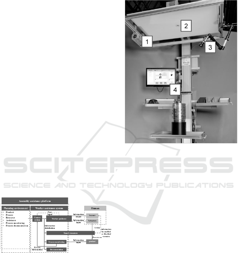
In Figure 2, the current state of the worker
assistance system with implemented resources is
shown. As for now, it consists of a 2D camera, an IR-
Camera, a laser projector and a worker guidance
system. Further resources and functionalities to fit the
described requirements are planned.
Figure 2: Current state of the work station with laser
projector (1), 2D Camera (2), IR camera (3) and a worker
guidance system (4).
4.1 Planning Environment to
Configure Assisted Job Lists
To setup the worker assistance system, a planning
environment is needed. To reduce programming
effort, the planning environment has a GUI. Since the
execution of the processes leads to the completion of
the rework, the aim of the planning system is
primarily to generate a resource afflicted generic
process list (generic rework job list). The list allows
to repair any component of any product variant and
even helps handling the worst case scenario in which
all components need to be replaced (or repaired).
Therefore, the list contains all assemblies,
subassemblies and parts (hereinafter referred to as
product components) of the product’s variant group.
The approach to create that list is to begin with
analyzing the product, derive the processes and assign
the appropriate resources.
Initial point for the planning are the product data.
Since there are always product variants which are
similar to one another, a generic Bill of Material
(BOM) can be used, representing all product
assemblies, subassemblies and parts of the variant
group. The first plan data to be specified is the error
code. It has to be attached to the products assemblies,
Intelligent and Flexible Worker Assistance Systems - Assembly Assistance Platform for Planning Assisted Assembly and Rework as Well as
Execution of a Worker-Centered Assistance
81

subassemblies or parts. The error code determines
which product part needs to be handled, repaired or
replaced and allows the control system to calculate
the disassembly path. The product data and
requirement which determine how the product is
assembled can be received from other department,
like the development department.
Knowing the product requirements, in the next
step all disassembly as well as assembly processes are
derived and linked to product components. Thus, for
each component a corresponding process exists and a
generic process structure (similar to the BOM
structure) is created. Since the planning data are used
later to control the worker assistance system, process
data needs to be enriched with resource configuring
data, which are human readable as well as machine
readable. Machine readable data are meant to be used
as input data for resources or contain information to
receive data from the resource to validate the process.
For example, process parameters such as bolt-
tightening-torque, bolt-tightening angle, article
number, guidance information, etc. are some of these
parameters.
The next step after creating the generic process
structure is to create variant specific process
structures by loading variant specific BOMs. In case
of matching, the according process steps are kept
whereas not matching process steps are removed.
Process parameters have to be received from other
departments or derived from the product structure. By
known process parameters, the last step is to define
variant specific resources to execute the processes.
The job list in the planning environment contains
the disassembly as well as the assembly. In Figure 3,
an overall rework job list is shown which represents
the worst case scenario, meaning that every product
component needs to be handled and the whole
product needs to be disassembled and assembled. The
dark squares represent the processes. Since the
assembly and disassembly can vary considering the
used resource, the assembly process is marked with a
dash to symbolize the difference. Up shifted (and
down shifted) process (e.g P2.1, P2.2, P2.3) are
attached to subassemblies. The upper (bright) layer
contains the disassembly path while the bottom one
(dark) contains the assembly path. The repairing
process is not regarded yet. They are defined
separately and attached to the error code. A rework
process can contain:
▪ Replacing a presumably defect part
▪ Assembling a missing part skipped (forgotten) in
the final assembly
▪ Checking for craze or damage during assembling
▪ Exfoliation and cleaning the parts afterwards
Figure 3: Overall process list with disassembly (bright lane)
and assembly (dark lane) processes, repair processes are not
considered yet.
However, the overall process list does not pose
any rework job list. The work job list depends on the
error code and lists process steps that lead the worker
to the affected product component and consists of a
disassembly stage as well as a repairing and an
assembly stage. The rework list is generated by the
control system.
4.2 Control System to Generate Error
Code Dependent Rework Jobs and
to Distribute Data to the Right
Resources
Since the planning environment and worker
assistance system are separated, there needs to be a
control system which executes the rework job as
generated based on product variant and error code.
The control system needs two initial information to
generate the rework job. The first information is the
product variant and the other the error code. Based on
the error code, the faulty product part is determined
and a rework job list is generated. The rework job list
contains all processes which are necessary to get to
the product repaired. In Figure 4 and Figure 5, two
different rework job lists for different rework cases
and different degrees of disassembly are shown.
Using the plan data set in the planning environment,
the job list is dynamically created by the control
system and depends on the given error code. The
repairing process is settled in the turning point
between disassembly (upper lane) and assembly
(bottom lane).
Figure 4: Case 1: Rework job shown as graph. The repair
process is the turning point between disassembly and
assembly.
HUCAPP 2018 - International Conference on Human Computer Interaction Theory and Applications
82
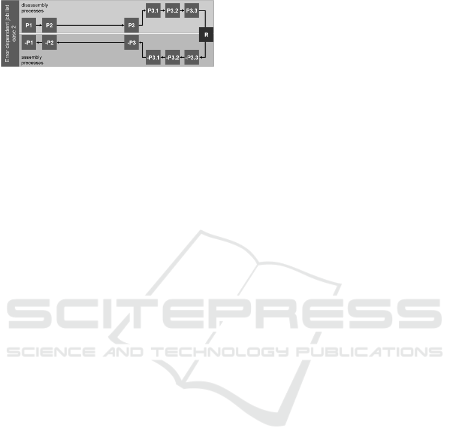
Figure 5: Case 2: Upstream assemblies are not
disassembled, but taken out all in one.
However, during the rework another reason of
failure can always be discovered than suggested.
Therefore, the worker assistance system has to allow
to switch the path to another part, if another reason is
assumed. When the rework job list is set, the control
system reads the first process and distributes the
machine data to the corresponding resource.
When the process is executed, it awaits a feedback
signal from the monitoring resource. If the feedback
is positive, the process data are stored for
documentation purposes and the next process can be
executed. However, the worker has the possibility to
choose another reason of failure. The control system
then calculates the path from the current position to
the new targeted position.
The combination and connection of planning and
control system allows to generate new rework jobs
based on defined reference products and processes,
also new paths during rework. This and the
description of process parameters beforehand make a
dynamical system possible, without modelling every
single rework job and product variant with their
processes.
4.3 Worker Assistance System to
Support Worker during the
Rework Job
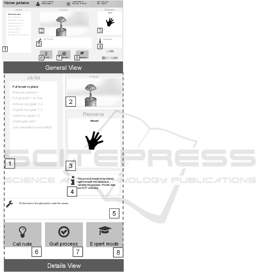
The worker guidance in form of a user interface (UI)
is the access point for the worker to interact with the
assistance system. The UI presents data similar to
(Aehnelt and Bader, 2015) considering the process,
the product as well as the resources. The data are
human readable as shown in Figure 6. The processes
are listed on the left side (1) and are ticked green by
the system whenever they are finished according to
plan. In the same list, the next process is already
highlighted and hints to the task to be carried out next.
The current process execution is presented by a
picture or an animation (2) based on the product data.
This visualization helps the worker to find the right
assembly place at the product. Especially for
beginners or less experienced workers, an animation
is helpful to find the right mounting place on the
product. Another advantage is that a picture can be
easily created from given a CAD (Computer-aided
design) model. On the right side of the UI,
information considering the resource to be used (3) is
provided. Beneath the resource information there is
an extra field for additional background information
considering the process or certain product (4). Its
purpose is to explain why certain processes need to be
done to develop awareness and avoid attempts
passing processes, due to the lack of knowledge.
Beneath the product part, there is a detailed
explanation of the process in case that the worker
does not know the process at all (5). At the bottom,
there are three buttons placed. The first button allows
the worker to demand more information considering
the current process (6). The second one quits the
process manually (7). Manual process quitting is
shown in the process list by an orange tick beside the
process. The third button allows the user to toggle
between expert and beginner mode (8). The purpose
of these modes is to provide beginners and
inexperienced worker with sufficient information but
avoiding annoying experienced worker with an
information overflow. This mode is designed for
beginners as well as trainings and qualification for
certain variants. Moreover, if an experienced worker
needs more information for just one process, he
always has the option to do so. The UI is implemented
as a web application and can be used platform
independent. Being an important part, the UI is
considered a resource and a part of the worker
assistance system. A further visualization system is
the laser projector (1 in Figure 2) which can be used
to show the exact order of bolt tightening processes
or highlighting a component which has to be handled
or dis/assembled.
In the current state of the work station setup, the
process checking/ validation is done by two different
systems. First of all, there is a 2D camera (2 in Figure
2) which will only check if the live captured image
matches the reference image. In case it does, the
process is triggered as correctly carried out. This kind
of checking is only applicable if the monitored
product property is limited to a completeness control.
The 2D camera can be replaced by 3D cameras to
ensure that an element is placed correctly e.g.
regarding the depth. Since the image evaluation
technology is processing intensive, it is mostly
reduced to a small area and is not suitable for every
assembly process. Since reference images mean that
appropriate processes need to be recorded once, an
alternative can be to generate the reference data from
CAD to avoid media disruption. Other technologies
involve camera technology (C) too, but reduce the
range of processed wavelength. In this case e.g. only
Intelligent and Flexible Worker Assistance Systems - Assembly Assistance Platform for Planning Assisted Assembly and Rework as Well as
Execution of a Worker-Centered Assistance
83
infrared LEDs can be detected and used to determine
the position and orientation of an IR-LED afflicted
object.
Figure 6: Worker guidance to lead the worker through the
assembly and allow him to interact with the worker
assembly system.
5 CONCLUSIONS AND
OUTLOOK
This paper describes the development of a human
centred assembly assistance platform which allows to
design and configure the worker assistance system.
To configure the worker assistance system and setup
the job list with less programming knowledge, a
planning environment for assembly planning
engineers is developed. In this environment,
information about parts, processes and resources are
linked with each other to create the maximum job list
for rework. Depending on an error code the job list is
dynamically modified by the control system. For the
modification and reduction of the maximum job list,
a specific rework process is added which describes
the repair work to be executed. The information of the
job list is processed by a worker guidance system to
provide human readable information to the worker.
The worker assistance system is equipped with
resources to document process results like cameras
and EC-driver. Moreover, the worker assistance
system allows short termed change of rework jobs as
well as different stages of disassembly, if the worker
detects unexpected failures.
For the planning environment, a concept exists
which will be implemented as a software solution in
the near future. On the worker assistance system side,
development considering the process evaluation are
still ongoing and concentrated on the development of
a 3D camera based completeness checking. This shall
improve the reliability of recognition and allow easy
creation of reference data by using CAD models,
which can configure any rework station.
ACKNOWLEDGEMENTS
This paper was written in the framework of the
research project NeWiP which is funded by the
German Federal Ministry of Education and Research
(BMBF) and supervised by the lead partner PTKA-
Karlsruher Institut für Technologie under the funding
code 02P14B203.
REFERENCES
Aehnelt, M., Bader, S., 2015. Information assistance for
smart assembly stations, Scitepress.
Aehnelt, M., Urban, B., 2015. In The Knowledge Gap:
Providing Situation-Aware Information Assistance on
the Shop Floor, Second International Conference,
HCIB 2015, Springer.
HUCAPP 2018 - International Conference on Human Computer Interaction Theory and Applications
84

Botthoff, A., 2015, Hartmann, E. A., Zukunft der Arbeit in
Industrie4.0, Springer Vieweg, Berlin.
Friedmann, M., Trapp, T. U., Stoldt, J., Langer, T., Putz,
M., 2016. A Framework for Information-driven
Manufacturing, 49th CIRP Conference on
Manufacturing Systems.
Hinrichsen, S., Riediger, D., Unrau, A., Assistance Systems
in Manual Assembly In Direct Digital Manufacturing in
the Context of Industry 4.0, Volume 01/2016, p. 3 - 14.
Lusic, M., Fischer, C., 2015. Worker information systems:
state of the art and guideline for selection under
consideration of company specific boundary
conditions, 48th CIRP Conference on manufacturing
systems - CIRP CMS 2015.
Lusic, M., Fischer, C., 2016. Static versus dynamic
provision of worker information in manual assembly: a
comparative study using eye tracking to investigate the
impact on productivity and added value based on
industrial case examples In 49
th
CIRP Conference on
Manufacturing Systems- CIRP CMS 2016.
Mueller, R., Hoerauf, L., Vette, M., Speicher, C., 2016a,
Planning and developing cyber-physical assembly
systems by connecting virtual and real worlds, Cirp
2016.
Mueller, R., Vette, M., Scholer, M., and Ball, J., 2016b,
Assembly Assistance and Position Data Feedback by
Means of Projection Lasers, SAE Technical Paper.
Weidner, R., Redlich, T., Wulfsberg, J.P., 2015, Technische
Unterstützungssysteme, Springer Vieweg, Heidelberg.
Wiesbeck, M., 2014, Struktur zur Repräsentation von
Montagesequenzen für die situationsorientierte
Werkerführung, Herbert Utz Verlag, München.
Intelligent and Flexible Worker Assistance Systems - Assembly Assistance Platform for Planning Assisted Assembly and Rework as Well as
Execution of a Worker-Centered Assistance
85
