
A Hybrid Feedback Control Model
for a Gesture-based Pointing Interface System
Kazuaki Kondo, Genki Mizuno and Yuichi Nakamura
Academic Center for Computing and Media Studies, Kyoto University, Yoshida Honmachi, Kyoto, Japan
Keywords:
Human-in-the-loop System, Pointing Behavior, Feedback Control Theory.
Abstract:
This study proposes a mathematical model of a pointing interface system that includes indicator behaviors
and pointer visualization based on the measurement of pointing postures. The key idea for simulating point-
ing behaviors under measurement noise involves constructing a hybrid feedback control model. It switches a
target value follow-up phase to a noise compensate phase at a specific elapsed time. We evaluated its perfor-
mance in terms of a simulation error with given step inputs as target values and random-walk noise sequences.
The results indicate that the proposed hybrid model simulates the actual pointing trajectories within several
centimeter errors.
1 INTRODUCTION
In daily communication, “pointing pose” is typically
used as an intuitive way to indicate target objects, lo-
cations, directions, and areas. However, the point-
ing pose could be potentially ambiguous for audience
such as when a questioner at a distance from a wide
screen points out a specific location on it. In these
type of cases, a pointing stick or a laser pointer is gen-
erally used to clearly indicate the target. The purpose
of our study is constructing a pointing support inter-
face as opposed to the additional equipments. Figure
1 illustrates an example of a construction that uses
visual sensing. It recognizes an indicator’s pointing
posture, estimates a target location on the screen, and
shows a visual pointer at the estimated location.
This study proposes a mathematical model of the
pointing interface system based on feedback control
theory including sensors, computers, visual devices,
and an indicator. It allow us simulation-based per-
formance evaluation and interface design. Once a
mathematical model of a target pointing interface sys-
tem is established, its behaviors under various point-
ing situations can be simulated and then its usability
is also evaluated. It aids in designing the interface
by employing a trial-and-error strategy without any
experimental evaluations in the real world. This ad-
vantage is extremely important for human inclusive
system because many real evaluations with partici-
pants require immense effort and involve difficulties
in configuring the same experimental conditions. Fur-
thermore, repeatability of human behavior is not very
high, and thus each participant must constantly repeat
pointing under the same conditions to collect a suffi-
cient number of samples from which general and es-
sential analysis/evaluations are obtained.
A key idea for modeling involves assuming that an
indicator switches a pointing strategy from approach-
ing to the target location to attempting to maintain a
pointer in its neighborhood. These behaviors are for-
mulated with two feedback control phases, namely a
target value follow-up phase and a noise compensate
phase. The characteristics of the two phases are rep-
resented with different parameter sets in the same for-
mulation with an assumption that the essential body
control schemes in those phases are same. This type
of hybrid framework is a first trial in modeling point-
ing interface systems that were investigated. Thus in
this paper, we evaluate the performance of the pro-
posed model in accuracy of pointing trajectory simu-
lation.
2 RELATED WORKS
Easy-to-use interfaces should suit human perception
and behaviors. Specifically, transient behaviors from
the beginning to end of pointing were analyzed by
several extant studies. Woodworth et. al. proposed
a pointing action model by using a combination of
feed-forward motions for a rapid approach to a tar-
get position, and subsequent feedback adjustments
Kondo K., Mizuno G. and Nakamura Y.
A Hybrid Feedback Control Model for a Gesture-based Pointing Interface System.
DOI: 10.5220/0006506501340141
In Proceedings of the International Conference on Computer-Human Interaction Research and Applications (CHIRA 2017), pages 134-141
ISBN: 978-989-758-267-7
Copyright
c
2017 by SCITEPRESS – Science and Technology Publications, Lda. All rights reserved

Indicator
Audience
Visual sensing
Visualization
Figure 1: An overview of a vision-based pointing interface.
The vision sensor measures indicator’s pointing posture and
estimates the indicated location to show a pointer.
(R.S.Woodworth, 1899). Fitts et. al. reported that
pointing duration depends on a distance and a tar-
get size(Fitts, 1954). This fact is known as “Fitts’s
law”, which has been used in many studies because
of its accurate approximation in various conditions.
McGuffin and Balakrishnan proposed zooming the re-
gion around a pointer (McGuffin and Balakrishnan,
2005). This gives a perceptual illusion that the tar-
get size and its distance from a pointer appear larger
than the actual amounts in neighborhood of a destina-
tion. In order to obtain a similar effect, several pre-
vious studies also controlled pointer size and/or its
speed (Worden et al., 1997; Grossman and Balakr-
ishnan, 2005; Blanch et al., 2004). However, those
conventional methods were designed for mouse inter-
faces and visualization on laptop monitors. Hence,
it is necessary to apply those scheme with respect to
the design of gesture-based pointing interfaces for a
distant and/or large screen.
A particular problem of the present gesture-based
pointing interface system is difficulty in estimating
the location that an indicator wants to point. One rea-
son is accuracy of pointing pose measurement. In
the pointing interface system, significant measure-
ment accuracy is required especially for a target at
a distance from an indicator because even extremely
small errors on body coordinates are amplified on a
screen. Although various type of motion capture tech-
niques developed with acceleration sensors (Slyper
and Hodgins, 2008), magnetic sensors (O’Brien et al.,
2000), or visual markers (Loper et al., 2014) could
satisfy the accuracy requirement, they are not appro-
priate in daily pointing situations. Several previous
studies proposed markerless methods based on visual
sensing that do not interfere with an indicator’s be-
havior (Shotton et al., 2011; Yoshimoto and Naka-
mura, 2015; Nickel and Stiefelhagen, 2003). How-
ever the performance of these methods does not sat-
isfy the requirement because visual sensing basically
corresponds to semi-2D measurement, and thus it is
weak in terms of self-occlusion and non-rigid defor-
mation by clothing.
Another problem in estimating pointed position is
body pose ambiguity. It corresponds to inconsistency
between 3D pose structure and a pointed location in
indicator’s intent. Although previous studies investi-
gated the relationship between a pointing posture and
an indicated position, it still be uncertain and influ-
enced substantially by pointing conditions. Addition-
ally each person possesses individual characteristics
in a pointing pose. Initially, Fukumoto et. al. re-
ported that a target position is placed on an indicat-
ing vector defined by a fingertip and a reference point
inside an indicator’s body (Fukumoto et al., 1994).
The reference point moves according to the pointing
pose. It is placed on an eye position when an indica-
tor’s arm is straight while resting on an elbow when
it is bent. Kondo et. al. reported on selecting a suit-
able model for intermediate poses with slightly bent
elbows (Kondo et al., 2016). Ueno et. al. indicated
that despite a straight arm, an intended location does
not stay on the indication vector. Although calibrating
the amount of the disparity as horizontal and vertical
offsets for targets at various locations (Ueno et al.,
2014), they did not propose its general model.
Extant studies do not discuss the mathematical
model that assumes estimation errors on pointed loca-
tions caused by the above problems. Although Kondo
et. al. proposed a feedback control model for point-
ing interface system (Kondo et al., 2015), it focused
on pure step responses under no or sufficiently small
noises.
3 CONTROL MODEL OF
POINTING INTERFACE
SYSTEM
3.1 Fundamental Formulation
With a vision-based pointing interface system as
shwon in Fig. 1, a pointing procedure is modeled as
a feedback loop as shown in Fig. 2. Based on classi-
cal control theory, Kondo et. al. formulated it with
four transfer functions H
g
, H
p
, H
s
and H
v
to denote
indicator’s body dynamics, visual perception catch-
ing a pointer location, computer estimating pointed
position, and visualization filter, respectively (Kondo
et al., 2015). However they did not consider the esti-
mation error caused by the visual sensing accuracy
and the pointing posture ambiguity. Our study as-
sumes that H
s
correctly estimates the pointed position

Indicator’s
pointing
gesture H
g
Visual
sensing H
s
Visualizatio
n H
v
Indicator’s
visual
perception H
p
Target
position p
t
-
+
Estimated
position p
e
Visualized
position p
c
Perceived
position p
r
Estimation error d
s
Figure 2: The feedback loop scheme of the vision-based
pointing interface system. The modules H
g
, H
p
, H
s
, and
H
v
describe the indicator’s body dynamics, visual percep-
tion, estimation of the pointing location, and pointer visu-
alization. Additionally d
s
refers to disturbance given to the
pointed position estimation.
and its estimation error is inserted as unexpected in-
coming noise d
s
. Additionally no visualization filter
is assumed to model a simple pointing interface sys-
tem. Therefore the transfer functions H
s
and H
v
con-
sisting of the pointing interface side are formulated as
follows :
H
s
(s) = e
−τ
s
s
H
v
(s) = e
−τ
v
s
(1)
where τ
s
and τ
v
denote the latencies for the pointed
position estimation, and the pointer visualization, re-
spectively.
The pointing dynamics H
g
is assumed as a second-
order lag element
H
g
(s) = e
−τ
g
s
K
g
T
2
g
s
2
+ 2ζT
g
s+ 1
. (2)
based on the preliminary analysis of pure step re-
sponses, where τ
g
denotes the dead time to begin a
pointing action. The human visual perception H
p
is
simply formulated as a first-order lag element
H
p
(s) =
K
p
T
p
s+ 1
(3)
to simulate a cognitive delay.
3.2 Hybrid Feedback Model
Let the output of H
s
be a control value denoted as p
s
,
because an indicator can not know amount of incom-
ing noise and thus tries to make p
s
closer to p
t
.
Given four transfer functions and input signals
p
t
(t),d
s
(t), the control value p
s
consists of two terms
of a target value response and a noise response:
P
s
(s) = P
t
(s)G
st
(s) + D
s
(s)G
sd
(s) (4)
with an assumption of their linear independency.
P
s
(s), P
t
(s), and D
s
(s) correspond frequency domain
descriptions of p
s
(t), p
t
(t), d
s
(t), respectively, with
Laplace transform. G
st
(s) and G
sd
(s) are described
as
G
st
(s) =
H
g
(s)H
s
(s)
1+H
g
(s)H
s
(s)H
v
(s)H
p
(s)
G
sd
(s) = −
H
g
(s)H
s
(s)H
v
(s)H
p
(s)
1+H
g
(s)H
s
(s)H
v
(s)H
p
(s)
.
(5)
based on a closed loop theorem.
Pointing behaviors is also influenced by values
of the parameters K
g
, T
g
, T
p
, ζ, τ
s
, τ
v
and τ
g
. These
should be configured so that Eq. (4) well simulate
actual pointing behaviors. We have an important con-
straint for the parameter configuration. With enough
small or ignorable noise, a trajectory of pointed po-
sitions generally converges to a target position after
sufficient time goes. Additionally p
t
can be given
as a step signal because an indicator usually config-
ures a target position at a distant from the initial po-
sition and it remains for a certain duration. Thus the
convergence behavior corresponds to a mathematical
constraint that stationary error e(t) = p
t
(t) − p
s
(t) at
t = inf must be 0 under the condition of p
t
(t) being a
step signal and d
s
= 0. This can be formulated as
p
s
(t)
p
t
(t)
|
t= ∞
= lim
s→0
s·
1
s
G
st
(s) = 1 (6)
based on the final-value theorem. It results in
K
p
=
K
g
− 1
K
g
(7)
where K
g
corresponds to the gain of H
g
. Here K
g
should not be extremely high when considering hu-
man body dynamics. Specifically, the previous study
reported that estimated values of K
g
are slightly ex-
ceed 1 (Kondo et al., 2015). This fact and Eq. (7)
lead to a significantly small feedback gain K
p
. Thus a
feedback effect to compensate noise influence is also
small. Essentially, it is difficult for a simple feedback
model to simultaneously satisfy precise tracking to a
target value and compensating noise influence. Thus
a more advanced scheme is necessary to construct a
compatible model.
In order to solve this issue, this study focuses
on a transition of control strategy as reported in
(R.S.Woodworth, 1899) ; namely human pointing be-
havior switches from a rapid approach at the begin-
ning to a subsequent adjustment. Similarly the pro-
posed model switches the control model from a target
value follow-up phase to a noise compensation phase
at a specific time T. Given this hybrid framework, the
control value p
s
(t) is formulated as
L
−1
(P
t
(s)G
st
(s)) t < T
L
−1
(P
t
(s)G
st
(s))|
t= T
+ L
−1
(D
s
(s)G
sd
(s)) t ≥ T
(8)

and the control strategy G
st
(s) for a target value
input and G
sd
(s) for an incoming noise sig-
nal are obtained from the same feedback scheme
shown in Fig. 2 but with individual pa-
rameter sets φ
t
= [K
t
g
, T
t
g
, T
t
p
, ζ
t
, τ
s
, τ
v
, τ
t
g
], φ
d
=
[K
d
g
, K
d
p
, T
d
g
, T
d
p
, ζ
d
, τ
s
, τ
v
, τ
d
g
], respectively. Because
even the different pointing strategy appears to follow
the same body control scheme and visual perception
rule. K
t
p
is automatically determined from the values
of K
t
g
by using Eq. (7) while it is not applied to φ
d
.
The reason is that the incoming noise is a probabilis-
tic sequence and thus it is less meaningful to discuss
convergence to that. τ
s
and τ
v
are assumed as com-
mon because the parameters of artificial components
do not depend on the human pointing strategy.
4 EXPERIMENTS
4.1 System Implementation
A pointing interface system was implemented as
shown in Fig. 3 for experimental evaluation of the
proposed method. The 1280pixel × 800pixel visual
contents are projected on a screen (white wall in
the figure) approximately corresponding to 2m × 1m
by using a short focal length projector RICOH PJ
WX4141. Subjects stand at a distance of approxi-
mately 2.5m from the screen. For natural pointing,
a contactless visual sensing should be used. A Kinect
v2 sensor is placed close to the screen at the left of the
subjects. However in the following experiments, the
magnetic field-based 3D pose sensor POLHEMUS
Liberty is used to accurately measure pointing pos-
tures. The magnetic sensors are attached on finger
tips of subject’s right hands and temples. Although
this implementation is not allowed in practical use, it
can be accepted for analyzing human pointing behav-
iors.
The subjects are requested to straighten their arms
during pointing behaviors. Therefore the indicated lo-
cation is estimated as where the indicating vector that
connects the center of the temples coordinates and the
finger tip across to the screen, based on a previous re-
port (Fukumoto et al., 1994). This corresponds to the
processing of H
s
. Then an approximately 1cm circu-
lar pointer that is assumed as a “point” for the subjects
is drawn at the estimated position on the screen.
4.2 Model Calibration
It is necessary to determine the parameters used in
each pointing phase prior to evaluating performance
Kinect sensor
Screen for display
Magnetic field-based
3D sensor
Figure 3: The experimental environment.
of the proposed model. In order to simplify a cali-
bration, we assumed that both of the parameter sets
φ
t
and φ
d
are independent for each other and do not
change. It allows to individually calibrate them be-
forehand.
The latency parameters τ
s
and τ
v
included in
H
s
, H
v
, respectively, are assumed as inherent and sta-
ble features. Thus they are estimated in advance from
directly measured durations of sensing, calculation
and display. The remaining parameters are estimated
via a non-linear optimization that minimizes residuals
between
ˆ
p
s
(t) from the model and the actually mea-
sured p
s
(t).
4.2.1 Target Value Follow-up Phase
A step input signal and its response are used to cal-
ibrate G
st
that describes the target follow-up phase.
They correspond to the pointing target that suddenly
arises at a distance from the initial location and the
transient trajectory till an indicator complete pointing
the target, respectively. Given this consideration, the
experimental procedures for step response measure-
ment are configured as follows.
1. The measurement starts when a subject indicates
an initial target visualized on the screen and the
pointer remains in that location.
2. The initial target suddenly disappears. Simultane-
ously, a new target pops up at a distance of ap-
proximately 70 cm from the initial target. The
subject changes his or her posture to move the
pointer onto the new target.
3. The measurement stops when the subject calls the
finish of the pointing action.
A sufficiently small noise d
s
(t) = 0 was expected be-
cause of the measurement accuracy of the magnetic
sensor and the straight arm condition. Thus it was as-
sumed the estimated values of pointed positions cor-
responded to p
s
(t). The subjects include three univer-
time(sec)
0 1 2 3
response(cm)
0
20
40
60
80
100
time(sec)
0 1 2 3
response(cm)
0
20
40
60
80
100
time(sec)
0 1 2 3
response(cm)
0
20
40
60
80
100
Subject #1 Subject #2 Subject #3
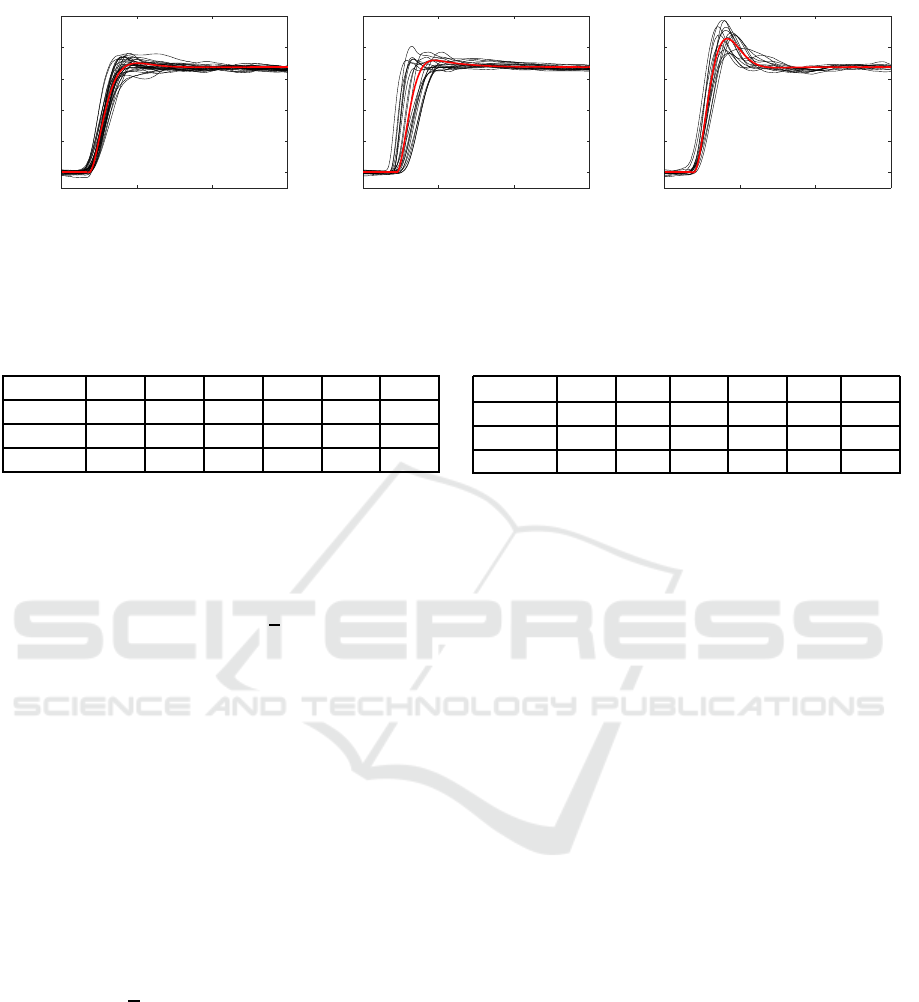
Figure 4: The calibration results of G
st
. The horizontal and vertical axes denote the elapsed time from when the new pointing
target appears and the distance from the initial location, respectively. (black) the measured step response trajectories. (red)
the trajectories simulated by G
st
with the optimized parameter sets φ
t
shown in Table 1.
Table 1: The optimized parameter set φ
t
for each subject.
Subject K
t
g
τ
t
g
T
t
p
K
t
p
T
t
g
ζ
t
#1 1.02 0.37 0.12 0.02 0.12 0.81
#2 1.04 0.45 0.36 0.03 0.10 0.79
#3 1.08 0.39 0.26 0.07 0.12 0.49
sity students. Each of them conducted N = 20 trials
under the same conditions.
The parameter optimization for the calibration is
formulated as
ˆ
φ
t
= argmin
∑
t
p
s
(t) − L
−1
1
s
G
st
(s, φ
t
)
2
(9)
that means minimizing sum of squared errors with re-
gard to the response trajectory. A trust region non-
linear optimization method is applied to solve Eq. (9).
The upper and lower limits of the parameters were
configured as 1 < K
g
≤ 2, 1 ≤ T
g
≤ 10
4
, 0 < ζ ≤ 50,
300 ≤ τ
g
≤ 700, 0 ≤ T
p
≤ 10
4
by considering of hu-
man body dynamics and visual perception. The opti-
mal parameter set that minimizes Eq. (9) is selected
from the results of multiple optimizations beginning
with various initial values so that at least few of them
reached the global minimum. With this procedure, an
optimal parameter set φ
t
(i, j) for each pointing trial
i of each subject j is determined. After that, the fi-
nal parameter set for each subject is estimated as their
average values
1
N
∑
i
φ
t
(i, j). A direct optimization of
the common parameter set for all trials is simpler than
the above two step calibration. However it estimates a
parameter set that averages dispersed pointing trajec-
tories in a real domain but not in a frequency domain.
The two step calibration averages the parameter sets
that reflect the system behaviors in both the real and
frequency domains, and thus it appears to maintain
essential characteristics.
The black and red curves in each figures in Fig. 4
show the trajectories of each subject’s 20 pointing tri-
als and their simulated trajectories with the calibrated
Table 2: The optimized parameter set φ
d
for each subject.
Subject K
d
g
τ
d
g
T
d
p
K
d
p
T
d
g
ζ
d
#1 1.73 400 14.5 1.69 317 3.22
#2 1.73 403 18.3 1.63 296 14.2
#3 1.73 403 14.2 1.69 288 2.32
parameter sets as shown in Table 1, respectively. Even
the 20 samples under the same experimental condition
had certain diversity because of unconscious pointing
posture perturbation. The calibrated models approxi-
mated almost the center of the diversities. The amount
of the diversity depends on the subject. The pointing
trajectories of subjects #1 and #3 appear to be ade-
quately simulated while those of subject #2 are not so
much.
4.2.2 Noise Compensation Phase
Similarly the parameter set φ
d
of G
sd
for the noise
compensation phase is estimated by using the pointer
location stabilizing behaviors against to given noises.
The experimental procedures for the measurement are
configured as follows :
1. The measurement begins when a subject indicates
a stable target visualized on the screen and the
pointer stays at that location.
2. A noise sequence is added to the measured point-
ing location p
s
(t). The subject changes its own
pointing posture to maintain the pointer on the sta-
ble target.
3. The measurement stops after a certain experimen-
tal duration T
d
= 4.0 seconds.
The pointing target does not move, and thus only the
responses to given noises are appeared. A vision-
based pose measurement usually searches a neighbor-
hood of that in the previous frame. It corresponds to
that the estimation error is accumulated. Thus in this
experiment a random walk sequence is assumed as the
given noise. It is formulated as
time(sec)
0 1 2 3 4
response(cm)
-20
-10
0
10
time(sec)
0 1 2 3 4
response(cm)
-20
-10
0
10
time(sec)
0 1 2 3 4
response(cm)
-20
-10
0
10
time(sec)
0 1 2 3 4
response(cm)
-20
-10
0
10
time(sec)
0 1 2 3 4
response(cm)
-20
-10
0
10
time(sec)
0 1 2 3 4
response(cm)
-20
-10
0
10
Subject #1 Subject #2 Subject #3
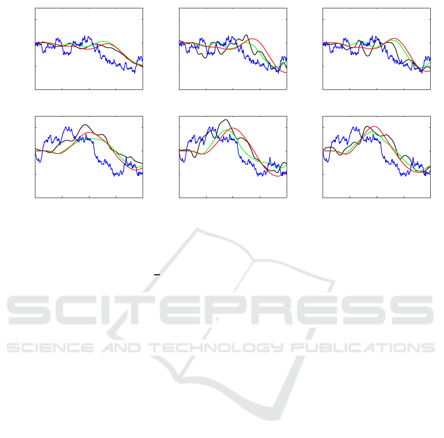
Figure 5: The calibration results of G
sd
. The figures in each column correspond to results with respect to two representative
trials of each subject. (blue) given random-walk noise sequences. (black) the measured noise compensation trajectories.
(green) the trajectories simulated by G
sd
with the optimized parameter sets φ
d
(i, j) for each pointing trial i and subject j. (red)
those with the final parameter sets φ
d
(j) =
1
N
∑
i
φ
t
(i, j) shown in Table 2.
n
r
(t + 1) = n
r
(t) + sx, x ∼ N (0, 1) (10)
with an update factor x that follows an indepen-
dent and identical standard normal distribution where
n
r
(0) = 0, t < T
d
, and s = 2.0 cm were configured. In
the experiment, 20 different random walk sequences
{n
r
(t)} were given to each subject. The manner to ac-
quire an optimal parameter set is the same as that in
the previous calibration experiment.
Figure 5 shows the calibration results of each sub-
ject. The blue, black, green, and red curves in the fig-
ures denote the given random-walk noises, response
trajectories, simulated trajectories with the individu-
ally optimized parameter sets for each trial, and those
with the final parameter sets as the results of the two
step estimation, respectively. A high frequency com-
ponent filtering with particular latency appears in a
translation from the given noise trajectories to their
responses. Simultaneously we can see that small dis-
parities remain between the given noise sequences
and their compensation response. Our hypothesis is
that human pointing dynamics is not so fast to follow
high frequent changes. Thus too much trial to do so
may result in worse. In stead of that, the subjects ap-
peared to allow the certain amount of remaining gap
between the shown pointer and the target position.
This non-linear characteristic is a possible reason of
not so good approximation performance shown as the
inconsistency in the black and green (or red) curves in
Fig. 5.
While the proposed G
sd
roughly simulate the
noise responses, it does not adequately explain rel-
atively high frequent components. The proposed
model consists of a tamdemly connected 2nd-order
and 1st-order lag elements, and thus it is difficult to
explain the non-linear characteristics. A visual per-
ception component that is insensible to small position
disparities be necessary.
4.3 Model Evaluation
The performance of the proposed hybrid model was
evaluated in the situations such as when an indicator
attempts to move a pointer under a certain noise. A
method to evaluate is analyzing how it approximates
actual pointing trajectories.
In a manner similar to the calibration experiments,
p
t
(t) and d
s
(t) given to the subjects were config-
ured as step inputs and random-walk sequences. The
way to measure the response trajectories p
gt
s
(t) as
ground truth was almost same as that shown in sec-
tion 4.2.1 with the exception of random-walk noises
being added during pointing. Their simulated trajec-
tories p
prop
s
(t) were generated by the proposed hybrid
feedback model Eq. (8) by using G
st
, G
sd
calibrated
in the previous two experiments and the same p
t
(t)
and d
s
(t) given to the subjects. The model switch-
ing time T was manually configured to 1.2 seconds
(just after the overshoot in most cases). The reference
time(sec)
0 1 2 3 4
response(cm)
0
20
40
60
80
100
time(sec)
0 1 2 3 4
response(cm)
0
20
40
60
80
100
time(sec)
0 1 2 3 4
response(cm)
0
20
40
60
80
100
time(sec)
0 1 2 3 4
response(cm)
0
20
40
60
80
100
time(sec)
0 1 2 3 4
response(cm)
0
20
40
60
80
100
time(sec)
0 1 2 3 4
response(cm)
0
20
40
60
80
100
Subject #1 Subject #2 Subject #3
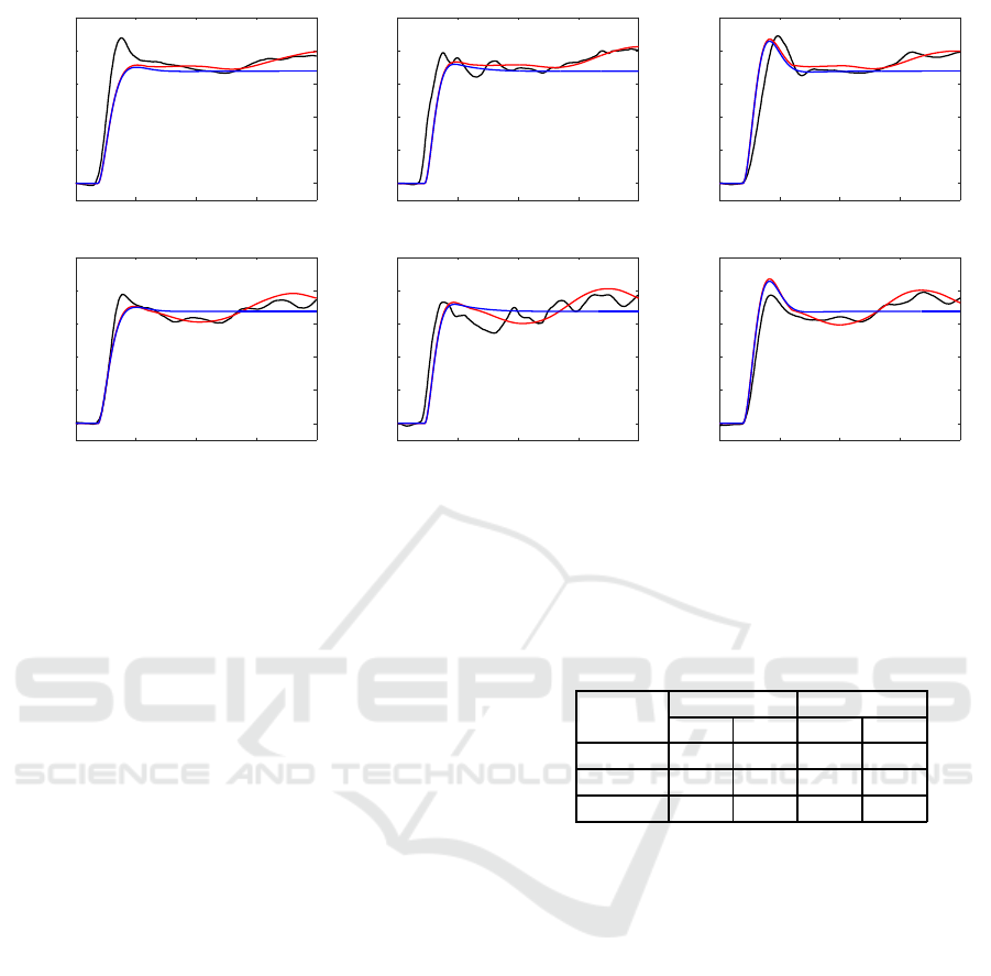
Figure 6: The predicted pointing trajectory by simulation. The figures in each column correspond to results with respect to two
representative trials of each subject. The given random-walk noise sequences are different from those used in the calibration
phase. (black) the ground-truth trajectories p
gt
s
(t). (red) the simulated trajectories p
prop
s
(t) by using the hybrid model. (blue)
those by using reference model.
trajectories p
ref
s
(t) for comparison were generated by
using the common parameter set φ
t
for both of G
st
and G
sd
. This assumed the conventional non-hybrid
model that does not consider the influence of the esti-
mation error.
The predction results by simulation of each sub-
ject are shown in Fig. 6. The proposed hybrid model
begins to compensate for the noise influence after
t = T, and thus the trajectories p
prop
s
(t) more ade-
quately approximate the ground truth p
gt
s
(t). How-
ever the fact that the noise compensation behaviors
can not be well approximated as shown in the calibra-
tion results appeared also in this evaluation situation.
Another reason for the remaining errors corresponds
to the influence of the phase switching time T. In this
moment, a method to determine T is a quite naive way
and it should be automatically configured based on
model parameters and input signals. Thus the influ-
ence of T appears to be approximated to the station-
ary bias. This indicates that the trajectories simply
go up or down in the time-location coordinate accord-
ing to T. A total comparison in statistic performance
of the simulation errors e
prop
(t) = p
prop
s
(t) − p
gt
s
(t),
e
ref
(t) = p
ref
s
(t) − p
gt
s
(t) are shown in Table 3. The
simulation accuracies of the proposed method are
within several centimeters. It is approximately half
of those with respect to the reference method.
The proposed hybrid model mainly focuses on
compensating noise influence at a stationary state be-
Table 3: The statistic values of the simulation accuracy
|e
prop
(t)| and |e
ref
(t)| (cm).
Subject
|e
prop
(t)| |e
ref
(t)|
ave. s. d. ave. s. d.
#1 3.87 4.05 8.12 5.74
#2 5.15 5.23 8.87 6.63
#3 4.29 3.99 8.01 5.92
cause it is expected that a little perturbation does not
exhibit a significant influence during a transient pe-
riod. However the simulation accuracy at t < T is
still not high. This confirmed that it is also necessary
to compensate for a relatively low amount of distur-
bance at the beginning of pointing. In actual pointing
situations, pointing often starts by holding indicator’s
hand hanged down. In this case, large amount of noise
may be caused even in a transient period. An indica-
tor does not attempt to cancel such type of large noise
and instead configure a new target value from the cur-
rent pointer location to the original target location.
5 CONCLUSION
This study involved proposing a mathematical model
of a pointing interface system to simulate its behav-
iors with respect to step signal targets and pointed po-
sition estimation errors. The proposed hybrid feed-
back control model switches its characteristics from a

target value follow-up phase to a noise compensation
phase. The simulation accuracy becames fairly higher
than that of the conventional non-hybrid model. Nev-
ertheless a large amount of simulation error at a tran-
sient period continues to constitute a considerable
problem.
In the experiments, a very simple pointing situa-
tion was assumed in which the subjects stand at the
same location, point with their arm being straight,
and start pointing from previous pointing postures.
The travel distance to the new target is also limited
to only 70 centimeters. The performance in more
various conditions must be evaluated. A further es-
sential issue of human behavior diversity requires a
more advanced framework. Additionally in order to
really contribute interface design, it is necessary to
apply and model various visualization methods such
as an area pointer, a blurred pointer, and showing it at
a smoothed location.
REFERENCES
Blanch, R., Guiard, Y., and Beaudouin-Lafon, M. (2004).
Semantic pointing: improving target acquisition with
control-display ratio adaptation. In Proceedings of the
SIGCHI Conference on Human Factors in Computing
Systems, CHI ’04, pages 519–526.
Fitts, P. M. (1954). The information capacity of the hu-
man motor system in controlling the amplitude of
movement. Journal of Experimental Psychology,
47(6):381–391.
Fukumoto, M., Suenaga, Y., and Mase, K. (1994). Finger-
Pointer: Pointing interface by image processing. Com-
puters & Graphics, 18(5):633–642.
Grossman, T. and Balakrishnan, R. (2005). The bubble cur-
sor: enhancing target acquisition by dynamic resiz-
ing of the cursor’s activation area. In In Proc. of the
SIGCHI conference on Human factors in computing
systems, pages 281–290. ACM.
Kondo, K., Mizuno, M., and Nakamura, Y. (2016). Analysis
of human pointing behavior in vision-based pointing
interface system - difference of two typical pointing
styles-. In In Proc. on The 13th IFAC/IFIP/IFORS/IEA
Symposium on Analysis, Design, and Evaluation of
Human-Machine Systems 2016.
Kondo, K., Nakamura, Y., Yasuzawa, K., Yoshimoto, H.,
and Koizumi, T. (2015). Human pointing modeling for
improving visual pointing system design. In In Proc.
of Int. Symp. on Socially and Technically Symbiotic
Systems (STSS) 2015.
Loper, M., Mahmood, N., and Black, M. J. (2014). Mosh:
Motion and shape capture from sparse markers. ACM
Transactions on Graphics, 33(6):220:1–220:13.
McGuffin, M. J. and Balakrishnan, R. (2005). Fitts’ law
and expanding targets: Experimental studies and de-
signs for user interfaces. ACM Trans. Comput.-Hum.
Interact., 12(4):388–422.
Nickel, K. and Stiefelhagen, R. (2003). Pointing gesture
recognition based on 3d-tracking of face, hands and
head orientation. In In Proc. of The IEEE Int. Conf.
on Multimodel Interfaces, pages 140–146.
O’Brien, J. F., Bodenheimer, R., Brostow, G., and Hodgins,
J. K. (2000). Automatic joint parameter estimation
from magnetic motion capture data. In Graphics In-
terface, pages 53–60.
R.S.Woodworth (1899). The accuracy of voluntary move-
ment. Phychological Review Monograph Sullplement,
3(13):1–119.
Shotton, J., Fitzgibbon, A., Cook, M., Sharp, T., Finocchio,
M., Moore, R., Kipman, A., and Blake, A. (2011).
Real-time human pose recognition in parts from sin-
gle depth images. In In Proc. of the 2011 IEEE Con-
ference on Computer Vision and Pattern Recognition,
CVPR ’11, pages 1297–1304.
Slyper, R. and Hodgins, J. K. (2008). Action capture with
accelerometers. In In Proc. of the 2008 ACM SIG-
GRAPH/Eurographics Symposium on Computer Ani-
mation, SCA ’08, pages 193–199.
Ueno, S., Naito, S., and Chen, T. (2014). An efficient
method for human pointing estimation for robot in-
teraction. In In Proc. of IEEE Int. Conf. on Image
Processing 2014, pages 1545–1549.
Worden, A., Walker, N., Bharat, K., and Hudson, S. (1997).
Making computers easier for older adults to use: area
cursors and sticky icons. In Proceedings of the ACM
SIGCHI Conference on Human factors in computing
systems, pages 266–271. ACM.
Yoshimoto, M. and Nakamura, Y. (2015). Cooperative ges-
ture recognition: Learning characteristics of classi-
fiers and navigating user to ideal situation. In In Proc.
of The 4th IEEE Int. Conf. on Pattern Recognition Ap-
plications and Methods, pages 210–218.
