
Personal Mobility with Assistive Walker
User Interface Design for Vehicle Mode
Masahiro Onozawa
1
, Sho Yokota
1
, Daisuke Chugo
2
and Hiroshi Hashimoto
3
1
Department of Mechanical Engineering, Toyo University, Kawagoe, Japan
2
School of Science and Technology, Kwansei Gakuin University, Sanda, Japan
3
Advanced Institute of Industrial Technology, Shinagawa, Japan
Keywords:
Personal Mobility, Assist, Walking, Electric Cart, Walker.
Abstract:
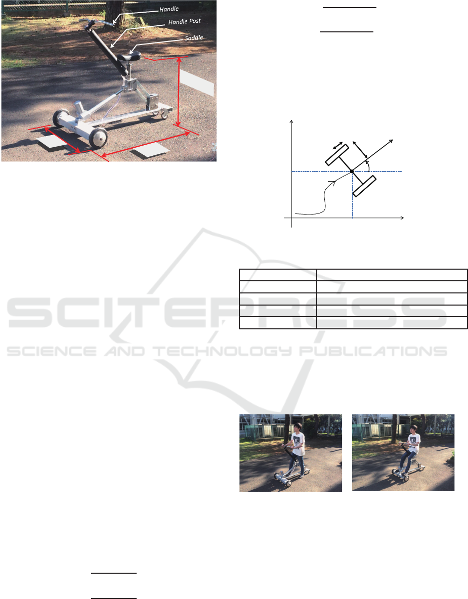
This paper presents Personal Mobility with assistive Walker (PM-W). PM-W is consists of handle, handle post,
position adjustable saddle, and two inwheel motors. The feature of PM-W is two mobile modes: ”walking
assist mode” and ”vehicle mode”. In ”walking assist mode”, PM-W assists user’s walking by driving two
wheels while user saddles on the seat and walks. In ”vehicle mode”, user controls PM-W like an electric bike
or conventional senior cart. Thus, a certain control interface is needed in ”vehicle mode”. Therefore, this
paper develops the interface for ”vehicle mode”. The proposed interface uses the bending strain at the root
of the handle post, because the handle should not have any moving parts on it such as throttle lever or stick
controller for supporting elderly’s stable posture. In order to verify the operability of this interface, the basic
experiment was conducted. From the results of the experiment, it is appropriate that the interface is adopted
for ”vehicle mode”, because it can be regarded that the operability of proposed interface is equal to or more
than the conventional interface.
1 INTRODUCTION
It is important to take a customary exercise for keep-
ing and promoting elderly’s health (Penedo, 2005). In
particular, the activities with going out leads to main-
tain both mental and physical health (Transportation
Research Board, 2005). However, there is the fact that
the weak of elderly’s physical ability makes the range
of activity narrow (Chou CH, 2012). Therefore, it is
desired that a certain support system expanding the
activity range with controlling the physical weakness.
There are some solutions for this problem. Honda
Walking Assist (Honda Motor Co., LTD., 2017) as-
sists to keep the user’s walking rhythm and stride
by power assisting for the swing of the legs while
measuring the hip joint movement. This system en-
ables user’s walking, however it requires pre-settings
or preparation for walking because this is the wear-
able power assists device. The other walking sup-
port system is the electric cart with pedaling unit (Jin-
hua She, 2013). The feature of the system is the pedal
unit which is the user interface of the electric cart,
which is one of the Personal Mobilities, and it is able
to control the load of it with adjusting user’s physi-
cal conditions. The rotational speed of the pedal is
used for controlling the velocity of the cart. User can
take exercise while moving by actuating the pedal.
In addition, this system adopts the electric cart be-
ing kinds of personal motilities. Thus it can expand
the activity range more than actual user physical abil-
ity, and can contribute to promote the activities with
going out. However, the exercise in this system is
different movement from natural human walking be-
cause it is only legs movements. It, therefore, is diffi-
cult to take whole body exercise like human walking.
And walking exercise is recommended for keeping el-
derlies health (American College of Sports Medicine,
2009).
On the other hand, the walker with a saddle
such as ”Raku-walk” (Kikuchi Seisakusho Co., LTD.,
2017), ”AR-5” (Ai Label Co., LTD., 2017) and
”KW200” (Kishi Engineering Co., LTD., 2017) have
been developed. These walkers do not use any ac-
tuators. The saddle in the walker partially supports
user’s weight, user can move forward by moving their
legs with sitting on it. Therefore it is expected to ex-
pand the user’s activities range with reducing phys-
ical load, because the leg strength is made full use
for moving forward not for supporting their weight.
However, it is difficult to realize natural walking, be-
Onozawa, M., Yokota, S., Chugo, D. and Hashimoto, H.
Personal Mobility with Assistive Walker - User Interface Design for Vehicle Mode.
DOI: 10.5220/0006474604650470
In Proceedings of the 14th International Conference on Informatics in Control, Automation and Robotics (ICINCO 2017) - Volume 2, pages 465-470
ISBN: Not Available
Copyright © 2017 by SCITEPRESS – Science and Technology Publications, Lda. All rights reserved
465
700
[mm]
690~780
1
200
Figure 1: Overview of the PM-W.
cause user’s pelvis leans during walking and sitting on
these walking apparatus. It is also difficult to make an
active power assist and remarkable expansion of ac-
tivity range, because they do not have any actuators.
For this problem, we think that the problem can
be solved by compensating each weak points in above
mentioned walker and electric cart by combining the
electric mobile function of PM and walker’s exercise
function. This research, therefore, proposes ”Per-
sonal mobility with assistive walker: PM-W” which
has two mobile modes being ”walking assist mods”
and ”vehicle mode”. Here, ”walking assist mode”
assists user’s walking exercise, and ”Vehicle mode”
offers driving electric cart experience for users. In
particular, this paper introduces the designed proto-
type of PM-W and studies the interface in the ”vehicle
mode”.
2 OVERVIEW OF PM-W
The prototype of PM-W is shown in Fig. 1. PM-
W is consists of handle, handle post, position ad-
justable saddle, and two inwheel motors. And PM-
W is conventional two wheeled system shown in Fig.
2. In this figure, W[m] means width of PM-W and
R[m] is radius of wheel. The control inputs of the
system are Velecity v
ref
[m/s] and angular velocity
ω
ref
[rad/s], and relationship between the wheel rota-
tional speeds ω
r
, ω
l
[rad/s] and control inputs are de-
signed by (1)(2).
v
ref
=
R(ω
l
+ ω
r
)
2
(1)
ω
ref
=
R(ω
r
− ω
l
)
2W
(2)
From (1) and (2), wheel speeds realizing v
ref
, ω
ref
are described as:
ω
r
=
v
ref
+ ω
ref
W
R
(3)
ω
l
=
v
ref
− ω
ref
W
R
. (4)
Thus, the role of the developed interface is to gen-
erate the control inputs v
ref
, ω
ref
from user’s con-
trol intention, and transmits these inputs to the servo
driver of PM-W. Here the specification of PM-W is
summarized in Table. 1.
x
y
W
R
x
y
ref
v
ω
ref
Figure 2: The coordinate system of the PM-W.
Table 1: Specifications of the PM-W.
Width 700 mm
Wheel Radius 4 inch
Weight capacity 80 kg
Actuator DC brushless motor (90W x 2)
Power source Ni-MH battery (22.2[V] 4.0[Ahr])
2.1 Two Mobile Modes
The feature of PM-W is that it has two mobile modes:
”walking assist mode” and ”vehicle mode” shown in
Fig. 3.
(a) Walking Assists mode
(b) Vehicle mode
Figure 3: Vehicle mode and Walking assist mode.
2.1.1 Walking Assist Mode
In ”walking assists mode”, the height of the saddle is
adjusted to the user’s hip position in an upright stance.
The saddle partially support user’s weight in the up-
right stance. User walks with grasping the handle. At
this time, the handle functions as a handrail to support
user posture not to fall down while walking. Here, the
relative position of the saddle and the footrest was de-
ICINCO 2017 - 14th International Conference on Informatics in Control, Automation and Robotics
466
designed so as not to inhibit natural user’s walking by
experimentally investigating the stride. Because there
is a possibility of collision between the footrest and
user’s foots, if the relative position between saddle
and footrest is not appropriately designed. In addi-
tion, the handle and handle post were rigidly mounted
on the body frame of PM-W without any moving
parts, because the handle is important part for user’s
safety for preventing from falling down. The system
control the motor speed and assists user’s walk with
adapting users movements. In addition, by adjusting
motor torque, the assists level can be adopted to user’s
physical ability. From the above, user can exercises
while he/she moves with meeting own physical abil-
ity.
2.1.2 Vehicle Mode
In the ”vehicle mode”, the saddle position is lowered,
and user completely sits on the saddle. Then user
places own foots on the front section of PW-W as
a foot rest. And user can move while two inwheel
motors are controlled by the developed interface. By
this mode, PM-W can be used as conventionalelectric
cart, therefore, user can move and easily expand own
activity range.
By switching above mentioned two mobile modes
appropriately, user can exercise with moving and can
expand own activity range.
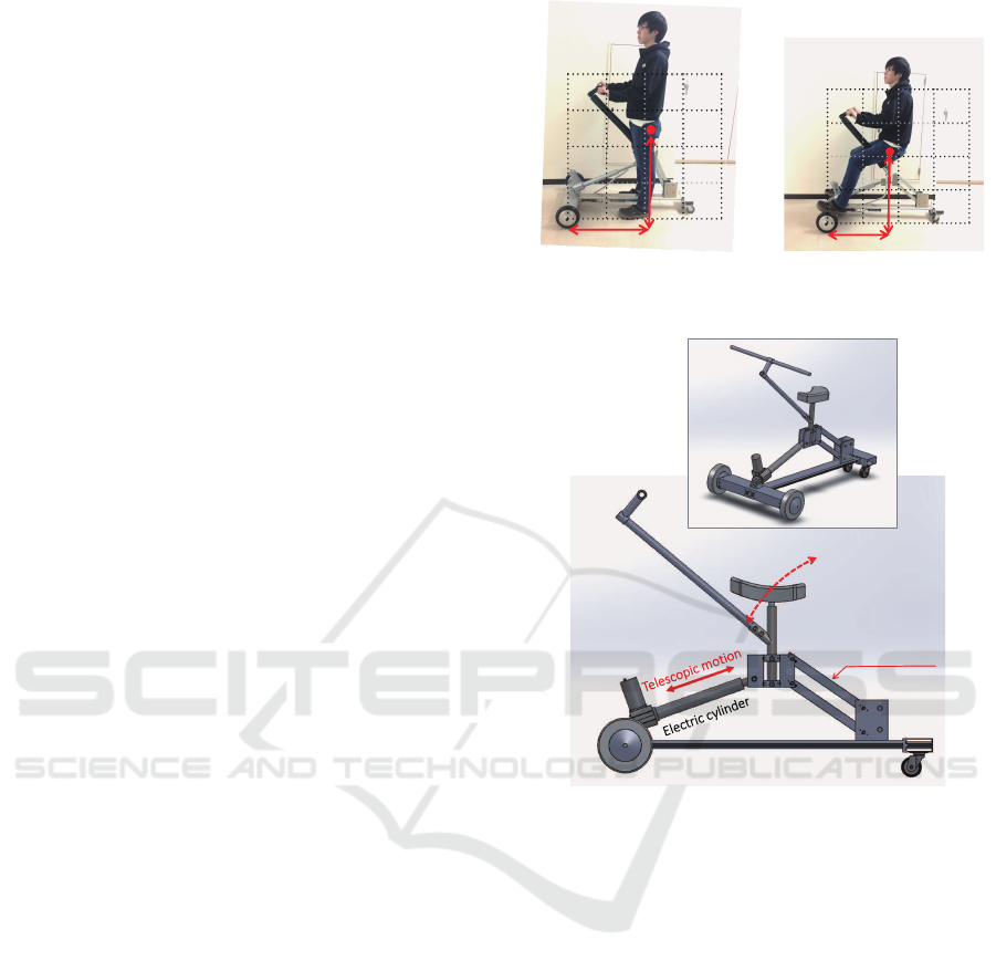
2.2 Lifting Saddle Mechanism
The height of the saddle is different in these two
modes. In the ”Walking assist mode”, the saddle po-
sition should be high and should have enough gap to
foot rest depicted in Fig. 4 to realize natural walk-
ing. On the other hand, in ”Vehicle mode”, the sad-
dle position should be low and close to foot rest. To
do so, the saddle needs not only lifting function but
also adjusting function in a back and forth position.
In order to realize this movement by one actuator, the
lifting and sliding mechanism using electric cylinder
and parallel links is adopted shown in Fig.6. Thanks
to this mechanism, the saddle can be adjusted in both
height and back/forth position by one actuator.
3 USER INTERFACE FOR
VEHICLE MODE
The general user interface represented by a stick con-
troller or a throttle lever has the mechanical moving
part, and user operates a machines by adjust its range.
High
Long
Figure 4: Saddle height at
Walking Assist mode.
Short
low
Figure 5: Saddle height at
Vehicle mode.
Parallel link
Trajectory of the saddle
Figure 6: Lifting saddle mechanism.
In our PM-W, the contacting point between user
and the machine is the handle. Therefore the han-
dle should also be utilized as the interface in ”vehicle
mode”. However, the handle is used as a handrail for
preventing from falling down or supporting elderlies
stable posture. Thus, the handle should not have the
moving part on it such as throttle lever or stick con-
troller.
3.1 Input Information to Interface
When user grasps the handle and adds forces on it,
the small strain occurs in the handle post (the handle
is shown in Fig. 1). This system adopts the strains
around the handle post as an interface inputs. By this
method, it will be possible to obtain user’s control in-
tention form the rigid part.
Personal Mobility with Assistive Walker - User Interface Design for Vehicle Mode
467
3.2 FEM at Post of Handle Bar
In order to realize the interface using strains, the at-
taching portion of strain gauges is studied by Finite
Element Method. The purpose of this FEM is as:
• Selection of the attaching part for controlling for-
ward and backward movement of PM-W
• Selection of the attaching part for steering control
of PM-W.
Here, there are two types of strain being bending and
twisting. It is natural to use the vertical bending strain
being generated when the user puts the handle in for-
ward and backward for controlling forward and back-
ward movements.
The candidates for steering control are following
two parts:
• The bending strain in left and right direction,
when user applies the forces on the handle in lat-
eral direction to realize steering control of PM-W
• The twisting strain, when user twists handle to re-
alize steering control of PM-W.
In these two strains, the part showing big strain is
preferable to be used for inputs to the interface even
if small forces are applied, because the resolution of
control forces from user becomes high. For this rea-
son, the part showing big strain is used for steering
control of PM-W.
FEM is conducted under following conditions: the
material handle post is aluminum A6063, the hollow
pipe (inner diameter 24mm, outer diameter 28mm).
the following three kinds of forces are applied to the
handle.
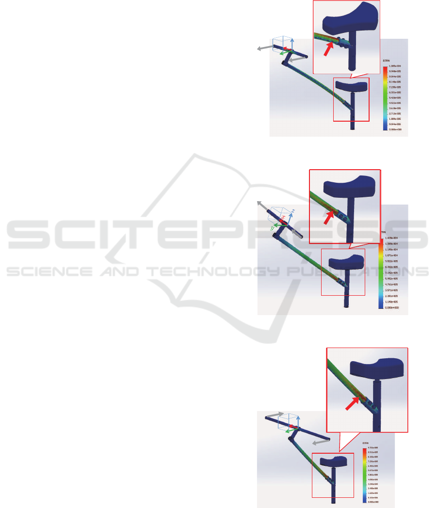
FEM1 The bending strain when the forces are ap-
plied to the both endpoints of handle parallel to y
axis in Fig. 7. ( forward / backward operation )
FEM2 The bending strain when the forces are ap-
plied to the both endpoints of handle parallel to x
axis in Fig. 8. ( Steering operation )
FEM3 The twistin strain when the forces are applied
to the both endpoints of handle parallel to y axis
in Fig. 9 in oposit direction each other. ( Steering
operation )
The result of FEM1 is shown in 7. From this fig-
ure, it is turned out that vertical bending strain is gen-
erated at root of handle post by applying forward /
backward forces to both endpoints of handle. Thus,
the vertical strain at the root of the handle post can be
used for forward / backward control of PM-W.
The result of FEM2 and FEM are shown in Fig.
8 and Fig. 9 respectively. Form these figures, it is
turned out that both bending and twisting strain are
generated at the root of the handle post. These strains
are summarized in Table 2. In this table, FEM2 shows
bigger strain than FEM3. From this thing, the hor-
izontal bending strain is more suitable than twisting
strain for the steering control of PM-W.
f
2
f
1
y
z
x
STRAIN
Figure 7: Bending strain at the root of handle post by for-
ward force on the handle.
f
2
f
1
STRAIN
Figure 8: Bending strain at the root of handle post by lateral
force on the handle.
f
2
f
1
z
x
STRAIN
Figure 9: Bending strain at the root of handle post by twist-
ing force on the handle.
ICINCO 2017 - 14th International Conference on Informatics in Control, Automation and Robotics
468
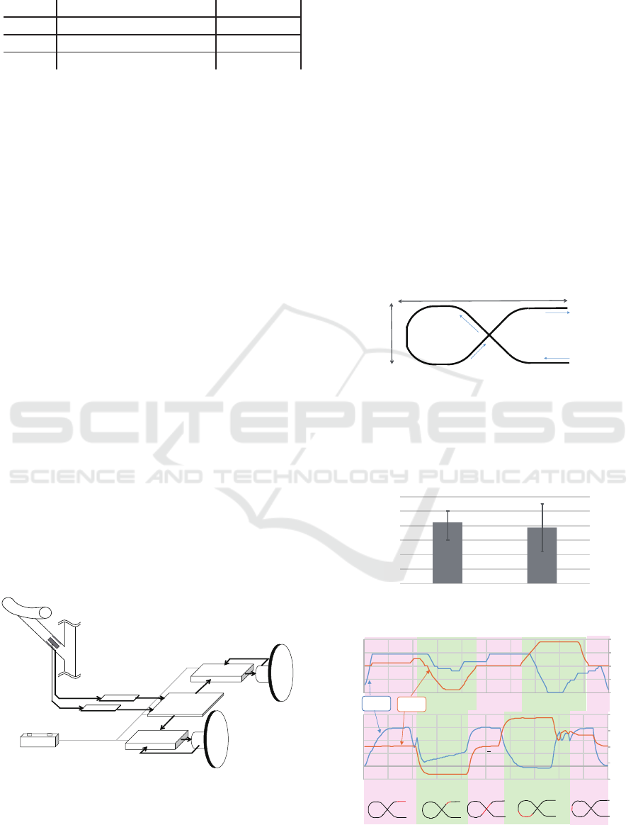
Table 2: Rsults of FEMs.
Drection of applied force Strain
FEM1 Forward 1.09× 19
−4
FEM2 Right 1.48× 19
−4
FEM3 Twisting Right 9.72× 19
−5
From the above, this system adopts the bending
strains in horizontal and vertical direction at the root
of handle post as the inputs for the interface in ”vehi-
cle mode”.
3.3 Sequence of the Control
The vertical bending strain is used for forward / back-
ward control. The horizontal bending strain is used
for steering control. Here, the vertical strain is ex-
pressed by ε
v
, and the horizontal strain is shown in
ε
ω
. The both initial strains are expressed by ε
v0
, ε
ω0
.
The control inputs v
ref
ω
ref
(1),(2) are generated based
on these strain as follows:
v
ref
ω
ref
=
a
1
0
0 a
2
ε
v
− ε
v0
ε
ω
− ε
ω0
(5)
Here, a
1
, a
2
are conversion coefficients from strain
to control inputs, and their values are set by cut & try.
The total system configuration including the interface
is shown in Fig. 10. The bending strains at the root
of the handle post are measured by the strain gauges,
and measured strains are amplified and are sent to the
Aruduino Mega. Aruduino Mega generates the con-
trol inputs v
ref
, ω
ref
by using (5), and calculates the
each motor speed ω
r
, ω
l
by using (3) and (4). The mo-
tor drivers (Hibot, 1BLDC PowerModule
c
) receives
ω
r
, ω
l
, and then the motors are driven and PM-W is
activated. The open loop control is adopted for mo-
tors.
Baery
Strain Gauge Amp.
( )
v
ε
Strain Gauge Amp.
( )
ω
ε
Arduino Mega
2560
Wheel (Le)
Brushless DC Motor
Motor driver
Motor driver
Strain
Gauges
Wheel (Right)
Brushless DC Motorω
ε
hall sensor
hall sensor
l
ω
r
ω
v
ε
Figure 10: System configuration of the mobile platform.
4 TEST RUN
In the ”Vehicle mode”, since the interface using mov-
ing parts cannot be used for user safety, this system
adopts the bending strains at the root of the handle
post. In order to verify the operability of this inter-
face, the basic experiment was conducted. In this
experiment, we prepared the stick controller as the
control to proposed interface. The stick controller is
widely used for electric wheelchair and man-machine
interface.
The subject operated PM-W by using two inter-
faces along with the course shown in Fig. 11. At
that time, the lap times by two interfaces were mea-
sured. If the lap time by the proposed interface would
be same as it by the stick controller, it could be said
that the proposed interface has equivalent operability
to the conventional interface.
1.5䡉
5䡉
Start
Finish
Figure 11: Shape of a course
Figure 11: Shape of a course.
In this experiment, 10 subjects were recruited,
their age are 20s. They were lectured on how to drive
the PM-W in advance, and were given 3 minute prac-
tice for each interface. After that, the lap time was
measured.
䡉
䡉
34
36
38
40
42
44
46
Figure 12: Lap time by Proposed and Control interface
Figure 12: Lap time by Proposed and Control interface.
Time [s]
-1
-0.5
0
0.5
1
0
0.05
0.1
0.15
0.2
0 2 4 6 8 10 12 14 16 18 20
Interface by Strain
-1
-0.5
0
0.5
1
-0.05
0
0.05
0.1
0.15
0.2
0 2 4 6 8 10 12 14 16 18 20
S!ck Controller
ref
v
ref
ω
Figure 13: Transition of Control Inputs of both inputs
Figure 13: Transition of Control Inputs of both inputs.
Personal Mobility with Assistive Walker - User Interface Design for Vehicle Mode
469

Fig. 12 shows the average of lap time by each
interface. t test of Fig. 12 shows p = 0.17 > 0.05,
therefore there is no significant difference between
two lap times. Thus, it can be said that proposed in-
terface has equivalent operability to the conventional
interface. In addition, let us focus on the transition
of the control inputs during experiment in both inter-
face shown in Fig. 13. From this figure, it is observed
that the control inputs by the stick controller are os-
cillated while the control inputs by propose interface
smoothly changed. From this oscillation, the stick
controller needs fine correction operation. In particu-
lar, transition of v
ref
is largely oscillated. This means
the velocity of the PM-W is also oscillated. This kinds
of motion cannot provide comfortable ride or easy op-
eration.
Thus, from the viewpointsof lap time and smooth-
ness of the control inputs, it is turned out that the pro-
posed interface provides smooth operation compared
to the conventional interface though there is no dif-
ferences between the lap times by the proposed and
conventional interface.
From the above, it is appropriate that the interface
using strain at the root of handle post is adopted for
”vehicle mode”, because it can be regarded that the
operability of proposed interface is equal to or more
than the conventional interface.
5 CONCLUSION
This paper presented Personal Mobility with assis-
tive Walker (PM-W). PM-W has two mobile modes:
”walking assist mode” and ”vehicle mode”. In ”walk-
ing assist mode”, PM-W assists user’s walking by
driving two wheels while user saddles on the seat and
walks. In ”vehicle mode”, user controls PM-W like
an electric bike or conventional senior cart. There-
for a certain control interface is needed in ”vehicle
mode”. Thus, this paper develops the interface for
”vehicle mode”.
The main contact point between user and PM-W
is the handle. The handle is used as a handrail for
elderlies safe in both modes. Therefore the handle
should not have any moving parts on it such as throttle
lever or stick controller. From this things, the bend-
ing strain at the root of the handle post is focused on
for the interface. When user applies own forces to the
handle, the handle post has a strain. In order to realize
the interface using bending strain at the handle post,
FEM was conducted to find the suitable strain part for
the interface. As a result, the vertical and horizontal
strain at the root of the handle post is used for the in-
puts of the interface. In order to verify the operability
of this interface, the basic experiment was conducted.
From the results of the experiment, it is appropriate
that the interface using strain at the root of handle
post is adopted for ”vehicle mode”, because it can be
regarded that the operability of proposed interface is
equal to or more than the conventional interface.
As the future works, we will develop the control
scheme for walking assists mode including the stabil-
ity of the user.
REFERENCES
Ai Label Co., LTD. (2017). Ar-5. In http://www.ailabel.org
(Last accessed on April 25 2017.).
American College of Sports Medicine (2009). Exercise and
physical activity for older adults. In Medicine & Sci-
ence in Sports & Exercise.
Chou CH, Hwang CL, W. Y. (2012). Effect of exercise on
physical function, daily living activities, and quality
of life in the frail older adults: a meta-analysis. In
Arch Phys Med Rehabil., pages 237–44.
Honda Motor Co., LTD. (2017). Honda walking assist de-
vice. In http://world.honda.com/Walking-Assist/ (Last
accessed on June 6 2017.).
Jinhua She, Sho Yokota, Y. E. D. (2013). Automatic heart-
rate-based selection of pedal load and control system
for electric cart. In Mechatronics, volume 23, pages
279–288. Elsevier.
Kikuchi Seisakusho Co., LTD. (2017). Raku-walk. In
http://www.kikuchiseisakusho.co.jp/ mechatro2/ im-
ages/MED
RO-03L.pdf (Last accessed on April 25
2017.).
Kishi Engineering Co., LTD. (2017). Walker with saddle :
Kw200. In http://www.kishieng.co.jp/product/walker/
(Last accessed on April 25 2017.).
Penedo, Frank Ja; Dahn, J. R. (2005). Exercise and well-
being: a review of mental and physical health benefits
associated with physical activity. In Current Opinion
in Psychiatry, volume 18, pages 189–193.
Transportation Research Board (2005). Trb special report
does the built environment influence physical activ-
ity? examining the evidence 282. In Transportation
Research Board Institute of Medicine of The National
Academies, pages 19–22.
ICINCO 2017 - 14th International Conference on Informatics in Control, Automation and Robotics
470
