
Real-time HiL for Hydraulic Press Control Validation
J. Rodríguez
1
, C. Calleja
1
, A. Pujana
1
, I. Elorza
1
and I. Azurmendi
2
1
IK4 – IKERLAN Technology Research Centre, 20500 Arrasate-Mondragon, Gipuzkoa, Spain
2
KONIKER S. KOOP., Apdo. 18, San Andres auzoa, 20, 20500 Arrasate-Mondragon, Gipuzkoa, Spain
Keywords: Real-time, Virtual Commissioning, Hydraulic Press, Hardware-in-the-Loop, Low Cost, High Fidelity,
Simulation.
Abstract: Hydraulic press control validation often competes for access time with other logistical and production
needs. This can result in significant costs due to down times, longer delivery periods and sub-optimal
control adjustments. Reduction of said costs has traditionally been pursued via some degree of virtual
commissioning, i.e. control validation away from the press, via a model. All such models require a
compromise between cost, fidelity and simulation time. Here, we present a case study in which we have
achieved a low-cost, high-fidelity, real-time hydraulic press model, with a flexible methodology which
allows model creation in parallel with the engineering stage, as well as easy model refinement and
modification during the entire press lifecycle.
1 INTRODUCTION
Commissioning results in a non-negligible part of
the overall cost of hydraulic presses, due to the
considerable number of man-hours and factory floor
occupancy it incurs. This is only exacerbated by its
taking place at the end of press deployment
projects - or even years later, when retrofitting or
improvements are carried out - and largely on site,
often thousands of miles away from the
manufacture's infrastructure (Vilacoba, D.
a
et al.,
2016 and Qiu, X. et al., 2016).
It is currently possible to considerably reduce the
cost and risk of commissioning via software tools
which allow different levels of hydraulic design and
controller validation. However, further integration
and streamlining of the design, validation and
commissioning processes are yet worth seeking, in
order to avoid costly and error-prone model and
controller refactoring, as well as closing the gap
between simulations and real press operation.
Real-time capability on the part of reasonably
high-fidelity hydraulic models is a necessity for
virtual commissioning. Solutions exist in which
controller execution times are slowed down to
synchronise with slower than real-time models.
However, this makes it difficult to account for
communication delays and processing times during
validation.
It is also essential for virtual commissioning that
it be possible to build models at the systems
engineering level, i.e. based on component
specifications, rather than constructive details or
undocumented physical properties. This is typically
catered to via component model catalogues
compiled by component manufacturers. However,
this results in considerable fragmentation of
component modelling efforts and makes it all the
more difficult for the systems engineer to model
circuits combining components from manufacturers
whose component model catalogues have different
formats.
A methodology is therefore sought for real-time
capable, component manufacturer independent,
hydraulic circuit modelling at the systems
engineering level, which provides sufficient fidelity
for virtual commissioning and spans the entire
product lifecycle.
Hydraulic circuit modelling is widely present in
the literature, where the most common approach is
based on Modern Control Theory. (Zadeh, L. et al.,
1963, Jung, D.
a
et al., 2014 and Respondek, J.S.,
2010). This theory was employed to develop
hydraulic circuits with complex nonlinear equations,
far away for the idea to create low complexity and
data-sheet level hydraulic components.
OpenModelica provides a systematic and
convenient way to manage this sort of nonlinear
equations. The model equations were not designed
126
Rodríguez, J., Calleja, C., Pujana, A., Elorza, I. and Azurmendi, I.
Real-time HiL for Hydraulic Press Control Validation.
DOI: 10.5220/0006440201260133
In Proceedings of the 7th International Conference on Simulation and Modeling Methodologies, Technologies and Applications (SIMULTECH 2017), pages 126-133
ISBN: 978-989-758-265-3
Copyright © 2017 by SCITEPRESS – Science and Technology Publications, Lda. All rights reserved

for a full hydraulic circuit, instead each component
has its own set of equations. The hydraulic circuit
model was achieved combining these individual
components following the press schematic on the
blueprints.
Once the hydraulic circuit has been modelled, it
is time to start the control design and the validation
process. The virtual representation of the press and
industrial PC controller compound has been
achieved connecting the model ports to the input and
output ports of the controller.
On a Software in the Loop (SiL) validation the
reaction between the hydraulic models and the
controller will be tested in order to debug them. On a
Hardware in the Loop (HiL) validation, the
controller will be embedded on the hardware,
verifying how it will react during the
commissioning.
This paper discusses the steps to develop from
the controller design to the virtual commissioning.
After this explanation, the focus will be centred in
analysing the real-time modelling, validating the
hypotheses first with a simple hydraulic press and
second with a more complex industrial press. Finally
on the conclusions, we will discuss the final results
and set out the future work in this virtual
commissioning study.
2 FROM CONTROLLER DESIGN
TO VIRTUAL
COMMISSIONING
Simulink
®
is an interesting controller design tool,
especially due to a growing number of control
hardware manufacturers supporting code generated
directly from Simulink
®
projects. This allows
seamless verification at every stage of the
engineering and commissioning processes:
• Design: during the design phase, the press
model is integrated within the same Simulink
®
project as the control blocks. This allows
flexible and dynamic testing of new algorithms
and architectures.
• SiL Validation: once the control algorithms are
ready for validation, the press model is taken
out of the Simulink
®
project, and the control
algorithms are tested as a stand-alone piece of
software, which communicates with the press
model for co-simulation. This provides a
software-in-the-loop validation framework.
• HiL Validation: once the control algorithms
are validated, the Simulink
®
project is
embedded in an industrial controller, while the
press model is run in real time and
communicated with said controller. This
provides a hardware-in-the-loop validation
framework (Crǎciun, O.
a
et al., 2014).
• Virtual Commissioning: once the controller is
validated, it is wired to a real-time target
running the press model, e.g. via a field bus or
analog signals. This provides a framework for
controller commissioning, after which it may be
directly wired to the physical press. At this
point, any further necessary adjustments come
from unmodelled press properties.
This controller lifecycle requires a press modelling
methodology which allows model creation based on
drawings and specifications, and integrates well with
Simulink
®
during the design phase. It must also
result in real-time-capable models, which can be
directly used during HiL validation and virtual
commissioning.
3 REAL-TIME MODELLING
The modelling of hydraulic presses at the system
level is most conveniently done with sets of
algebraic differential equations, which are given by
classical mechanics and hydraulics. Multiple
software tools are currently available which aid this
modelling process, as well as solving the resulting
sets of equations. Said tools are based on component
libraries, elements from which are combined and
linked to define full models (Skoglund, T.
ab
et al.,
2007 and Winter, M.
a
et al., 2015).
We have chosen to work with OpenModelica
(Fritzson, P., 2011), due to its being Open Source,
which provides good cost-effectiveness, flexibility
and price stability. It will also be shown that it
provides every feature we need for our virtual
commissioning methodology (Linköping, 2014).
Regarding component libraries, the same reasons
may have driven us to choose the standard Modelica
library, or another of the available free ones.
However, they have one or more of the following
disadvantages:
• Excessive Complexity: e.g. the standard
Modelica library uses multi-phase fluids. This is
necessary to model refrigerators, but little more
than a computational burden when modelling
hydraulic presses.
Real-time HiL for Hydraulic Press Control Validation
127
• Constructive Parameters: e.g. valves are often
modelled based on passage areas. This is useful
to design valves, but impractical when
modelling full hydraulic circuits based on
commercial components. As a result, models
based on these libraries require a backward-
engineering process, in which nominal
component flow characteristics are reproduced
via trial-and-error adjustment of constructive
parameters.
• Excessive fidelity: e.g. valves are often
modelled for fidelity with both laminar and
turbulent flows (Gavrilakis, S., 1992). This
results in full circuit models whith a sort of
fidelity which is very difficult to validate when
designing said circuits, because component data
sheets do not provide the information that would
be necessary to determine the critical flow rate.
It also results in very slow models.
As a result of these disadvantages, we have chosen
to write our own OpenModelica library, to fit the
specific needs of our use case. We have then used
that library to model a state-of-the-art hydraulic
press.
3.1 Hydraulic Component Library
We seek a library with the following characteristics:
• Low complexity: the library must be easy to
use, and therefore made of high level hydraulic
components, such as valves, pumps, cylinders
and pipelines. Low level details such as pilot
lines must be abstracted. This will allow high-
level integration of complex models at the
system design phase, rather than component
design.
• Datasheet-level Parameters: components must
be configurable by simple inspection of data
sheets. Passage areas and other constructive
details must be abstracted, because they are not
easily deduced from data sheets. This will allow
direct component configuration at the system
design phase, and avoid modelling via reverse
engineering.
• Datasheet-level Fidelity: components must
behave as specified by data sheets. Fidelity
beyond the level specified by data sheets must
be avoided. This will allow model validation via
direct comparison with parameters, and
minimise computation time for the maximum
level of fidelity which is verifiable at the system
design phase.
We develop and maintain a library for
OpenModelica with these characteristics (Figure 2).
The library models the main hydraulic and
mechanical components we typically find in
industrial presses, such as cylinders, valves,
pipelines and pumps (Adiprasetya, M.H., 2012).
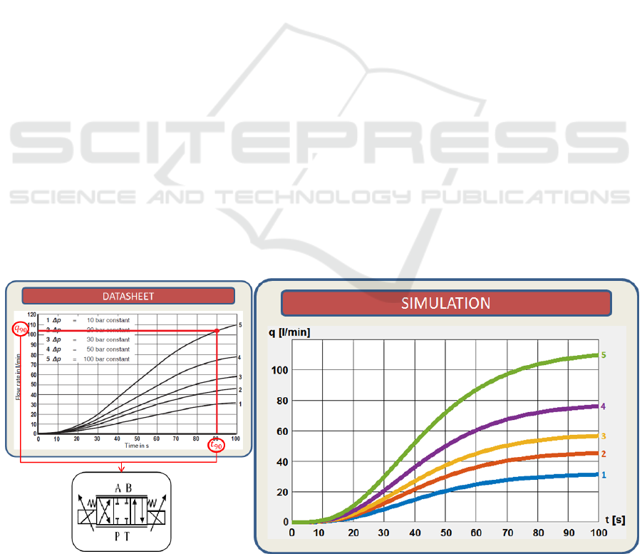
All components are configurable via parameters
typically found in data sheets, such as nominal flow
rates, piston areas or response times. Figure 1 shows
a flow rate diagram given by a proportional valve
data sheet. A single point taken from said diagram is
enough to configure our corresponding component,
which results in the simulation also show in the
figure.
Figure 1: Proportional valve model configuration and simulation results.
SIMULTECH 2017 - 7th International Conference on Simulation and Modeling Methodologies, Technologies and Applications
128
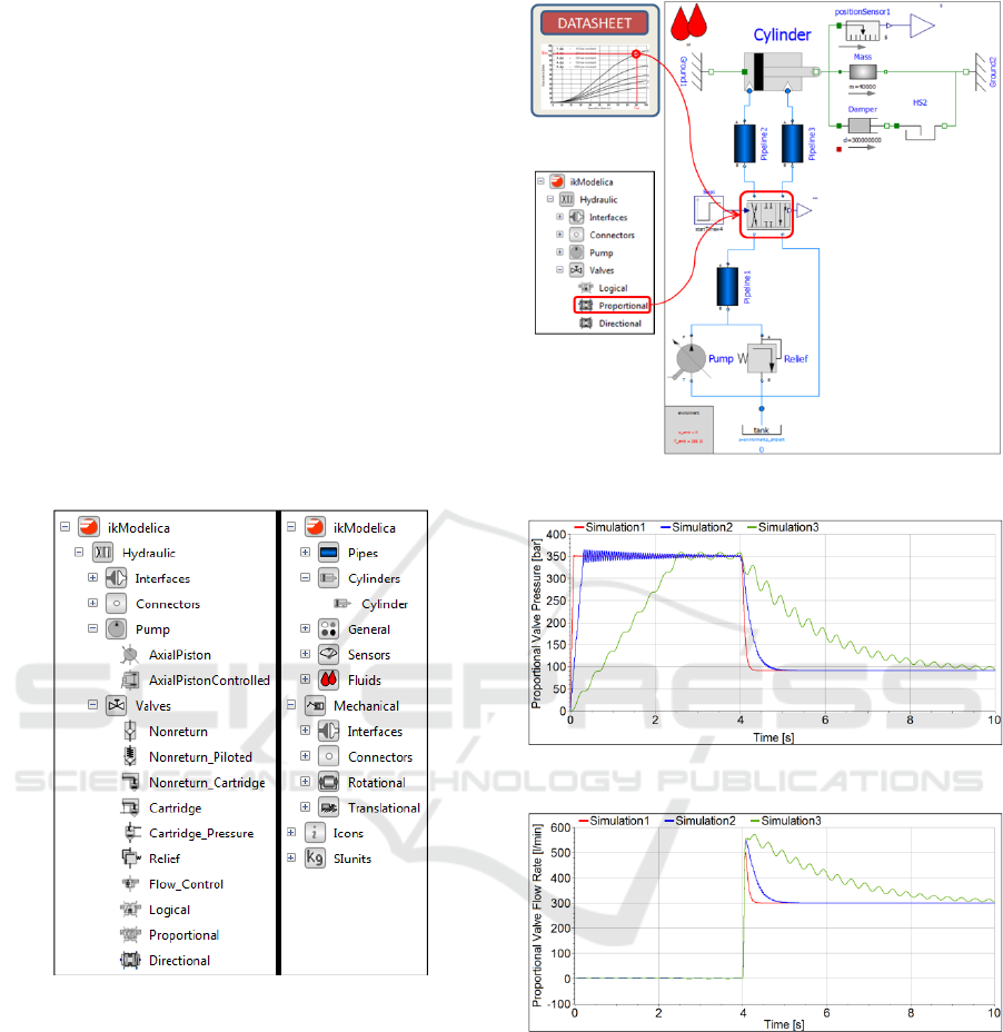
3.2 Model Assembly
A simple case study is presented here to illustrate
circuit model assembly from the components in our
OpenModelica library. Figure 3 shows a model with
a cylinder, a proportional valve, a constant
displacement pump, a relief valve and three
pipelines. The cylinder pushes on a considerable
mass and, when extended sufficiently, comes in
contact with a damper, which may be a simple
representation of a deep drawing process. Model
assembly is done by dragging and dropping
components from the library, and configuration is
done from data sheets (Madin, B.
a
, 2016).
Although this model is rather simple compared
to typical hydraulic presses, it will give a taste of the
fidelity which is achievable with our library, while
still maintaining real-time capabilities with complex
models, as will be shown in section 0.
Figure 2: Our OpenModelica library.
Figure 4 shows the pressure at the P port of the
proportional valve during three different 10 second
simulations, the difference between which is the
length of the pipeline coming from the pump.
Simulations 1, 2 and 3 correspond to pipeline
lengths of 1, 10 and 100 meters, respectively. Note
that the pressure is initially 0 and, since the
proportional valve is closed, it grows as the pump
compresses oil into the pipeline. The pressure
stabilises at 350 bar, where the relief valve opens to
limit it. As pipeline length grows, pressure takes
longer to build up and oscillations appear.
4 seconds into the simulations, the proportional
valve is fully opened to make the cylinder extend.
Figure 3: Simple model.
Figure 4: Proportional valve port P pressure.
Figure 5: Proportional valve port P flow rate in litres per
minute.
Then, oil flows from the pump to the cylinder, and
pressure at port P goes down to the pressure
differential needed to get the pump's nominal flow
rate through the valve. Again, pressure drops slower
and in a more oscillating way as pipeline length
grows. This is due to the pipeline acting as a
pressurised reservoir, which requires more oil to
flow through the valve to drop a given pressure, as
shown by Figure 5.
Real-time HiL for Hydraulic Press Control Validation
129
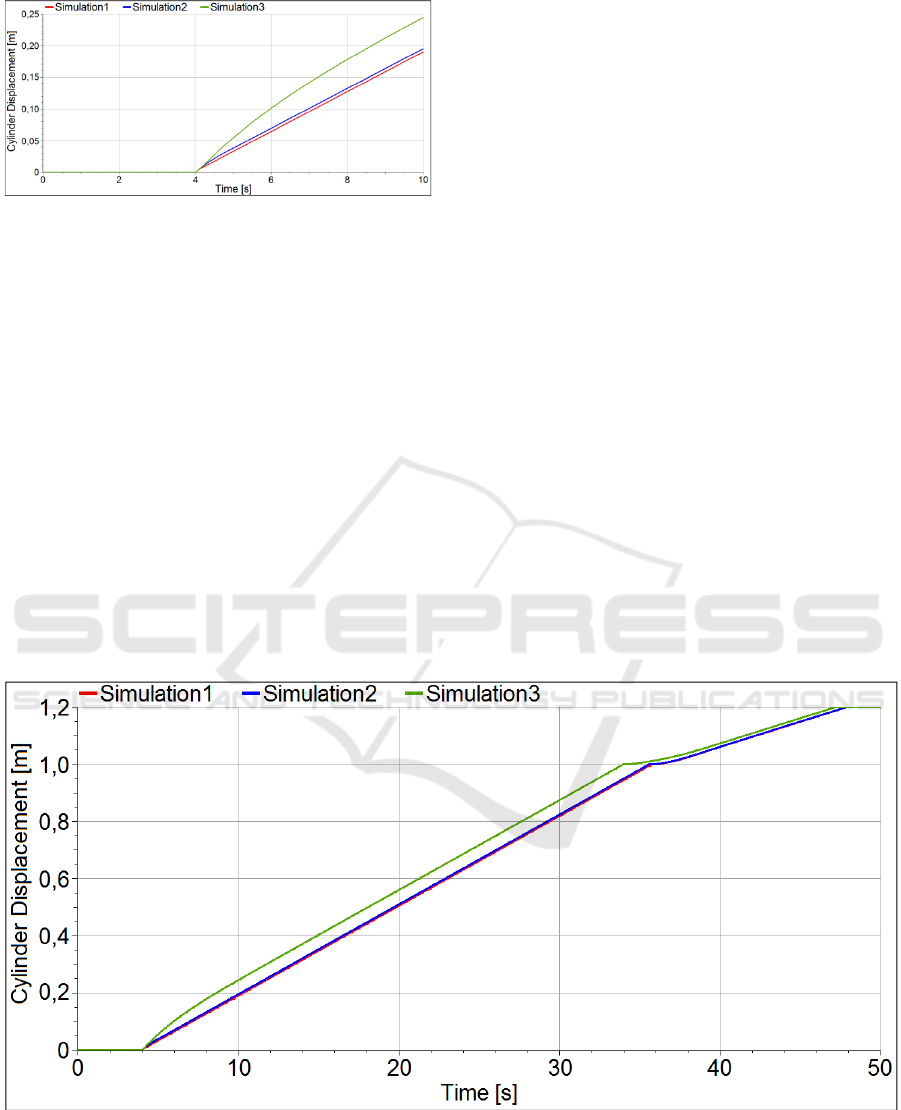
Figure 6: Cylinder displacement.
Figure 6 shows the cylinder displacement.
Initially, it is fully retracted and, 4 seconds into the
simulations, when the valve opens, it extends. The
pipeline going from the pump to port P on the valve
acts as an accumulator, and provides an initial boost,
which gets larger as the pipeline gets longer. The
cylinder subsequently settles to a constant speed,
dictated by the pump's nominal flow rate.
Figure 7 shows what happens afterwards. The
cylinder continues to extend until it makes contact
with the damper. This results in the cylinder
extension slowing down to a speed dictated by
maximum pump pressure and valve flow
characteristics. Note that pressure buildup in the
longer pipeline requires a longer time, which results
in the cylinder displacement in simulation 3 again
getting closer to that of simulations 1 and 2.
4 VALIDATION CASE STUDY
4.1 Press Model
For the case study presented here, a hydraulic press
circuit based on a commercial press has been
modelled, which uses a subset of the components in
the library described by section 0.
The model has been assembled exactly as the
circuit design drawings are, i.e. by placing all
components on a graphical interface and connecting
the ports. Component parameters have then been
directly taken from publicly available component
data sheets. Without further abstraction or
simplification efforts, the model is real-time capable
and provides as much fidelity as is possible to
validate with the available design data.
The press model features 9 cylinders, 9
proportional valves, 2 pumps, multiple non-return,
pressure relief and cartridge valves and multiple
pipelines.
A controller has been implemented in Simulink
®
,
based on the original press controller, which is
implemented on traditional motion control hardware.
This has allowed the parallel model and controller
development described in section 0.
Figure 7: Cylinder displacement until contact is made with damper.
SIMULTECH 2017 - 7th International Conference on Simulation and Modeling Methodologies, Technologies and Applications
130
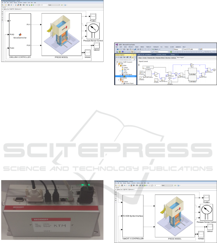
Figure 8: Software in the Loop validation.
The press model has been included in the Simulink
®
project via a functional mock-up unit (FMU) for co-
simulation (Chen, W.
a
et al., 2011). The Simulink
®
control algorithms have then been run in parallel
with the press model, and adjusted based on control
response until the latter has been considered
appropriate.
4.2 Hardware-in-the-Loop
The validated Simulink
®
control algorithms have
been embedded in the Beckhoff industrial PC shown
by Figure 9, via its real-time system TwinCAT 3.
This would be their definitive form for
commissioning. However, HiL validation is
possible, due to the press model's real-time
capability (Sun, P. et al., 2002; 2005; 2006 and
Ferreira, J.A.
a
et al., 1999).
Figure 9: Industrial PC used for HiL validation.
The press model has been separated from the control
algorithms, and communicated with the latter via
TwinCAT's ADS blocks. Running on the Windows
CPU of the industrial PC, it keeps up with the real-
time execution of the control algorithms on
TwinCAT, and generates the sensor signals based on
the press dynamics and the commands it receives
from the controller.
A Simulink
®
project has been created to build the
TcCOM object and export the controller from this
software into TwinCAT. This method connects
Simulink
®
blocks directly to the PLC syncrhonizing
both clocks in real-time. The controller was exported
as a S-Function with a similar behaviour of the
initial control (Figure 10).
Figure 10: TcCOM Object with the controller developed
in Simulink
®
and embedded in TwinCAT 3.
TwinCAT is capable of executing this module in
real-time assigning a task. This process is similar to
the one followed by the PLC to create and run the
Program Organization Units (POU’s) and the main
program. The TcCOM Object execution time was
configured in the task, and has to be similar to the
one selected in Simulink
®
during the design stage.
The HiL methodology was developed connecting
the TcCOM Object with the Simulink
®
simulation.
In this project, the controller was replaced with a
“TC ADS Symbol Interface” capable of
communicating Simulink
®
simulation with the
controllers running in TwinCAT (Figure 11).
Figure 11: Hardware in the Loop validation.
The results of both SiL and HiL validations are in
this case similar, as expected. Some variables are
shown by Figure 12 and Figure 13. Note that
pressure response times and oscillations are
determined by valve response times, pipe
dimensions, oil compressibility, head losses and, in
general, by all the circuit characteristics which are
specified by the hydraulic design documentation.
Real-time HiL for Hydraulic Press Control Validation
131
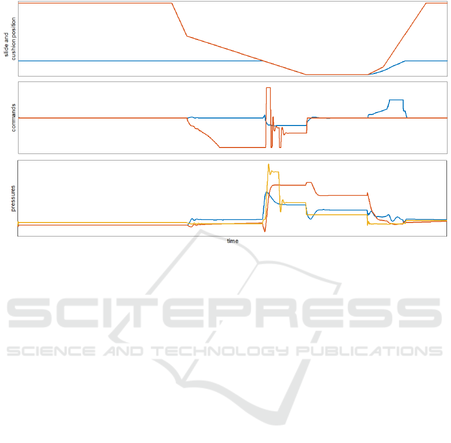
Figure 12: Validation results.
After this HiL validation, the controller is ready
for deployment on the press, pending the configu-
ration of the industrial PC for communication with
its instruments. However, a virtual commissioning is
possible, in which the press model is moved to a
system capable of physically replicating all the
sensor and actuator communications and signals.
This, due to its relative cost in terms of input and
output cards necessary for said system, has been
excluded from this case study, and is reserved for
actual press commissioning processes, where the
savings generated by the virtual commissioning
outweigh its cost.
5 CONCLUSIONS
A modelling methodology is sought for hydraulic
press virtual commissioning. Full integration with
engineering processes and real-time capabilities are
the primary requirements.
It has been argued here that said methodology
can profit from existing physical modelling
packages, among which is OpenModelica. Existing
component libraries are however not generally
focused on virtual commissioning and systems
engineering needs, and do not therefore typically
fully accomodate said requirements.
We develop and maintain an OpenModelica
library which specifically targets virtual
commissioning and allows high-fidelity modelling
of hydraulic presses, based on publicly available
data sheet parameters, at every stage of the
development cycle, including real-time HiL
validation.
Some of said libary's characteristics and
capabilities have been presented here, and a case
study has been described, in which a commercial
hydraulic press model has been run on a Beckhoff
industrial PC for controller HiL validation.
This methodology integrates well with the
controller development cycle. However, it requires
an additional effort to model presses in
OpenModelica. As it has been argued, said effort is
moderate, it accomodates the systems engineering
skillset and provides a sufficient reward in terms of
cost and risk reduction. However, it fragments the
systems engineering efforts, because circuit design is
duplicated, since OpenModelica is not sufficient to
produce all the necessary system documentation, e.g.
hydraulic drawings.
Further integration is therefore sought with the
system design tools, in order to draw circuit design
details from a centralised repository and produce
models automatically, thus reducing specific
modelling efforts during press development and
eliminating error-prone manual configuration. In
future works,we will reinforce this metholodgy by
means of automatizing the process with
OpenModelica Python Interface.
SIMULTECH 2017 - 7th International Conference on Simulation and Modeling Methodologies, Technologies and Applications
132

ACKNOWLEDGEMENTS
This work was supported in part by the Basque
Country Government (Research Project
ELKARTEK 2016, ALCON 4.0, KK-2016/00016
ALCON4.0).
This work was supported in part by the Guipuzkoa
Provincial Council (Research Project CONAMON
4.0, OF 215/2016 ES).
REFERENCES
Vilacoba, D.
a
, Perez, P.
a
, Gracia, A.
a
, Weber, P.
b
, 2016.
Conference Paper, Optimized press line orchestration
through virtual prototyping: A successful story in,
IEEE International Conference on Industrial
Technology, ICIT 2016, IEEE Xplore.
Qiu, X., Xiao, C., Tan, H., Hou, Y., Zhou, Y., 2016.
Article. Multi-software co-simulation for a large
robotic automatic stamping production line, in China
Mechanical Engineering.
Zadeh, L., Desoer, C., 1963, Linear System Theory: The
State Space Approach. McGraw Hill, New York.
Jung, D.
a
, Kang, D.
b
, Kang, M.
c
, Kim, B.
c
, 2014. Article.
Real-time pump scheduling for water transmission
systems: Case study, in KSCE Journal of Civil
Engineering, Springer.
Respondek, J.S., 2010. Article. Numerical simulation in
the partial differential equation controllability analysis
with physically meaningful constraints, in
Mathematics and Computers in Simulation Volume 81,
Issue 1 September 2010 Pages 120-132, Elsevier.
Crǎciun, O.
a
, Florescu, A.
a
, Munteanu, I.
b
, Bacha, S.
a
,
Radu, D.c, 2014. Article. Hardware-in-the-loop
simulation applied to protection devices testing, in
International Journal of Electrical Power and Energy
Systems, Science Direct.
Skoglund, T.
ab
, Dejmek, P.
a
, 2007. Article. A dynamic
object-oritented model for efficient simulation of fluid
dispersion in turbulent flow with varying fluid
properties, in Chemical Engineering Science Volume
62, Issue 8, April 2007, Pages 2168-2178.
ELSEVIER.
Winter, M.
a
, Taube, J.
a
, Froeschl, J.
b
, Herzog, H.-G.
a
,
2015. Conference Paper. From Simulation to
Testbench Using the FMI-Standard, in 12
th
IEEE
Vehicle Power and Propulsion Conference. IEEE.
Fritzson, P., 2011. Conference Paper. Modelica A cyber-
physical modeling language and the OpenModelica
environment, in 7
th
International Wireless
Communications and Mobile Computing Conference,
IEEE Xplore.
Linköping, 2014. Modelica
®
- A Unified Object-Oriented
Language for Systems Modelling, Modelica
Association, Version 3.3 Revision 1.
Gavrilakis, S., 1992. Article. Numerical simulation of low-
reynolds-number turbulent flow through a straight
square duct, in, Journal of Fluid Mechanics, Journal of
Fluid Mechanics.
Adiprasetya, M.H., Prihatmanto, A.S., 2015. Conference
Paper. Design and implementation of real time
simulator with Modelica, in 2012 International
Conference on system Engineering and Technology.
IEEE.
Madin, B.
a
, Ausiin, R.
b
, 2016. Conference Paper. Case
studies of the design and performance of one-way
surge tanks in pumped water and wastewater pipelines,
in 12
th
International Conference on Pressure Surges,
BHR Group Limited.
Chen, W.
a
, Huhn, M.
a
, Fritzson, P.
b
, 2011, Conference
Paper, Pages 19-24. A generic FMU interface for
modelica, in Proceedings of the 4
th
International
Workshop on Equation-Based Object-Oriented
Modelling Languages and Tools, EOOLT 2011.
Sun, P., Talaia, P.M., Rocha, A.M., Grácio, J.J., Ferreira,
J.A., 2002, Conference Paper. Experimental device
about automatic control of a hydraulic press, in
Proceedings of Asian Simulation Conference/the 5
th
International Conference, Proceedings of Asian
Simulation Conference.
Sun, P., Grácio, J., Ferreira, J.A., 2005. Conference Paper.
New experimental device of evaluating springback in
sheet metal forming, in Materials Science and
Technology 2005 Conference, Materials Science and
Technology.
Sun, P., Grácio, J.J., Ferreira, J.A., 2006. Article. Control
system of a mini hydraulic press for evaluating
springback in sheet metal forming, in Journal of
Materials Processing Technology, ELSEVIER.
Ferreira, J.A.
a
, De Oliveira, J.E.
b
, Costa, V.A.
a
, 1999.
Article. Modeling of hydraulic systems for hardware-
in-the-loop simulation: a methodology proposal, in
Fluid Power Systems and Technology – 1999 (The
ASME International Mechanical Engineering
Congress and Exposition). ASME.
Ferreira, J.A., De Almeida, F.G., Quintas, M.R., 2002,
Article, Pages 237-248. Semi-emprirical model for a
hydraulic servo-solenoid valve, in Proceedings of the
Institution of Mechanical Engineers. Part I: Journal of
Systems and Control Engineering, SAGE journals.
Real-time HiL for Hydraulic Press Control Validation
133
