
Scenario Interpretation based on Primary Situations for Automatic
Turning at Urban Intersections
David Perdomo Lopez
1
, Rene Waldmann
1
, Christian Joerdens
1
and Ra
´
ul Rojas
2
1
Automated Driving, Volkswagen Group Research, Wolfsburg, Germany
2
Department of Mathematics and Computer Science, Freie Universi
¨
at Berlin, Berlin, Germany
Keywords:
Automated Driving, Scenario Interpretation.
Abstract:
Even for a human driver, urban intersections represent probably the most difficult scenarios, in which the
driver could be overloaded by understanding the traffic rules, predicting the intention of other objects, etc. The
complexity of these scenarios makes the task of automated driving at intersections a very difficult challenge.
Thus, we propose an approach that aims to reduce the complexity of the scenario interpretation by breaking
down the problem into a set of primary situations linked over time. Based on the combination of four primary
situations, the scenario interpretation should enable the corresponding planning that guides the ego vehicle
along a driving corridor.
1 INTRODUCTION
Driver assistance and automated driving systems have
become a very emerging field of research in the last
decades. In (Okuda et al., 2014) the authors review
the most promising approaches and techniques used
in these kind of systems.
Considering the basic conceptual flowchart in Fig.
1, the automated driving process can be simplified
into four main steps: (1) perception, (2) scenario in-
terpretation, (3) planning and (4) control. In this
basic representation, the perception module provides
the description of the surrounding world to the next
module. Then, the scenario interpretation module
achieves the comprehension of the relevant informa-
tion for the following planning and control stages.
Figure 1: Basic conceptual flowchart for automated driving
based on four main steps. The environment perception (1)
represents the low level processing of sensors and a priori
data (e.g. image processing, object recognition and track-
ing, localization and mapping, etc.). The scenario interpre-
tation (2) corresponds with the understanding of the pro-
cessed data. The planning (3) makes the proper decisions
and delivers them to the control module (4), which finally
provides the adequate signals in terms of steering and ac-
celeration.
Obviously, the more inaccurate the perception is,
the more complex is the interpretation of the provided
data. But even if the perception provides accurate in-
formation about the surrounding of the ego vehicle,
the problem is not simple. The large number of possi-
ble collisions with other road users at urban intersec-
tions makes the problem a very complex challenge.
For this reason, the proposed concept aims to enable
the decision making for automated turning at urban
intersection in a simple manner.
In this paper, we first describe the general con-
cept of scenario interpretation for automated driving.
Then, section 3 gives an overview of related work at
intersections. After that, we address the problem in
section 4. Hereafter, the proposed approach is ex-
plained in section 5. And finally, section 6 concludes
the paper.
1.1 Definition of Scenario
Interpretation
Before going into further details, two concepts have
to be defined: scenario and interpretation. The au-
thors in (Geyer et al., 2014) propose a definition for
some relevant terms in the automated driving context
(situation, scene, scenario, etc.). As can be seen in
Fig. 2, the scenery is defined as the combination of
all possible single static elements (e.g. road network,
number of lanes, crosswalks, position of traffic lights,
speed limits, etc.). The scene contains the scenery and
the information of all dynamic objects with their cor-
Lopez, D., Waldmann, R., Joerdens, C. and Rojas, R.
Scenario Interpretation based on Primary Situations for Automatic Turning at Urban Intersections.
DOI: 10.5220/0006150300150023
In Proceedings of the 3rd International Conference on Vehicle Technology and Intelligent Transport Systems (VEHITS 2017), pages 15-23
ISBN: 978-989-758-242-4
Copyright © 2017 by SCITEPRESS – Science and Technology Publications, Lda. All rights reserved
15
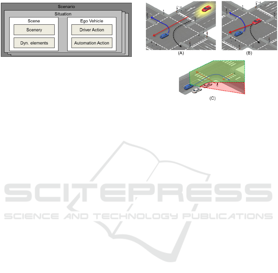
Figure 2: Definition of the term scenario by (Geyer et al.,
2014).
responding states. The situation consist of the scene
and optional ego vehicle. In this context, the situa-
tion describes the current state, which could persist
several seconds until some conditions or criteria are
filled. On the contrary, the scenario describes differ-
ent states over the time, so that it contains at least one
situation, in which the last situation corresponds to
the last relevant situation.
Another definition is used in (Domsch and Negele,
2008). Domsch et al. propose a definition for terms
like: driver-situation, traffic situation, scenario, etc..
A driving situation is described with the parameters:
static (road network, traffic rules, priority, etc.), dy-
namic (objects, traffic lights phases, etc.) and diverse
(weather, road conditions, etc.). Moreover, Ulbrich et
al. (Ulbrich et al., 2015) present a coherent review
and comparison of these terms and propose their own
definitions.
On the other hand, the term interpretation refers
to the act of explaining the meaning of something. In
this sense, the perception module makes a description
of the surrounding of the vehicle and the scenario in-
terpretation module gives a proper meaning to this in-
formation. Accordingly, the scenario interpretation at
intersection involves the following tasks:
• Filtering relevant information
• Using the information of the road network with
corresponding logical correspondences
• Predicting the intention of other vehicles
• Handling occlusions
• Achieving risk assessment
• Considering logical traffic rules
• Handling the right of way
• Handling localization uncertainty
• Etc.
For example, in the first example of Fig. 3 (A) the
ego vehicle (in blue) is turning to the left and another
vehicle (in red) is approaching the intersection. It be-
comes obvious that it is crucial to know on which lane
the other car is driving to determine a possible colli-
sion with the ego vehicle: if the red car is driving on
Figure 3: Examples of scenario interpretation at intersec-
tions. (A) Intention prediction of an oncoming vehicle
with inaccurate position: the ego vehicle (in blue) is mak-
ing a left turn maneuver (blue path) and other vehicle (in
red) is approaching the intersection. The yellow blob sur-
rounding the other vehicle represents the uncertainty of its
measured position. In case that the other vehicle is driving
forward (red path), there is an intersection of both paths.
Otherwise (black dotted path), there is no collision between
both vehicles. (B) Intention prediction of an oncoming
vehicle with accurate position: the ego vehicle is turn-
ing left and the other vehicle (which is already in the in-
tersection and its position is accurate enough) could drive
forward or turn left. (C) Handling occlusion while ap-
proaching an intersection: the ego vehicle is approaching
the intersection and aims to turn to the right. Due to an ob-
stacle (e.g. another vehicle), the occlusion impede to detect
a crossing pedestrian at the right side of a zebra crossing.
The green and red colored regions indicate the perceptible
and non perceptible areas respectively.
its most left lane, it is just allowed to turn to the left,
so that a collision with the ego vehicle is not expected.
Alternatively, if the other car is not driving on its most
left lane, its path has a conflict with the ego’s driving
corridor. Thus, if the position of other vehicles (or
ego vehicle) is not accurate enough (e.g. due to loca-
tion uncertainty), the scenario interpretation module
has to manage the uncertainty of the information in
order to understand how critical is the situation.
But even considering a perfect accuracy of the po-
sition of both vehicles, a proper intention prediction
could be crucial (depending on the road network and
its turning possibilities). As shown in 3 (B), the ego
vehicle is turning left and the other car could perform
two maneuvers: driving forward or turning left. In
this case, the accuracy of the state of the other car
(e.g. yaw, velocity, etc.) is crucial to achieve a proper
intention prediction.
Moreover, an important task of the scenario inter-
pretation module is to handle occlusions. In this way,
it is not only important to understand the provided in-
VEHITS 2017 - 3rd International Conference on Vehicle Technology and Intelligent Transport Systems
16

formation, but also to take into account which infor-
mation is missing. For example, in Fig. 3 (C) the
ego vehicle (blue) is approaching the intersection and
an obstacle (a parked car in white) impede to detect
a pedestrian. For this given scenario, the first pedes-
trian (behind the obstacle) is not detected due to the
occlusion, but a proper scenario interpretation should
be able to interpret the occlusion as a critical miss-
ing information. Consequently, it is unclear if more
pedestrians approach the crosswalk or not.
1.2 Scenario Interpretation at Urban
Intersections
Due to the complexity of scenarios at urban intersec-
tions, it becomes obvious that a proper scenario in-
terpretation is required. In recent years several meth-
ods have been proposed to tackle this problem. Vacek
et al. (Vacek et al., 2007) present an approach for
a case- and rule-based situation interpretation using
description logic. The raw data from the sensors is
stored and transformed into a higher level represen-
tation. The different expected behavior of other ve-
hicles generates the linkage of other cases over time
with corresponding probabilities for every different
situation. Since the number of different options be-
comes very large at intersections, the computational
cost for the description logic reasoning constitutes the
main drawback of this approach. Logic description is
also used by Huelsen et al. (H
¨
ulsen et al., 2011) to de-
scribe an ontology that represents the road networks,
objects, their relations and the corresponding traffic
rules. The goal is to reason relations, objects, traf-
fic rules (e.g. hasRightOfWay or hasToYield) using
inference services. Even keeping only necessary in-
formation for reasoning, the main drawback of this
approach are the high computational costs. There-
fore, this approach is insufficient for real-time com-
putation.
Geyer et al. (Geyer et al., 2011) present a method
based on the cooperation between the driver and the
system with the Conduct-By-Wire (CBW) concept.
Depending on the current driving situation, and the
required information, the so-called gates are identi-
fied. A driving situation is described with three types
of parameters: Static (road network, traffic rules, pri-
ority, etc), dynamic (objects, traffic lights phases, etc.)
and diverse (weather, road conditions, etc.). The sys-
tem analyzes the required information at the gates.
Consequently, different automation levels are set to
make easier the cooperation between the system and
the driver. To determine which information is needed,
a occupancy map and entry directions at the intersec-
tion are set. The CBW approach was also used by
Schreiber and Negele (Schreiber et al., 2010) to de-
velop of a maneuver catalog from the driver point
of view. The focus is to analyze what the driver is
expected to do. This information is combined with
a set of maneuvers that should cover every possible
traffic and driving maneuver. The authors in (Alonso
et al., 2011)present two methods for priority conflict
resolution (priority charts and priority levels) using a
vehicle-to-vehicle (V2V) communication system as a
requirement. The first method uses vectors to describe
the turning possibilities of all vehicles and their corre-
sponding priority signs. Then, an auxiliary table con-
taining all possible vectors associated with Boolean
values is used to indicate if the ego vehicle has to
move or stop. This table contains 111 different cases
without considering the traffic signs combinations (3
for one vehicle, 27 for two vehicles, and 81 for three
vehicles). On the other hand, the second proposed
method aims to determine whether the ego vehicle can
continue or must wait by interpreting the different pri-
ority levels (using an auxiliary truth table to detect po-
tential conflicts with other vehicles). The authors pro-
pose a flowchart to handle the right of way problem.
These two proposed methods depend on an specific
topology (in this case a two road intersection). More-
over, V2V communication is required. Although the
focus of (Lotz and Winner, 2014) is not to turn auto-
matically at urban intersections, the authors propose
a maneuver-based planning for automated vehicles.
Based on the desired maneuver (or set of maneuvers
over the time) the proposed system plans the proper
lane change by approaching the intersection. The ap-
proach was tested in a multi-lane road network with-
out other road users.
2 PROBLEM DESCRIPTION
The described problem is focused on understanding
the perceived information of the environment at urban
intersections. In this sense, the interpretation should
enable to plan the proper vehicle motion for turn-
ing at urban intersections with different precedence
states. Unfortunately, there is no international regula-
tion that controls the traffic flow at intersections in a
unique manner for all the possible scenarios all over
the world. Therefore, this work considers the regu-
lation described in the Vienna Convention on Road
Signs and Signals (for Europe, 2006) and the German
regulation (f
¨
ur Straßen und Verkehrswesen (FGSV),
2010) in particular. A coherent way to address the
problem is to describe an intersection in a simple
manner. Therefore, we try to make a conceptual de-
scription of the scenario answering three questions
Scenario Interpretation based on Primary Situations for Automatic Turning at Urban Intersections
17
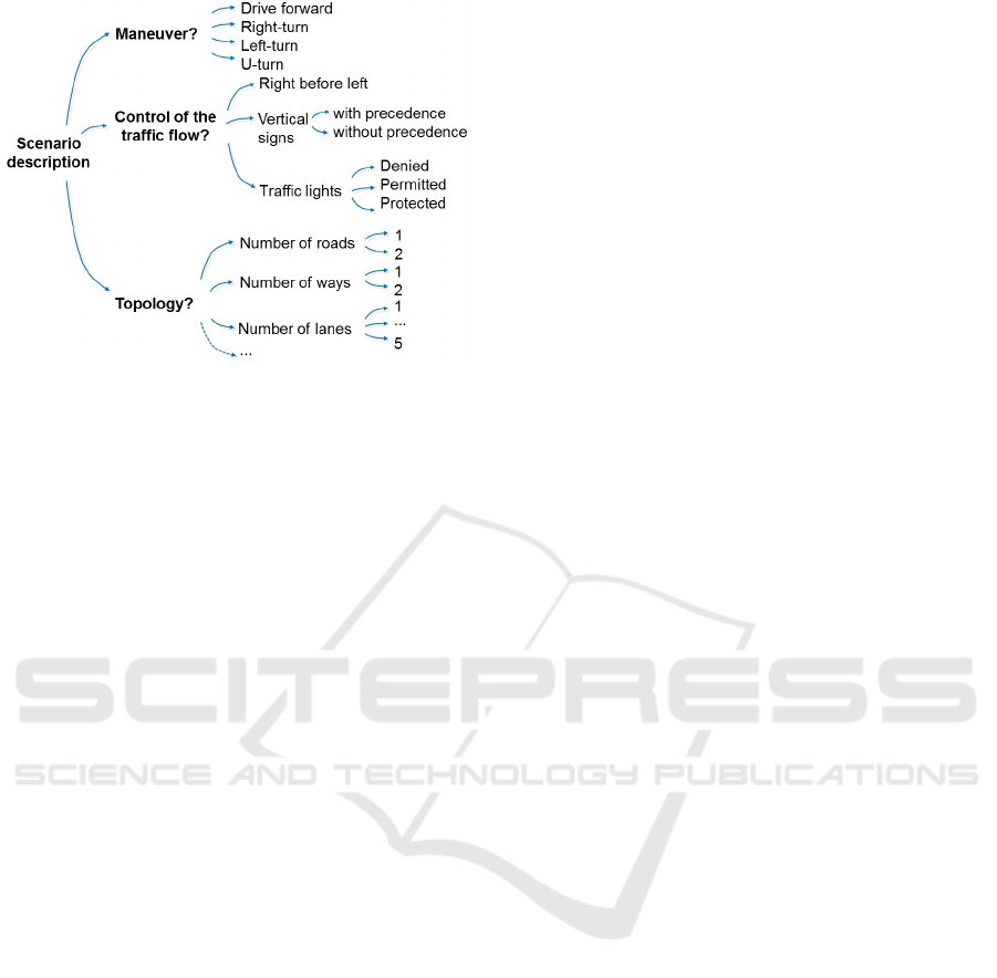
Figure 4: Simple classification to describe an intersection.
(cf. 4):
• Which maneuver is making the ego vehicle?
• In which way is the traffic flow controlled?
• What is the topology of the intersection?
Therefore, the traffic flow at intersections can be
controlled in three different ways: by the right of way
rule, with vertical signs or traffic lights. The ego ve-
hicle intention and the control of the traffic flow, yield
different scenarios and potential conflicts with other
vehicles or vulnerable road users (VRU). Fig. 5 il-
lustrates the different possible scenarios considering
a simple intersection topology. This classification is
an improved version of the method proposed by Fas-
tenmeier (Fastenmeier et al., 1995):
In this sense, every possible state of the intersec-
tion defines the control of the traffic flow (from an ego
perspective, i.e. it indicates how ego vehicle should
handle the right of way). The following intersection
states are considered:
Denied: a common circular red traffic light has been
detected. The ego vehicle has to stop as long as
the traffic light color is red.
Permitted: a common circular green light has been
detected, so that the ego vehicle is allowed to turn.
However, the ego vehicle has to give way to on-
coming vehicles while turning left and VRU have
priority in parallel conflicts.
Protected: a green arrow traffic light has been de-
tected. According to (f
¨
ur Straßen und Verkehr-
swesen (FGSV), 2010), the path of the ego vehicle
to complete the turning maneuver has no conflicts
with other road users.
Permitted on Red: a static sign with a green arrow
has been detected beside a red traffic light. Even
if the traffic light indicates red, the ego vehicle is
allowed to turn if there is no potential collision
with other crossing/oncoming vehicles.
Right before Left: a vertical sign indicates that the
rule right before left has to be applied or no verti-
cal sign controls the traffic flow, and consequently,
this rule is applied by default.
With Precedence: a priority road sign has been de-
tected, so that other crossing vehicles are required
to give way to the ego vehicle.
Give Way: a give way is used to notify the ego vehi-
cle that it has to give way to other crossing vehi-
cles.
Stop: the detected stop sign implies that the ego ve-
hicle is required to stop (even if any other vehicle
is crossing) and give way to other vehicles.
The other possibility to describe an intersection is
to consider its topology. Other authors (Gersten-
berger, 2015) have analyzed in detail the most com-
mon topologies to determine the relation between the
different topologies and the traffic accidents. Consid-
ering the large number or possible different topolo-
gies, we take for granted that a scenario interpreta-
tion based on specific topologies is not appropriate.
Therefore, the proposed solution aims to achieve a
left and right turn maneuver independently on the in-
tersection topology.
3 PROPOSED APPROACH
The proposed approach aims to make the interpreta-
tion of the scenario (and further planning) easier by
breaking it down into primary situations. Therefore,
we first describe in detail how we define a scenario
based on primary situations and finally we explain
how the ego vehicle is guided to complete the turn-
ing maneuver.
3.1 Scenario Interpretation based on
Primary Situations
A scenario contains mainly three important concepts:
the linkage of the expected primary situations, the ego
intention and the information of the intersection state,
which defines how the traffic flow is controlled from
an ego perspective. In this way, the primary situa-
tions are defined by potential conflicts with other road
users and further relevant. A single primary situation
VEHITS 2017 - 3rd International Conference on Vehicle Technology and Intelligent Transport Systems
18
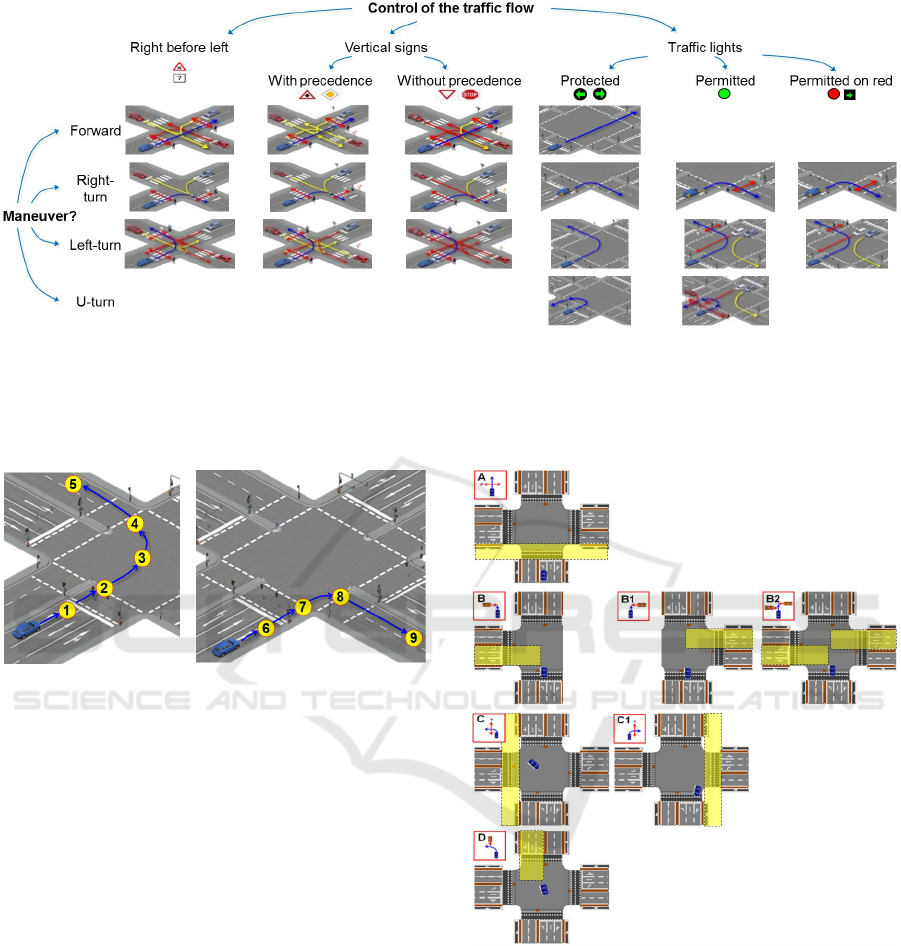
Figure 5: Classification of possible scenarios at a simple intersection topology considering the desired maneuver and right of
way. Every column represents a different maneuver of ego vehicle with its path (blue). Every row corresponds to a different
manner to control the of right of way. All possible path of other vehicles with a potential collision with ego vehicle is colored
depending on its priority. The other vehicles (or VRU) with a red path have priority with respect to ego vehicle. The other
vehicles with yellow paths are required to give way to ego. The dotted arrows indicate paths of other vehicles without an
intersection with ego’s path.
Figure 6: Nine primary target points for automatic turning
left or right at intersections.
requires at least a target point, its corresponding re-
gion(s) of interest (ROI) and the relevant objects in-
side this ROI(s). This concepts are explained down
bellow. Every target point indicates the position and
velocity of the ego vehicle along a determine driving
path (or trajectory). It represents the stages where a
single primary situation is expected, so that the set
of target points defines the maneuver of the vehicle.
As shown in Fig. 6, the set of primary target points
for turning at intersections can be automatically cal-
culated based on the road network information..
Furthermore, every ROI describes a geometric
area (as 2D polygon) that has to be observed for every
primary situation. It represents the area where rel-
evant objects are expected. For example, if a zebra
crossing was detected in front of the ego vehicle, the
ROI for this situation should represent the area where
pedestrians could be. In other words, the ROIs indi-
cate the areas where objects (other vehicles or VRU)
could appear and produce potential conflicts with the
ego vehicle. Therefore, the ROIs can be calculated
automatically considering the road network informa-
tion (i.e. considering the paths intersection of the ego
Figure 7: Primary situations (A, B, B1, B2, C, C1, D) with
corresponding region of interest (yellow semi-transparent
rectangles) for a generic intersection and ego position (col-
ored in blue).
vehicle and other road users).
As it is illustrated in Fig. 7, we propose four pri-
mary situations with their corresponding ROIs (A, B,
C, D):
A: a perpendicular conflict with VRU (e.g. a cross-
walk, zebra crossing or bike lane) is in front of the
ego vehicle. The corresponding ROI consists of
the conflict and its surround area where potential
objects are expected. For example, if the ego ve-
Scenario Interpretation based on Primary Situations for Automatic Turning at Urban Intersections
19
hicle is approaching the intersection and there is
a perpendicular bike lane in front of it, the ROI
is automatically calculated considering the area
that the ego vehicle aims to overdrive and the sur-
rounding area along the bike lane where a possi-
ble bicycle could be. Obviously, the size of the
area along the bike lane is determined by the ego
velocity (the faster ego vehicle drives, the larger
should be the size of the area along the bike lane).
B: the ego vehicle has a conflict with a left-cross
lane (e.g. at a T-form intersection without right-
crossing lanes). Here, the ROI is calculated con-
sidering the information of the road network along
the possible left-cross lanes. B1 is not considered
a primary situation its own, but a mirrored version
of B, in which the cross lane comes from the right
side. In addition, B2 corresponds to a combina-
tion of B and B1 (e.g. at a X-form intersection).
C: the ego vehicle has a conflict with a parallel cross-
walk, zebra crossing or bike lane. Perpendicu-
lar and parallel conflicts with VRUs by turning
at intersections have to be handled in a different
manner compared to situation A. For example, at
an intersection controlled with traffic lights, when
the state is permitted, the ego vehicle has prece-
dence with respect to the VRUs crossing a per-
pendicular crosswalk. On the contrary, the ego
vehicle has no precedence with respect to VRUs
crossing a parallel crosswalk (this is graphically
explained in Fig. 5).
D: the ego vehicle has a conflict with an oncoming
vehicle.
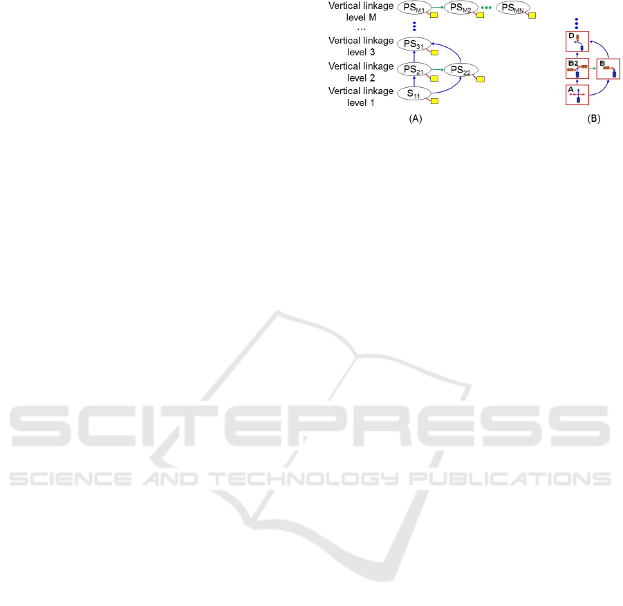
The linkage of the primary situations represents
the order in which consecutive single primary situ-
ations are expected and the relations between them.
Accordingly, the situations can be vertically or hori-
zontally linked: a vertical link indicates that the next
primary situation is expected at a certain distance
(and, depending on the variation of the ego velocity
over time). But a horizontal link denotes that another
different primary situation could also be expected at
the same distance. The level of the vertical and hor-
izontal linkage is denoted by i and j respectively. In
this sense, a scenario (S) denotes the connections of
primary situations (PS
i j
):
S = {PS
11
, ..., PS
1N
1
;
PS
21
, ..., PS
2N
2
;
...;
PS
M1
, PS
MN
M
},
(1)
where M is the number of different vertical linkage
levels and Ni is the number horizontal linkage levels
Figure 8: Concept of a scenario based on linkages of pri-
mary situations. (A) and (B) illustrates the concept and a
given example respectively. Every ellipse (PS
i j
) represents
a primary situation with its corresponding relevant infor-
mation. The blue and green arrows indicate the vertical (i)
and horizontal ( j) linkage level respectively. The yellow
rectangles represent the information of the ROIs and the de-
tected objects. In this example, the first situation PS
11
is
linked vertically with the primary situations PS
21
and PS
22
,
which are horizontally linked between them (green arrow)
and once again vertically linked with PS
31
.
for every corresponding vertical level (i). The concept
is illustrated in Fig. 8.
For example, the ego vehicle is approaching the
intersection with the intention of turning to the left
without precedence. Firstly (i.e. vertical linkage level
1), a perpendicular crosswalk is detected, so that the
first situation PS
11
corresponds to the primary situa-
tion A. In this case, the yellow rectangle represents
the ROI around the crosswalk and the detected ob-
jects. Lets say that the information of the road net-
work is not accurate (or trustworthy) enough, and
consequently the interpretation module can not guar-
anty that the intersection has a T- or X-form. In this
case two possibilities are expected: PS
11
= B (left-
cross lane) and PS
22
= B2 (left and right-cross lane).
Furthermore, independently on which primary situa-
tion is the most probable at the vertical linkage 2, the
next expected situation (PS
31
) is D (i.e. we expect on-
coming vehicles inside the corresponding ROI). And
so on, the scenario is interpreted by generating the
linkage of primary situations over time and continu-
ously updating these linkages. For this given exam-
ple, as ego vehicle is getting closer to the intersection,
the road network information becomes more accurate,
so that the vertical linkages become also more robust.
In other words, the linkages are updated taking into
account the information of the perception module and
optimizing the connections between the primary situ-
ations.
3.2 Planning the Maneuver
Once the scenario is generated, the target points have
to be set according to the available information (e.g.
relevant objects or intersection state), so that the ego
VEHITS 2017 - 3rd International Conference on Vehicle Technology and Intelligent Transport Systems
20
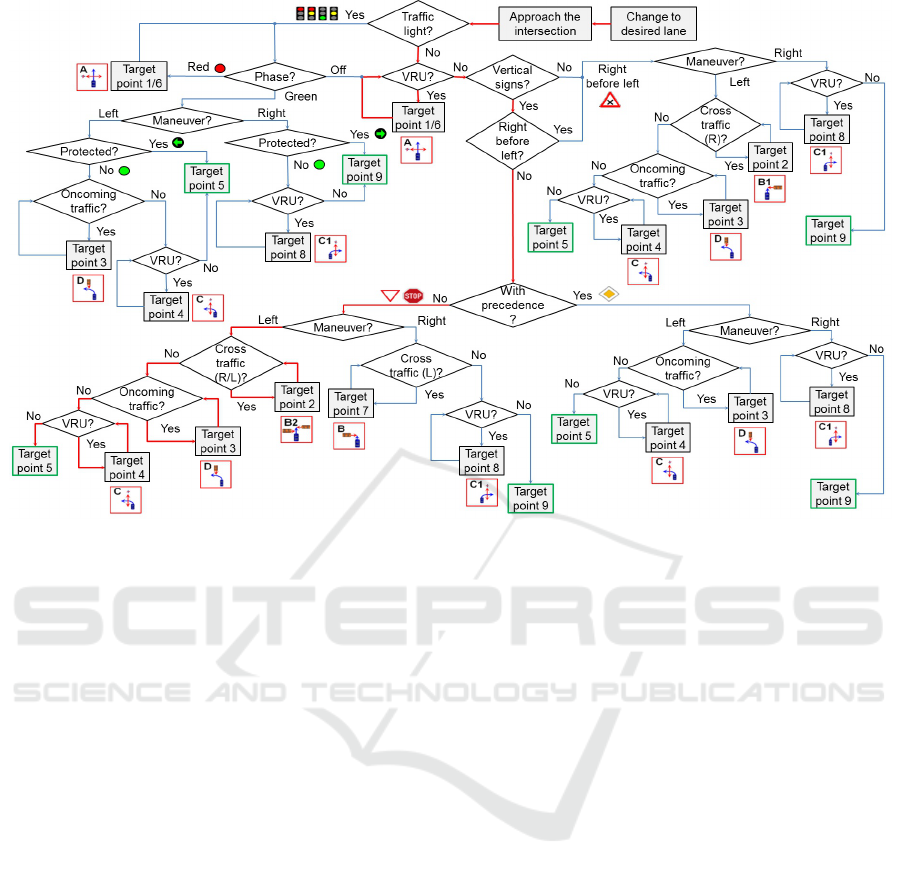
Figure 9: Flowchart for automated turning based on primary situations. It explains step by step the connection of the expected
primary situations and their according target points. The last target point guides the ego vehicle to the end of the turning
maneuver (rectangles with green border). A given example is highlighted in red (left turn without precedence).
vehicle is guided to achieve the whole turning maneu-
ver. Since the trajectory of the ego vehicle is part of
the scenario, the target points are set along a driving
path. The flowchart highlighted in Fig. 9 explains
which information is needed to set the proper target
points for every primary situation. For the sake of
clarity, the diagram has been kept simple by consid-
ering only a very basic topology. In other words, the
consideration of more complex topologies (e.g. han-
dling T- or X-form intersections) is omitted to ease its
representation and understanding. Furthermore, the
difference between an intersection state stop or give
way, and the intersection state permitted on red are
also omitted.
Once the ego vehicle approaches the intersection
and has done the proper lane change(s), the first re-
quired information is how plausible the existence of
traffic lights and vertical signs are. This determines
the first main branching of the flowchart, which is
based on how the traffic flow is controlled, namely by
traffic lights, vertical signs or the right before left rule.
In the given example (highlighted with red arrows in
the flowchart 9 any traffic light is detected. Then, a
primary situation A is expected depending on the ex-
istence of a perpendicular conflict with VRUs. Then,
the flowchart is divided into two branches depending
how the traffic flow is controlled, i.e., by vertical signs
or the right before left rule. In the given example a
yield sign was detected, and the ego vehicle intends
to turn left, so that both left and right possible cross-
ing vehicles have the right of way (primary situation
B2). Consequently, if the a collision with ego vehi-
cle and some crossing vehicle from both sides inside
the corresponding ROIs is predicted, the target point 2
forces ego vehicle to stop in front of the conflict area
so long as no collision is expected. Then, the next
primary situation D implies setting the target point 3,
in such a way as to avoid a collision with oncoming
vehicles. But in case that any collision is predicted
(e.g. because the are no oncoming vehicles in the cor-
responding ROI), the next target point 4 (primary sit-
uation C ) is set as long as the conflict area is not pass-
able. Otherwise, the left turn maneuver is completed
with the target point 5. An important advantage of this
concept is that a target point does not only indicate a
position, but also a desired velocity. This allows han-
dling occlusions in a simple manner. For example, in
case that the ego vehicle is making a right turn (see
Fig. 10) and an obstacle (e.g. other car) impedes to
observe the ROI completely, the scenario interpreta-
tion should not take for granted that the whole ROI is
free. In fact, a pedestrian could be in those parts of the
ROI that are not perceptible (in this example behind
the white car). As human drivers, we would probably
reduce the velocity because we are not sure if some
pedestrians are crossing.
Scenario Interpretation based on Primary Situations for Automatic Turning at Urban Intersections
21
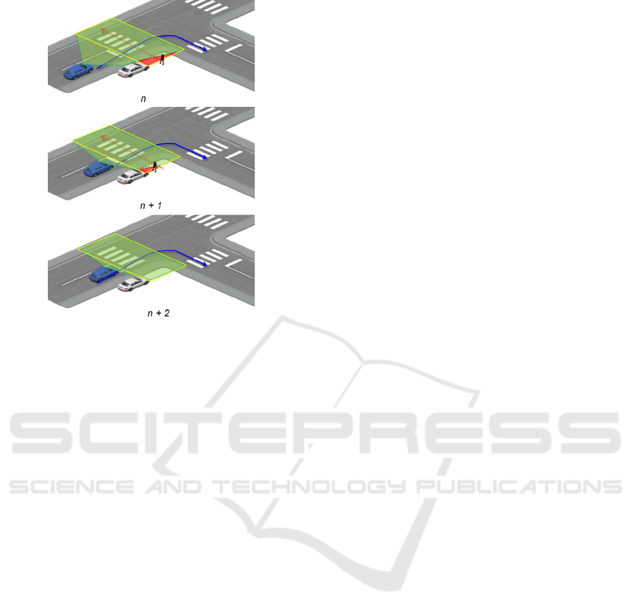
Figure 10: Occlusion example illustrated over the time (n,
n + 1 and n + 2). The ego vehicle (blue) is making a right
turn maneuver (blue path) and other vehicle (white) im-
pedes to observe the ROI (yellow rectangle) completely.
The perceptible and not perceptible areas are colored in
green and red respectively. The illustrated pedestrian and
its path (dotted red arrow) corresponds to a placed virtual
object.
The idea is to imitate cognitive human reaction in
a very simple way: setting a virtual object. This ob-
ject is placed representing the worst case (i.e. a pedes-
trian is crossing so that a collision with the ego vehicle
will occur). In the given example, a virtual pedestrian
is placed at the time n and n + 1. This placed object
causes that the prediction module set the target point
6 with a very low velocity (e.g. 5 Km/h), because a
pedestrian could be behind the white car.
4 CONCLUSIONS
In this paper a scenario interpretation approach for au-
tomated driving at intersections has been introduced.
The main goal of the proposed method is to make
the interpretation of the scenario and the further deci-
sion making easier. This has been achieved by break-
ing down the problem into four primary situations (or
combinations of them). After explaining the mean-
ing of the term scenario interpretation, an overview
of the related work was given. Then, we described
the problem taking into account the intention on the
ego vehicle and the intersection state that controls the
traffic flow. This analysis identified the potential con-
flicts with other road users in a simple manner. In
this way, the scenario consists of linkages of expected
primary situation over time, in which just the rele-
vant information is needed. These primary situations
are defined by the potential conflicts with other road
users and further information (target point, ROI, rele-
vant objects). Moreover, a flowchart to complete the
left and right turn maneuver was presented. This dia-
gram represents the combination of primary situations
over time facilitating to turn left/right automatically.
Compared to state-of-the-art solutions, a very impor-
tant advantage of our system is that it may be applied
independently of the intersections topology. Further-
more, it offers the possibility of handling occlusions
in a simple way.
Future research will focus on optimizing the pro-
cess of predicting the intersection state that controls
the right of way at the intersection. Moreover, re-
search work to analyze the computational cost of the
proposed approach have to be done. In this sense,
a detailed evaluation of the proposed approach and
its functionality over the time for real scenarios will
be achieved and compared with other techniques.
These future validation involves scenarios with dif-
ferent VRUs, weather conditions and topologies.
REFERENCES
Alonso, J., Milan
´
es, V., P
´
erez, J., Onieva, E., Gonz
´
alez, C.,
and De Pedro, T. (2011). Autonomous vehicle control
systems for safe crossroads. Transportation research
part C: emerging technologies, 19(6):1095–1110.
Domsch, C. and Negele, H. (2008). Einsatz von referenz-
fahrsituationen bei der entwicklung von fahrerassis-
tenzsystemen; 3. Tagung Aktive Sicherheit durch
Fahrerassistenz, April, pages 07–08.
Fastenmeier, W. et al. (1995). Autofahrer und Verkehrssi-
tuation. Neue Wege zur Bewertung von Sicherheit
und Zuverl
¨
assigkeit moderner Strassenverkehrssys-
teme. Number 33.
for Europe, U. N. E. C. (2006). Convention on Road Signs
and Signals of 1968. Geneva, Switzerland.
f
¨
ur Straßen und Verkehrswesen (FGSV), F. (2010).
Richtlinien f
¨
ur Lichtsignalanlagen (RiLSA).
Gerstenberger, M. (2015). Unfallgeschehen an Knoten-
punkten: Grundlagenuntersuchung zu Ursachen und
Ansatzen zur Verbesserung durch Assistenz. PhD
thesis, M
¨
unchen, Technische Universit
¨
at M
¨
unchen,
Diss., 2015.
Geyer, S., Baltzer, M., Franz, B., Hakuli, S., Kauer, M.,
Kienle, M., Meier, S., Weißgerber, T., Bengler, K.,
Bruder, R., et al. (2014). Concept and development of
a unified ontology for generating test and use-case cat-
alogues for assisted and automated vehicle guidance.
Intelligent Transport Systems, IET, 8(3):183–189.
Geyer, S., Hakuli, S., Winner, H., Franz, B., and Kauer, M.
(2011). Development of a cooperative system behav-
VEHITS 2017 - 3rd International Conference on Vehicle Technology and Intelligent Transport Systems
22

ior for a highly automated vehicle guidance concept
based on the conduct-by-wire principle. In Intelligent
Vehicles Symposium (IV), 2011 IEEE, pages 411–416.
IEEE.
H
¨
ulsen, M., Z
¨
ollner, J. M., and Weiss, C. (2011). Traffic in-
tersection situation description ontology for advanced
driver assistance. In Intelligent Vehicles Symposium
(IV), 2011 IEEE, pages 993–999. IEEE.
Lotz, F. and Winner, H. (2014). Maneuver delegation and
planning for automated vehicles at multi-lane road
intersections. In Intelligent Transportation Systems
(ITSC), 2014 IEEE 17th International Conference on,
pages 1423–1429. IEEE.
Okuda, R., Kajiwara, Y., and Terashima, K. (2014). A sur-
vey of technical trend of adas and autonomous driving.
In VLSI Technology, Systems and Application (VLSI-
TSA), Proceedings of Technical Program-2014 Inter-
national Symposium on, pages 1–4. IEEE.
Schreiber, M., Kauer, M., Schlesinger, D., Hakuli, S., and
Bruder, R. (2010). Verification of a maneuver cata-
log for a maneuver-based vehicle guidance system. In
Systems Man and Cybernetics (SMC), 2010 IEEE In-
ternational Conference on, pages 3683–3689. IEEE.
Ulbrich, S., Menzel, T., Reschka, A., Schuldt, F., and Mau-
rer, M. (2015). Defining and substantiating the terms
scene, situation, and scenario for automated driving.
In Intelligent Transportation Systems (ITSC), 2015
IEEE 18th International Conference on, pages 982–
988. IEEE.
Vacek, S., Gindele, T., Z
¨
ollner, J. M., and Dillmann, R.
(2007). Using case-based reasoning for autonomous
vehicle guidance. In Intelligent Robots and Systems,
2007. IROS 2007. IEEE/RSJ International Conference
on, pages 4271–4276. IEEE.
Scenario Interpretation based on Primary Situations for Automatic Turning at Urban Intersections
23
