
Optimization of Non-diffractive Beam Propagation in Random Media
Formed by Annular Beam
Ziqi Peng and Tatsuo Shiina
Graduate School of Advanced Integration Science, Chiba University,
1-33 Yayoi-cho, Inage-ku, Chiba-shi, Chiba, 263-8522, Japan
Keywords: Annular Beam, Non-diffractive Beam, Scattering, Random Media, Propagation.
Abstract: Light is quite difficult to propagate a long distance in random media such as human tissue or atmospheric
dense cloud because of its scattering and absorption. For optical sensing, it is important to increase
propagation efficiency which means expanding the sensing range. An annular beam can transform its
waveform into a non-diffractive beam due to its propagation in a long distance. In our previous work, we
found the annular beam also had non-diffractive effect when it propagated in diluted milk solution of a few
tens centimetres at the concentration of less than 1%. In this study, to clear up how to control and optimize
the non-diffractive effect of the annular beam in random media, numerical calculation of propagation
characteristics of annular beam in air was estimated. The narrow annular beam with a small diameter would
generate a high intensity non-diffractive beam at a short distance. We also had three sets of experiments of
annular beam propagation in random media with the same view point as the calculation, but its propagation
characteristics was evaluated by milk concentration. They showed the same variation of a non-diffractive
beam with the result of numerical calculation in air. These results provide us a hint of optimization for annular
beam propagation in random media.
1 INTRODUCTION
Optical sensing is widely used in environmental
observation, medical examination, military and other
industrial fields as a non-invasive and non-contact
sensing technology (Shiina, 2007) (Aruga, 1999). But
for visible light and near-infrared light, it is very hard
to propagate a long distance in random media (
Craig,
1998
) such as human tissue and atmospheric dense
cloud because of its light absorption and scattering,
especially when the size of the scattering particle is
close to the wavelength of the light (Profio, 1989)
(Ishimaru, 1989) (Diruan, 1991). For optical sensing,
it is important to increase propagation efficiency to
expand the sensing range.
We focused on the self-transformation of the
annular beam through its propagation (Voelz, 2009)
(Chen 2008) (Eyyuboglu, 2006). The annular beam
can be easily created from a Gaussian beam by a pair
of axicon prisms. Comparing with other types of
annular beams, this type is high efficiency because
none of the light is cut down (Shiina, 2007). The
annular beam with the diameter of 40mm can
transform its waveform into the non-diffractive beam
(quasi-Bessel beam) at the propagation distance of
210m. Comparing to the Gaussian beam, the non-
diffractive beam has better resistance to air
fluctuation when it propagate in air (Rao, 2008)
(Gercekcioglu, 2010) (Baykal, 2005) (Eyyuboglu,
2008) (Shiina, 2005). In our previous work, we found
the annular beam also had the non-diffractive effect
when it propagated in random media, the milk
solution at concentration of less than 1% with the
length of tens centimeters (Peng, 2011).
In this study, for the purpose of controlling and
optimizing non-diffractive effect of the annular beam
in random media, we had numerical calculation and
three sets of experiments. In Chap. 2, theory of the
annular beam and propagation characteristics were
discussed when propagation distance, ring thickness
and diameter of annular beam were varied. In Chap.
3, it showed experimental results with the same
viewpoint as the calculation shown in Chap. 2. The
calculation and the experimental results were
compared in criterion of propagation distance and the
concentration of random media.
64
Peng, Z. and Shiina, T.
Optimization of Non-diffractive Beam Propagation in Random Media Formed by Annular Beam.
DOI: 10.5220/0005683300620068
In Proceedings of the 4th International Conference on Photonics, Optics and Laser Technology (PHOTOPTICS 2016), pages 64-70
ISBN: 978-989-758-174-8
Copyright
c
2016 by SCITEPRESS – Science and Technology Publications, Lda. All rights reserved

2 THEORY ANALYSIS
Because the non-diffractive beam formed from the
annular beam is decided by not only its propagation
distance, but also the incident beam characteristics
such as the thickness and the diameter of the annular
beam. It is also affected by the concentration of the
random media.
2.1 Annular Beam
and Non-Diffractive Beam
The annular beam we used was created from
Gaussian beam by a pairs of Axicon prisms
(Fedotowsky, 1974) (Scott, 1992) (Aruga, 1997)
(Aruga 1999) (Kono, 1997).The conversion function
from an incident beam to an annular beam is shown
by formula (1) and (2).
2
2
)](exp[
1
)(
h
r
h
rg −⋅=
π
(1)
)()( rRg
r
rR
ra −⋅
−
=
(2)
g(r) is an intensity function of Gaussian
distribution, and a(r) is an intensity function of an
annular beam. h is a distance from the center to the
point of beam radius, where the intensity becomes
1/e
2
of the center value. R is the external radius of the
annular beam decided by the interval between Axicon
prisms, and r is the internal radius of the annular beam
decided by width of g(r). The radius of the incident
beam could be expressed as R-r
.
Using Fresnel diffraction equation (3), we
calculated propagation characteristics of the Gaussian
and the annular beam in air.
dxdyiklyxf
Li
A
yxu
= )exp(),(),(
00
λ
(3)
u(x
0
, y
0
) is a diffractive beam function, f(x, y) is an
amplitude function of the incident beam, λ is a
wavelength, L is a propagation distance, k is a wave
number, and l is the distance from the incident point
(x
0
, y
0
) to the target point (x, y). Figure 1 (a) shows
the intensities of the Gaussian beam and the annular
beam calculated by formula (1) and (2). They have
the same total light intensity. Figure 1 (b) shows the
intensity of the Gaussian beam and the annular beam
after they propagated at 210m in air. Although the
Gaussian beam diffused because of diffraction, the
annular beam changed its wave shape into the non-
diffractive beam after its propagation. As the width
of the main peak of the non-diffractive beam becomes
(a) Incident Gaussian and annular beam.
(b) Gaussian and transformed non-diffractive beam after
the propagation.
Figure 1: Propagation characteristics of Gaussian and
annular beam. (h=1.8mm, R=20mm.).
Figure 2: Center intensity of non-diffractive beam against
propagation distance in air. (h=1.8mm, R=20mm.).
narrow, it is an advantage of high resolution for
optical sensing. Figure 2 shows variation of the center
intensity of the non-diffractive beam against the
propagation distance in air. The center intensity
hadthe maximum when the annular beam propagated
at the distance of 210m, where the non-diffractive
beam was transformed completely. This distance
0
0.2
0.4
0.6
0.8
1
1.2
1.4
1.6
1.8
-30 -20 -10 0 10 20 30
Intensity(a.u.)
Position
(
mm
)
Gaussian mode
Annular mode
0
0.1
0.2
0.3
0.4
0.5
0.6
0.7
0.8
-30 -20 -10 0 10 20 30
Intensity(a.u.)
Position(mm)
Gaussian mode after 210m
propagation
Annular mode after 210m
propagation
0
0.2
0.4
0.6
0.8
1
1.2
0 100 200 300 400 500 600 700 80
0
Normalized intensity (a.u.)
Propagation distance (m)
Optimization of Non-diffractive Beam Propagation in Random Media Formed by Annular Beam
65

would be changed when the annular beam had the
other diameter or the thickness of the ring.
Figure 3: Variation of the non-diffractive beam with
different thickness (R=12mm).
Figure 3 shows the maximum intensity of the non-
diffractive beam while the annular beam had the same
diameter and the different ring thickness. The
transformed beam had the higher center intensity with
a main peak when the thickness of the annular beam
was narrower, but the distance where the non-
diffractive beam was obtained became short when the
thickness of annular beam became narrow. The width
of the main peak of the non-diffractive beam was
about twice of the ring thickness of the incident
annular beam.
Figure 4 shows the variation of the intensity of the
non-diffractive beam while the annular beam had the
same ring thickness and the different diameters. All
the main peaks of the non-diffractive beams had the
same width. The high center intensity was obtained
when the diameter of the annular beam was small.
The distance where the non-diffractive beam was
maximum became short due to the decrease of the
diameter of the annular beam.
2.2 Propagation in Random Media
At the previous study, non-diffractive effect was
confirmed in the diluted milk solution at the
concentration of less than 1% when the annular beam
propagated at 20cm. We considered the annular beam
remained its coherency after it scattered several times
in the forward direction with a narrow scattering
angle, and converted into a non-diffractive beam.
When the multiple scattering occurred in random
media, the incident light will change its propagation
direction several times when it hits the scatters. The
transport mean free path is defined as the average
distance light travelled between successive impacts.
It can be written as formula (4),
sca
Cgn
L
)1(
1
−
=
(4)
n is the number of scattering particles in unit volume,
g is the anisotropy parameter, and C
sca
is the
scattering cross-section. According to Mie theory, the
Figure 4: Variation of the non-diffractive beam with
different Diameter (Thickness=0.75mm).
Figure 5: Center intensity of non-diffractive beam against
the propagation distance in air (with lens effect,
Thickness=3mm, R=20mm.).
transport mean free path can be expressed by the
concentration of the random media R
m,
as formula (5).
4
10
292.4
−
×=
m
R
L
(5)
In our experiment, the transport mean free path would
be about 5cm when the concentration was 0.8%.
When the length of the random media was set as 20cm,
4 or 5 times scattering would be occured according to
0
0.05
0.1
0.15
0.2
0.25
0.3
-4-3-2-101234
Intensity (a.u.)
Position(mm)
Thickness=0.75mm L=85m
Thickness=0.6mm L=60m
Thickness=0.3mm L=35m
0
0.02
0.04
0.06
0.08
0.1
0.12
-4 -3 -2 -1 0 1 2 3 4
Intensity (a.u.)
Position(mm)
R=12mm L=85m
R=16mm L=110m
R=20mm L=135m
0
1
2
3
4
5
6
7
0 50 100 150 200 250 300
Normalized center intensity (a.u.)
Propagation distance (m)
PHOTOPTICS 2016 - 4th International Conference on Photonics, Optics and Laser Technology
66
transport mean free path of 5cm. So the maximum
total optical path would become about 1m (20cm*4
or 5) when the scattered light travelled to the forward
direction. For the annular beam with diameter of
40mm, the non-diffractive effect is originally
emerged after the propagation of a few hundred
meters in air. We considered that scattering particles
act as a lens in the random media. The light spread its
travel direction by keeping its polarization. This lens
effect is depended on number of scattering particles
in unit volume of the random media.
Figure 5 shows the center intensity variation of
non-diffractive beam in air when we set a lens to
made annular beam focus at each distance. Center
intensity was high when it focus in a short distance.
3 EXPERIMENT
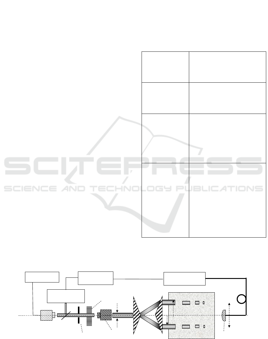
3.1 Measurement System
Figure 6 and Table 1 shows the structure of
measurement system and the specification of the
optical elements in our measurement system,
respectively.
A high power DPSS laser was introduced, and the
pulsed beam was used to increase the efficiency of
non-diffractive effect in random media. An ND filter
was used to adjust the optical intensity. A beam
expander and a pair of axicon prisms helped to control
the thickness and the diameter of the annular beam.
To change the propagation distance, three sizes of
media tanks were used. The processed milk with
1.8% fat was chosen as the random media. The fat
particles in the milk have the scattering coefficient
similar with human tissue, so that we can model the
human tissue by adjusting the concentration of the
milk. The absorption in the milk solution is very weak,
which can be ignored to compare with the effect of
scattering. The combination of a collimate lens and a
multiple mode optical fiber made a narrow view angle
of 5.5mrad, which helped to catch up the forward
scattering light, and this combination was set on a
mechanical stage controlled by PC with the resolution
of 0.1mm at horizontal-axis. A photo multiplier tube
(PMT) was used as a detector to obtain the weak
optical signal through the random media, and a
sampling oscilloscope was used to monitor the pulsed
electric signal from PMT.
Table 1: Specification of the experiment system.
Light source
DPSS laser CryLas, 1Q532-1:
Wavelength: 532nm;
Pulse width: 2ns;
Peak power: 4.6kW;
Repetition: 15kHz.
Annular beam
converter
Axicon prims:
Zenith angle: 150° (±10′);
Diameter: 50.8mm;
Annular beam diameter range:
24mm~42mm
Random media
Media tank:
Material: Tempax glass;
Size: W*H*L
20cm*20cm*(10,20,30)cm;
Media:
Processed milk with 1.8% fat;
Fat size: 1.1µm;
Diluted range: 0.1%~1.0%;
Receiver
Optical elements:
Optical Fiber: Multiple mode
Diameter.: 50µm;
Collimate lens N.A.:0.55
View angle: 5.5mrad;
PMT:
Hamamatsu R-636;
Response time: 0.78ns
Sampling oscilloscope:
Agilent, DCA-J 86100C with
83484A module
Bandwidth: 50GHz
3.2 Result
In the three sets of experiments, the milk concentration
Figure 6: The experiment system to analyze light propagation characteristics in random media.
Optical fiber
Axicon prisms
Media tank
Sampling
Oscilloscope
Photo Multiplier
Tube
Power Supply
Photon Diode
DPSS Laser
Dilutedmilksolution
Glass Plate
ND Filter
Pin Hole
Beam Expander
R-r
R
r
Collimate Lens
Optimization of Non-diffractive Beam Propagation in Random Media Formed by Annular Beam
67

was set as 0.1%~1.0% in steps of 0.1%. The observed
waveforms were combined two parts. The first part
was an isotropic intensity distribution caused by
multiple scattering. This part covered in all of the
scattering angle. Another part was non-diffractive
effect as a small peak at the center on the waveform.
The width of the center peak is about 6mm. For
comparison of the waveform, first, the intensity of non-
diffractive beam at 20mm away from center was
normalized as 1. The non-diffractive effect was
evaluated by the intensity ratio between the center
intensity and the intensity at 3mm away from center,
where was the foot of the peak of non-diffractive beam.
3.2.1 Propagation Distance
In the first experiment, a propagation distance was set
as 10, 20 and 30cm by using the different media tanks.
Figure 7 shows the different non-diffractive beams
converted by the annular beams with the same ring
thickness, the diameter, and the different propagation
distances. The waveform of 10cm and 20cm
propagation were added 0.02 and 0.01 in intensities
respectively, to facilitate visualization. These three
non-diffractive beams at the different propagation
distance obtained maximum in the concentration of
0.4%, 0.6% and 1.0%. Figure 8 shows the intensity
ratio of the non-diffractive effect when the isotropic
intensity was subtracted. The center intensity ratios
were 1.8%, 1.2% and 0.85% at the propagation
distance of 10, 20 and 30cm, respectively. As we
considered the scattering particles act as lens, this
result shows the non-diffractive beam has a high
intensity in short distance propagation with high
concentration. It has the same tendency with the
calculated result shown in Fig. 5, the non-diffractive
beam had a high intensity in a short distance when a
lens effect with short focal distance was considered.
Figure 7: Scattering wave fronts of annular beam with
different distance (Diameter: 40mm, Thickness: 3mm).
Figure 8: Intensity ratio of non-diffractive beam against
propagation distance in random media.
Figure 9: Scattering waveforms of annular beam with
different thickness (Diameter: 40mm; Distance: 20cm).
3.2.2 Annular Beam Thickness
As the next experiment, the ring thickness of annular
beam was set as 3 and 6mm. Figure 9 shows the
difference between two non-diffractive beams
converted by the annular beams with the same
diameter and the same propagation distance but with
the different ring thickness. The waveform intensity
obtained by the annular beam of ring thickness of
3mm has been added 0.01 for visualization. In the
case of the annular thickness of 3mm, the width of the
main peak of the obtained waveform is narrower than
that of the case of 6mm. Both widths of the main
peaks are about twice of the thickness of the incident
annular beams. The two non-diffractive beams were
transformed in the concentration of 0.6%. The center
intensities ratios of the non-diffractive beams are
1.2% and 1.0%. This result shows the annular beam
with the narrow thickness would generate a narrow
width and a high intensity of the non-diffractive beam
in random media. These variation had agreement with
the numerical calculation in Fig.3.
1
1.02
1.04
1.06
1.08
1.1
1.12
-20 -15 -10 -5 0 5 10 15 20
Normalized intensity (a.u.)
Position (mm)
Distance 30cm 0.4%
Distance 20cm 0.6%
Distance 10cm 1.0%
0.4
0.6
0.8
1
1.2
1.4
1.6
1.8
2
0 1020304050
Intensity ratio of non-diffractive beam (%)
Propagation distance in random media (cm)
1
1.02
1.04
1.06
1.08
-20 -15 -10 -5 0 5 10 15 20
Normalized intensity (a.u.)
Position (mm)
Thickness 6mm 0.6%
Thickness 3mm 0.6%
PHOTOPTICS 2016 - 4th International Conference on Photonics, Optics and Laser Technology
68

3.2.3 Annular Beam Diameter
In the third experiment, annular beam diameter was
set as 24, 32 and 40mm, respectively. Figure 10
shows the non-diffractive beams converted by the
annular beams with the same ring thickness and the
same propagation distance but with the different
diameter. The waveform converted by annular beams
with the diameter of 24mm and 32mm were added
0.02 and 0.01 in intensity for visualization. The
center intensities were 3.7%, 2.9% and 1.2% higher
than the intensity around away from center, and the
widths of the main peaks are 5~6mm. Figure 11
shows the intensity ratio between the non-diffractive
beam and the main peaks widths against the diameter
of the annular beam. They show that the non-
diffractive beam with the high intensity would be
transformed at the low concentration of the random
media when the annular beam diameter is small, but
the width of the main peak was kept in around 5~6mm
when the ring thickness of the annular beam was
3mm. Comparing to the numerical calculation, the
width of main peak was considered to be twice of the
annular beam thickness. These results were coincided
with the theory numerical calculation in Fig.4.
4 CONCLUSIONS
In this study, we considered that the propagation
characteristics of the annular beam in air was
associated with its experimental results in the random
media. They showed agreement in non-diffractive
beam propagation characteristics. For the same
incident annular beam, the random media at a short
propagation distance with a high concentration could
generate a high intensity non-diffractive beam. And
Figure 10: Scattering waveforms of annular beam with
different diameters (Thickness: 3mm; Distance: 20cm).
Figure 11: Variation of intensity ratio and main peak width
of non-diffractive beam. (Thickness: 3mm; Distance:
20cm).
for the same random media, the annular beam with
the narrow thickness or the small diameter could
generate a high intensity non-diffractive beam. The
width of the non- diffractive beam would be twice of
the thickness of the annular beam. And the non-
diffractive effect was generated in the random media
and had the same tendency with its propagation in air.
The results of the calculation and the experiment were
coincide with each other.
In future, further analysis of annular beam
propagation in random media should be explained by
diffusion and scattering theory, and the mathematical
relationship between non-diffractive beam waveform
and parameters such as the ring thickness or the
diameter of the annular beam should be cleared up.
REFERENCES
Shiina T., Ito M., Okamura Y., 2007. Long Range
Propagation Characteristics of Annular Beam, Optics
Communications, Vol.279, 159-167.
Aruga T., Li S., 1999. Super High Resolution for Long-
Range Imaging, Appl. Opt. 38, 2795-2799.
Craig F. Bohren, Donald R. Huffman, 1998. Absorption
and Scattering of Light by Small Particles. N.Y., Wiley
InterScience.
Profio A., 1989. Light Transport in Tissue, Appl. Opt. 28
(12), 2216-2222.
Ishimaru A., 1989. Diffusion of Light in Turbid Material,
Appl. Opt. 28 (12), 2210-2215.
Durian D., Weitz D., Pine D., 1991. Multiple Light-
Scattering Probes of Foam Structure and Dynamics,
Sience, Vol.252, 686-688.
Voelz D., Xiao X., 2009. Metric for Optimizing Spatially
Partially Coherent Beams for Propagation through
Turbulence, Opt. Eng. 48(3), 036001.
1
1.02
1.04
1.06
1.08
1.1
1.12
1.14
-20 -15 -10 -5 0 5 10 15 20
Normalized intensity (a.u.)
Position (mm)
Diameter 40mm 0.6%
Diameter 32mm 0.6%
Diameter 24mm 0.5%
0
1
2
3
4
5
6
7
8
9
10
1.0%
1.5%
2.0%
2.5%
3.0%
3.5%
4.0%
16 24 32 40 48
Diameter of main peak (mm)
Intensity of ratio of non-difractive beam (a.u.)
Diameter of annular beam (mm)
Ratio of non-diffractive beam (Experiment)
Ratio of non-diffractive beam (Calculation)
Diameter of main peak (Calculation)
Diameter of main peak (Experiment)
Optimization of Non-diffractive Beam Propagation in Random Media Formed by Annular Beam
69

Chen Y., Cai Y., Eyyuboglu H., Baykal Y., 2008.
Scintillation Properties of Dark Hollow Beams in a
Weak Turbulent Atmosphere, Appl. Phys. B. 90, 87-92.
Eyyuboglu H., Yenice Y., Baykal Y., 2006. Higher Order
Annular Gaussian Laser Beam Propagation in Free
Space, Opt. Eng. 45(3), 038002-1-038002-8.
Rao R., 2008. Statistics of the Fractal Structure and Phase
Singularity of a Plane Light Wave Propagation in
Atmospheric Turbulence, Appl. Opt. 47, 269–276.
Gercekcioglu H., Baykal Y., Nakiboglu C., 2010. Annular
Beam Scintillations in Strong Turbulence, J. Opt. Soc.
Am. A, 27(8), 1834-1839.
Baykal Y., 2005. Log-amplitude and Phase Fluctuations of
Higher-order Annular Laser Beams in a Turbulent
Medium, J. Opt. Soc. Am. A, 22, 672-679.
Eyyuboglu H., Cil C., 2008. Beam Wander of Dark Hollow,
Flat-topped and Annular Beams, Appl. Phys. B, 93,
595-604.
Shiina T., Yoshida K., Ito M., Okamura Y., 2005. In-line
Type Micro Pulse Lidar with Annular Beam -
Theoretical Approach, Appl. Opt. 44 (34), 7467-7473.
Peng Z., Shiina T., 2011. Analysis of Annular Light
Propagation Characteristics in Random Media, Asia
Communications and Photonics, Vol. 8311.
Fedotowsky A., Lehovec K., 1974. Optimal Filter Design
for Annular Imaging, Appl. Opt. 13(12), 2919–2923.
Scott G. McArdle N., 1992. Efficient Generation of Nearly
Diffraction-free Beams Using an Axicon, Opt. Eng.
31(12), 2640-2643.
Aruga T., 1997. Generation of Long-range Non-diffracting
Narrow Light Beams, Appl. Opt. 36, 3762-3768.
Aruga, T., Li S., Yoshikado S., Takabe M., and Li R., 1999.
Nondiffracting Narrow Light Beam with Small
Atmospheric Turbulence-influenced Propagation,
Appl. Opt. 38 (15), 3152-3156.
Kono K., Irie M., Minemoto T., 1997. Generation of Nearly
Diffraction-Free Beams Using a New Optical System,
Optical Review, 4 (3), 423-428.
PHOTOPTICS 2016 - 4th International Conference on Photonics, Optics and Laser Technology
70
