
GSM Model Construction from Enterprise Models
Imen Jellali
1
, Mounira Ben Abdallah
1
, Nahla Zaaboub Haddar
1
and Hanêne Ben-Abdallah
2
1
Mir@cl Laboratory, University of Sfax, Sfax, Tunisia
2
Mir@cl Laboratory, King Abdulaziz University, Jeddah, Saudi Arabia
Keywords: Business Entity, Business Process, GSM Model, Enterprise Models.
Abstract: Business process analysis is an essential tool to assess how well a business is meeting its goals. However,
the process analysis phase may fail in some cases because it focuses either on the data perspective and
ignores business activities, or on the functional and behavioral perspectives of the business process and
overlooks the data. Indeed, traditional analysis approaches are based on models that do not represent all of
these business process perspectives together. Recently, Entity-Centric Modeling has been proposed as a
promising approach for the design of business processes based on so-called business entities. It aims to
bring together business goals, business operations and business data in a natural way. In this paper, we
propose a method to design an enterprise view based on business entities in order to bring together data and
processes in a coherent and consistent way. The constructed view provides for an integrated analysis of data
and processes. Our method takes as input a domain class diagram of the enterprise information system and a
BPMN model representing its business process model, and it constructs a business entity model using the
Guard-Stage-Milestone (GSM) language.
1 INTRODUCTION
Business process (BP) analysis is an essential tool
that assesses how well a business is meeting its
goals. It helps an organization to improve its
activities in order to reduce overall costs, provide
more efficient use of scarce resources, and offer high
quality services to its customers. To be efficient, the
process analysis phase must focus on three
interdependent perspectives: the data, the functional
and behavioral perspectives of the BP. However,
traditional analysis approaches are based on models
that do not represent all of these perspectives
(Leymann et al., 2002) (van der Aalst et al., 2003);
by focusing on some perspectives only, these
analysis approaches may hinder the analysis of some
business subjects. For example, by analyzing the
activities of a product delivery process without
including pertinent information about the business
objects manipulated by these activities, it is not
possible to find out the activities which are
responsible of delays in the delivery time of a given
product category. Such analysis results require the
integration of the processes with the data.
Recently, a new concept called business entity
(BE) was proposed in the information system
domain. It aims to bring together business goals,
business operations and business data in a natural
way. A BE is a key business-relevant dynamic
conceptual object that is manipulated in the
information system. It is created, evolved, and
archived as it passes through the operations of an
enterprise (Nandi et al., 2010). A BE is well defined
through its behavior, its structure, as well as the
business activities that manage it. Indeed, a BE
model includes both an information model showing
its structure, and a lifecycle model that describes
how, when, and by whom tasks can be invoked and
performed on the BE. For instance, in a product
delivery management business domain, a product
delivery is a BE type, whose information model
would include attributes for product ID, sender,
recipient, delivery method, arrival times, delivery
time, and billing information; its lifecycle model
would include the multiple ways that the product
could be delivered and paid for.
Several approaches have been proposed to model
BEs, which we classify into two categories:
Approaches starting from scratch (Liu et al., 2007)
(Bhattacharya et al., 2009) (Nandi et al., 2010) and
others based on operational enterprise systems
(Kumaran et al., 2008) (Nooijen et al., 2013)
(Popova and Dumas, 2013). The first category of
approaches starts with specifying the stakeholder
100
Jellali I., Ben Abdallah M., Zaaboub Haddar N. and Ben-Abdallah H..
GSM Model Construction from Enterprise Models.
DOI: 10.5220/0005573301000108
In Proceedings of the 12th International Conference on e-Business (ICE-B-2015), pages 100-108
ISBN: 978-989-758-113-7
Copyright
c
2015 SCITEPRESS (Science and Technology Publications, Lda.)

needs in order to define the BEs. The approaches in
this category are time consuming, costly and they do
not exploit the enterprise existing knowledge
represented within its operational systems. To
overcome these limitations, the second category of
approaches exploits this knowledge (workflow logs,
databases...) to model business entities. Most of
them generate entity models from event logs, i.e.
recorded executions of the process. However, the
entity model generation from event logs faces many
challenges (van der Aalst and Weijter, 2004), e.g.,
event logs incompleteness and noise such as
exceptions and logging errors. Some other
researches assume a structured data source (i.e.
database) to be given as additional input for BE
lifecycle discovery cf. (Nooijen et al. , 2013). This
data source contains information about the events
that have occurred on data in past process
executions. Usually, this information is present as
timestamps in the records of the data source. But,
this data source may be incomplete because the data
dependencies were created at the application layer
and are not documented in the data source.
In this paper, we propose to bring data and
processes together in a coherent and consistent way
through the design of an enterprise view based on BE
models. The obtained artifacts form an integrated view
of data and processes (through BEs), that enables to
analyze facts that cannot be analyzed by data and
process warehouses taken separately. In addition, this
integrated view increases the scope of reuse of process
models, since the process is refactored around business
entities. It also leads to agility in design, as the changes
can be localized in process fragments without affecting
other parts of the design (Nandi et al., 2010).
To construct BE models, we make use of
conceptual enterprise models. These latter are usually
available in enterprises that comply with standards, and
they should be aligned with the operational systems.
Without loss of generality, we suppose that these
models are specified with the standard languages
BPMN (BPMN, 2011) and UML (Unified Modeling
Language, 1997). We specify BE models with the
standard BE specification language Guard-Stage-
Milestone (GSM) (Hull et al., 2010) (Hull et al., 2011).
More specifically, our GSM model construction
method takes as input a domain class diagram of the
enterprise IS and a BPMN model representing its BP
models. It operates in three steps: In the first step, it
runs through the process model to discover all BEs
handled by the business activities. Afterwards, in the
second step, it constructs, for each identified BE, its
lifecycle model. Finally, in the third step, it builds the
BE information models based on the domain class
diagram.
This paper is organized as follows. In Section 2, we
present the concept of BE and the standard BE
specification language GSM. In Section 3, we present
related works to place our contributions in their
context. In Section 4, we present our method to
construct a GSM model from enterprise IS and process
models. Finally, in Section 5, we conclude and present
future works.
2 BUSINESS ENTITIES AND GSM
A BE is a key business-relevant dynamic object
manipulated in the information system. It is created,
evolved, and archived as it passes through the
operations of an enterprise (Nandi et al., 2010). A BE is
characterized by its structure and its lifecycle. Most of
the existing works on BE modeling focus on the
lifecycle model and ignore the BE structure. The
formalism used to model the BE lifecycle is based on
variants of finite state machines (Kumaran et al., 2003)
(Nandi et al., 2010) (Nigam and Caswell, 2003).
Recently, the Guard-Stage-Milestone (GSM) language
(Hull et al., 2010) (Hull et al., 2011) has been proposed
by the Object Management Group (OMG) as a
standard for BE specification.
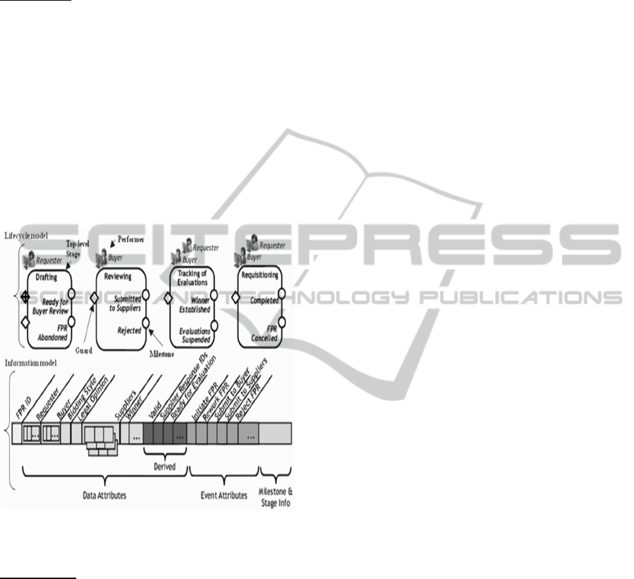
In GSM, a BE includes both an information model
and a lifecycle model (cf. Figure 4). The lifecycle
model of a BE in GSM specifies its progression stages.
A stage is a cluster of activities that might be
performed for, with, and/or by an entity instance, in
order to achieve one of the operational objectives of
that stage called milestone. A stage can be complex
(contain sub-stages) or atomic. The transition from one
stage to another is conditional due to the sentries used
in guards and milestones. These sentries control when
stages open and when milestones are achieved or
invalidated. Achieving a milestone m of some stage
generates an event MAchieved() that can be used in the
guard of another stage. This way, the execution of
stages can be ordered. The GSM informational
perspective of a BE is modeled using the information
model. This model captures all of the business-relevant
data about a BE. It is broken into two categories. The
data attributes hold business-relevant data about the
progress of an entity instance. The status attributes
hold information about the current status and update
time of all milestones (true or false) and all stages
(open or closed).
Figure 1 shows an example of a business entity,
called "Fixed Price Request entity type", using the
GSM notation.
GSMModelConstructionfromEnterpriseModels
101
In the following, we give a formal definition of a
BE within GSM (Hull, et al., 2011).
Definition 1: A BE type (or simply a BE) has the form
(R, Att, Stg, Tsk, Mst, Str, Per, Lc) where:
• R is the name of the BE and it is often used to
refer to the BE itself.
• Att is the set of attributes of this BE. This set is
further split into a set of attributes Att
data
and a set
of status attributes Att
status
.
• Tsk is a set of tasks that change the attributes of
the BE.
• Stg is the set of stage names.
• Mst is the set of milestone names.
• Str is a set of sentries.
• Per is a set of task performers.
• Lc is the BE lifecycle model.
Figure 1: A business entity using GSM notation (Hull et
al., 2010).
Definition 2: A GSM model is a set of n BEs with
the form (
,
,
,
,
,
,
,
), where i
∈
[1..n] and all BE type names R
i
are
pair wise distinct.
3 RELATED WORKS
The works related to our approach involve two
domains: analysis of business processes (BPs) and
business entity models. Works on analysis of BPs
can be classified into three categories: approaches
that focus on the data perspective and ignore
business activities (Golfarelli, 2010) (P. Giorgini,
2005), those which consider the functional and
behavioral perspectives of BPs and overlook data
(List, 2000) (Sturm, 2012), and those which propose
to improve the BP analysis by adding additional
information, such as business goals or organizational
structure, during the analysis or the construction
phase (Antonio Ferrández, 2014) (Alejandro Matéa,
2014) (Stefanov, 2006) (Chowdhary et al., 2006)
(Shahzad, 2012). Indeed, in (Antonio Ferrández,
2014), the authors propose to integrate the DW
structured data with the external unstructured data
obtained by Question Answering (QA) techniques.
The unstructured data are extracted from different
external sources (e.g. Big Data, blogs, social
networks, etc.). The integration is achieved through
the presentation of the data returned by the DW and
the QA systems into dashboards that allow the user
to handle both types of data. Moreover, the QA
results are stored in a persistent way through a new
DW repository in order to facilitate comparison of
the obtained results with different questions or even
the same question with different dates. In (Alejandro
Matéa, 2014), the authors propose an i* profile for
DWs that considers user goals in a DW model in
order to increase the error correction capability of
the analysis, and to make complex models easier to
understand by DW developers and non expert users.
In (Stefanov, 2006), the authors propose an approach
that weaves enterprise models (organizational
structure and business goal model) to the data
warehouse to make enterprise context knowledge
easily accessible and to improve the data
interpretation for the business users. In (Chowdhary
et al., 2006), the authors present a model driven data
warehousing approach to bridge the gap between BP
models and data warehouse models. This solution
defines a business process warehouse model
(BPWM) that represents an extension of the existing
BPM models to represent data warehouse model
elements and then transforms the BPWM model to a
physical data warehouse schema. This approach
enables the alignment of the data warehouse with the
BPs. In (Shahzad, 2012), the author proposes a
process warehouse consisting of two parts: a stable
and a case-specific part. The stable part stores
information about goal structure and its relationship
with process warehouse structure, such as
satisfaction conditions, indicators, and goal related
dimensions. The case-specific part captures the
dimensions and facts about a process, which are
essential for performance analysis of BPs. This part
is dynamic in the sense that a data model is
developed for each process, i.e. the dimensions and
facts identified for a process can be different from
those of another process.
ICE-B2015-InternationalConferenceone-Business
102

The concept of BE has been proposed in the
early 2000 as a means to have an integrated view of
BPs and data. Since then, few approaches have been
proposed to model BEs. Some works start from
scratch and propose methods to construct the BE
models (Liu et al. 2007) (Bhattacharya et al., 2009)
(Nandi et al., 2010). The proposed methods start
from stakeholder requirements to identify the BEs.
Then, for each identified BE, they develop the
corresponding lifecycle model that the entity moves
through, including the key stages of the processing
of the entity and how they are or might be
sequenced. However, those methods are time
consuming and demand consulting skills. Moreover,
they do not exploit the existing models of the
enterprise.
Other works start from existing enterprise
operational systems (workflow logs, databases ...) to
model BEs (Kumaran et al., 2008) (Nooijen et al.,
2013) (Popova and Dumas, 2013). In (Kumaran et
al., 2008), the authors derive an algorithm that
generates a BE model from a BP model to bridge the
gap between these models and show the duality
between them. In (Nooijen et al., 2013), the authors
present an automatic technique for discovering BE
models from a structured data source that stores
process execution information of a data-centric
system. In (Popova and Dumas, 2013), the authors
propose a method for translating process models,
represented by Petri Net models, into lifecycle
models of BEs. The formalisms used to model BEs
in these works are variants of finite state machines
(Kumaran et al., 2003) (Nandi et al., 2010) (Nigam
and Caswell, 2003) and the Guard-Stage-Milestone
(GSM) model (Hull et al., 2010) (Hull et al., 2011)
(Nigam and Caswell, 2003). However, GSM is a
standard language. It is more declarative than the
finite state machine variants, and supports hierarchy
and parallelism within a single artifact instance. It
reflects the way stakeholders think about their
business. Furthermore, its hierarchical structure
allows for a high-level, abstract view on the
operations while still being executable. It supports a
wide range of process types, from the highly
prescriptive to the highly descriptive.
All the works on modeling BEs focus on the
lifecycle model of the BE and neglect their
informational and organizational perspectives. They
generate the lifecycle models starting only from
event logs, which contain recorded executions of the
process. However, the discovery of lifecycle models
from both, event logs and structured data source
faces many challenges. Indeed, event logs can be
incomplete and may not model all allowable
behaviors of the BP. Indeed, the behavior of the
process present in the event logs depends on the
process history. In addition, the event logs may
contain noise such as exceptions and logging errors.
4 GSM CONSTRUCTION
METHOD
Our GSM construction method takes as input two
conceptual models: a class diagram D and a BPMN
model P and returns as output a GSM model G. It is
composed of three main steps: BE identification
Figure 2: A BPMN model for the Cash Withdrawal process.
GSMModelConstructionfromEnterpriseModels
103
which identifies the BEs in P, BE lifecycle
construction which constructs, for each identified
BE, its lifecycle model, and BE information model
construction which constructs the information
models of the business entities.
Before detailing those steps, we start by
presenting an example used to illustrate our method.
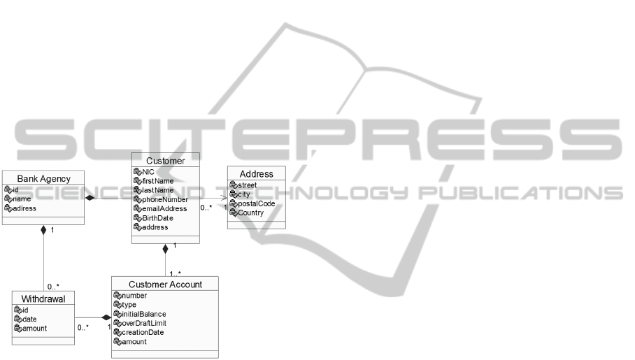
We consider a cash withdrawal process (cf. Figure
2) and a class diagram representing the business
objects involved in this process (cf. Figure 3). The
process starts when the customer comes to the bank
agency, fills a withdrawal request form, and submits
it to the receptionist. The latter checks the customer
identity and confirms that the declared bank account
exists. If not, the withdrawal is refused. Otherwise,
the receptionist checks if the balance of the customer
account is higher than the requested amount. If not,
the withdrawal is refused. Otherwise, the customer
account is updated and cash is delivered.
Figure 3: A class diagram of the Cash Withdrawal.
4.1 Business Entity Identification
BEs are the objects handled by BPs. They may be
consumed, changed or created by the process
activities. In a BPMN model, they are represented
by the concept of Data Object. A data object is
associated with the activity which manipulates it
using an association relation. Hence, for each data
object of P, we create a BE having the same name as
the data object. This step needs the stakeholder
intervention to validate the generated set of BEs.
Indeed, the stakeholder may consider that some of
these BEs are useless in the view to be constructed,
e.g., if the view is intended to be used for transaction
analysis, some BEs not representing transactions are
not interesting.
Applied to our Cash Withdrawal process of
Figure 2, this step yields two business entities:
withdrawal request and customer account.
4.2 Entity Lifecycle Construction
The second step of our method constructs the
lifecycle model for each business entity identified in
the first step. It starts with creating the top-level
stages of each BE. Then, it creates embedded stages
and their associated guards and milestones.
4.2.1 Stage Construction
A stage of a BE in the GSM model corresponds to a
named activity related to this BE. That is, it can be
seen as a state of the lifecycle of the BE in which
some activities are executed. A stage can be either
complex or atomic. Complex stages contain one or
more sub-stages. Atomic stages cannot have sub-
stages, but are placeholders for tasks. Atomic stages
can contain one or more tasks, depending on task
types. Hence, a top level stage matches with one of
the states of the Data Object corresponding to the
BE. In the business process P, for each state of a
data object (that is represented as a text between
brackets under the data object), we create a BE top
level stage.
In our example, the entity withdrawal request
has three states: created, refused and accepted. So, in
its lifecycle model, we create three top-level stages
"Creating", "Refusing" and "Accepting" (cf. Figure 4).
Note that the sequence of activities responsible
of a state change of each data object is used to create
the sub-stages of the top level one in the GSM
model. We identify the sub-stages depending on the
number of activities of the sequence and their types:
1- If there is one activity in this sequence and it
is a task, then we create a new task associated with
the corresponding top-level stage. In our example,
the task "Refuse withdrawal" of the withdrawal
process is responsible of the change of the state of
the entity withdrawal request. So, we create a task
"Refuse withdrawal" and we associate it with the
top-level stage "Refusing" in the GSM model.
2- If the sequence is composed of one sub-
process or of more than one activity, then we go
through the sequence and we create sub-stages
depending on the type of the crossed activity. If an
activity is a sub-process, then we consider the
corresponding top-level stage as a complex stage.
For each task of this sub-process, we create a new
atomic stage and we associate this task with the
created stage. The obtained atomic stages are
embedded as sub-stages in the top-level one. But, if
an activity is a task, then we proceed as explained in 1.
In our example, the sequence of activities which
trigger the creation of the entity withdrawal request
ICE-B2015-InternationalConferenceone-Business
104

is composed of two activities: "Fill withdrawal
form" and "Submit withdrawal request". Thus, we
create two atomic stages "Filling" and "Submitting".
Afterwards, we associate the tasks: "Fill withdrawal
form" and "Submit withdrawal request" respectively
with the created stages. These stages are embedded
in the top-level stage "Creating".
4.2.2 Milestone Construction
A milestone in a GSM lifecycle model corresponds
to a business relevant objective or goal that can be
achieved. It is always attached to exactly one stage,
i.e. each stage is equipped with milestones to
determine when its goals are achieved. So, for each
stage in the new GSM model, we create milestone
that indicates the achievement of the corresponding
stage. For example, in our example, we create a new
milestone called "Filled" for the stage "Filling" (c.f.
Figure 4).
4.2.3 Guard and Sentry Construction
A guard specifies a condition associated to a single
stage and indicates when a stage becomes active, i.e.
when the guard becomes true, the associated stage is
opened. The expression of a guard is called a sentry.
We identify the guard of a stage depending on the
direct predecessor of the corresponding activity in
the BP model P. Possible cases are the following
ones:
1. If the predecessor is the start event, then we
create a new guard with the sentry "initiating" and
we associate it with the corresponding top-level
stage (cf. Figure 4).
2. If the predecessor is an intermediate event,
then we create a new guard and we associate it with
the corresponding stage. Then, we match the event
with the sentry of his guard. For instance, in our
example (cf. Figure 4), we create a new guard with
the sentry "on DeliveredAchieved" for the
intermediate message event which comes before the
activity "Receive cash". Then, we associate this
guard with the stage "Receiving".
3. If the predecessor is an activity, we create a
new guard with its sentry and we associate it with
the corresponding stage.
In our example, the activity "Fill withdrawal
form" is the direct predecessor of "Submit request
withdrawal". So, we create a new guard with the
sentry "on FilledAchieved()" and we associate it
with the stage "Submitting".
4. If the predecessor of the considered activity is
a gateway, we generate a combination of conditions.
The combining operator corresponds to the gateway
type (for AND- and XOR-splits and joins). The
obtained expression is the sentry of the guard of the
stage under construction. This sentry may be
complex especially when there is a sequence of
gateways preceding the considered activity. So, we
apply the procedures proposed in (Popova and
Dumas, 2013) to decompose the sentry into multiple
shorter and more intuitive sentries, which are then
assigned to separate guards of the corresponding
stage.
When applying those rules to our running
example, we obtain a new guard, called on
NotAuthenticatedAchieved(), for the gateway which
precedes the activity Check balance. Then, we
associate this guard with the top-level stage
"Refusing". Also, we create a new guard called on
AuthenticatedAchieved() and we associate it with the
stage "Checking" (cf. Figure 4).
4.2.4 Performer Construction
In a GSM model, a performer can perform human
tasks that are invoked from within atomic stages. On
the other hand, pools and lanes are participants in a
BPMN model. They are viewed as process
containers since they are the performers of all the
activities of the process they contain. In this sense, a
pool or a lane is equal to a performer. So, when the
BPMN model has pools without any specification of
lanes, then we create a new performer for each pool.
But when lanes are specified in the BPMN model,
then we create a performer for each lane. The new
performers are associated with the corresponding
atomic stages.
In our example, two pools are specified in the
BPMN model. So, we create two performers
"Customer" and "Bank agency" for those pools.
Then, we associate the performer "Customer" with
the stages "Filling" and "Submitting" of the BE
Withdrawal request (cf. Figure 4).
4.3 Entity Information Model
Construction
The third step of our method is to construct the
information model of each BE identified in the first
step. We start with constructing the information
model from the class diagram D. However, the
classes of this diagram contain only data attributes,
but no status attributes as in an information model.
So, we add status attributes for each constructed
information model, as explained below.
GSMModelConstructionfromEnterpriseModels
105
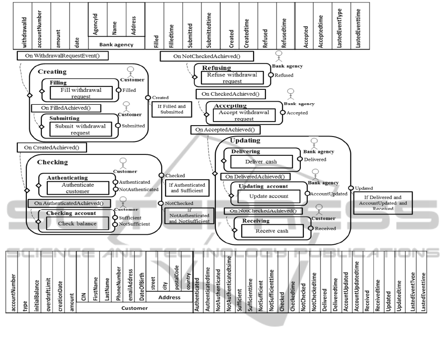
Figure 4: GSM model of cash Withdrawal process.
4.3.1 Data Attribute Construction
In the first step of our view construction method, we
have associated BEs to data objects of the enterprise.
Since a data object is an artifact of the IS of the
enterprise, it corresponds necessarily to a class in its
domain class diagram D. So, we construct the data
attributes of the information model of each BE from the
class attributes of the corresponding class of D.
For instance, in our example, the BE class
Customer account is made up of atomic attributes. So,
we create a new data attribute for each one:
AccountNumber, Type, initialBalance, overDraftLimit,
creationDate, amount (c.f. Figure 4).
Afterwards, we deal with the classes related to the
BE class. For each class c of these classes, if it does not
correspond to a BE, we associate it with a new data
attribute in the information model of the BE. This
attribute has c as type.
In our example, the BE class Customer account is
related to the class Customer (cf. Figure 3). So, we add
a new data attribute called customer of type Customer
to the information model of this BE. (cf. Figure 4).
4.3.2 Status Attribute Construction
In this step, we add status attributes to the information
model of each BE. For each BE, we add a status
attribute that stores the most recently incoming event.
Also, we add another status attribute for the logical
timestamp of this event. Then, for each milestone of a
stage of the BE, we add two attributes. The first
attribute holds a logical value (true or false) that
corresponds to the value of the milestone (achieved or
not achieved). The second attribute gives the logical
timestamp of the value change of the milestone.
In our example, we add the status attributes
LastEventType, LastEventTime. In addition, we add the
attributes Accepted and Acceptedtime for the milestone
Accepted of the stage Accepting of the entity
Withdrawal request (cf. Figure 4).
5 CONCLUSIONS
In this paper, we presented a method for constructing a
view above operational business model to allow for
analyzing facts that cannot be analyzed by using data or
ICE-B2015-InternationalConferenceone-Business
106

process warehouses taken separately. This view is
based on the concept of BE which integrates data and
process in a natural way. Our method takes as input a
BP model and a domain model. It identifies business
entities and constructs their lifecycle and information
models using the standard language GSM. Unlike
works starting from scratch (Liu et al. 2007)
(Bhattacharya et al., 2009) (Nandi et al., 2010), our
method reuses enterprise models to design BEs. Also, it
constitutes an alternative to constructing BEs lifecycles
from event logs (Kumaran et al., 2008) (Popova and
Dumas, 2013) and structured data source (Nooijen et
al., 2013) which faces many challenges as explained in
Section 3.
Since our method exploits all knowledge on
business perspectives (functional, organizational,
behavioral and informational perspectives) represented
within these models, the generated BEs are completely
defined and all their perspectives are covered.
Currently, we are defining a method to identify
elements of a new concept of warehouse, the BE
warehouse. This warehouse stores BEs and
consequently offers analyses based on the correlations
among the data, functional and behavioral aspects of
business processes.
REFERENCES
Alejandro Matéa, J. T. (2014). Adding semantic modules
to improve goal-oriented analysis of data warehouses
using I-star. Journal of Systems and Software, 88, 102-
111.
Antonio Ferrández, A. M.-A. (2014, December 23). A
framework for enriching Data Warehouse analysis
with Question Answering systems. Journal of
Intelligent Information Systems.
Bhattacharya, K., Hull, R., & Su, J. (2009). A Data-centric
Design Methodology for Business Processes. (J.
Cardoso, & W. van der Aalst, Eds.) Handbook of
Research on Business Process Management.
Business Process Model and Notation (BPMN). (2011).
Retrieved from http://www.omg.org/spec/BPMN/2.0.
Chowdhary, P., Mihaila, G., & Lei, H. (2006). Model
Driven Data Warehousing for Business Performance
Management. IEEE International Conference on e-
Business Engineering ICEBE '06', 483 - 487.
Golfarelli, M. (2010). From User Requirements to
Conceptual De- sign in Data Warehouse Design. Data
Warehousing De- sign and Advanced Engineering
Applications: Methods for Complex Construction, p. 1.
Hull, R., Damaggio, E., De Masellis, R., Fournier, F.,
Gupta, M., Heath III, F. (., et al. (2011). Business
Artifacts with Guard-Stage-Milestone Lifecycles:
Managing Artifact Interactions with Conditions and
Events. Conf. on Distributed Event-Based Systems
DEBS 2011, 51-62.
Hull, R., Damaggio, E., Fournier, F., & Gupta, M. (2010).
Introducing the guard-stage-milestone approach for
specifying business entity lifecycles. Proc. of 7th Intl.
Workshop on Web Services and Formal Methods (WS-
FM 2010).
Kumaran, S., Liu, R., & Y. Wu, F. (2008). On the Duality
of Information-Centric and Activity-Centric Models of
Business Processes. 20th International Conference
CAiSE, Advanced Information Systems Engineering,
5074, 32-47.
Kumaran, S., Nandi, P., Heath, T., & Bhaskaran, K.
(2003). ADoc-oriented programming. Symposium on
Applications and the Internet (SAINT), 334–343.
Leymann, f., Roller, D., & Schmidt, M.-T. (2002). Web
services and business process management. IBM
Systems Journal, 41 (2), 198–211.
List, B. S. (2000). The Process Warehouse: A Data
Warehouse Approach for Multidimensional Business
Process Analysis and Improvement. DW2000.
Liu, R., Bhattacharya, K., & Wu, F. Y. (2007). Modeling
business contexture and behavior using business
artifacts. CAiSE, 4495, 324-339.
Nandi, P., König, D., Klicnik, V., Claussen, S., Moser, S.,
Kloppmann, M., et al. (2010, April). Data4BPM, Part
1: Introducing Business Entities and the Business
Entity Definition Language (BEDL). Retrieved from
http://www.ibm.com/
developerworks/websphere/library/.
Nigam, A., & Caswell, N. (2003). Business artifacts: An
approach to operational specification. IBM Systems
Journal, 42
(3), 428–445 .
Nooijen, E. H., van Dongen, B. F., & Fahland, D. (2013).
Automatic Discovery of Data-Centric and Artifact-
Centric Processes. (M. La Rosa, & S. Pnina, Eds.)
Business Process Management Workshops, 132, 316-
327.
P. Giorgini, S. R. (2005). Goal Oriented Re- quirement
Analysis for Data Warehouse Design. DOLAP’05, 45,
pp. 47-56.
Popova, V., & Dumas, M. (2013). From Petri Nets to
Guard-Stage-Milestone Models. (M. La Rosa, & P.
Soffer, Eds.) Business Process Management
Workshops, 132 (978-3-642-36284-2), 340-351.
Shahzad, M. K. (2012). Improving Business Processes
using Process oriented Data Warehouse. Doctoral
Dissertation, Royal Institute of Technology,
Stockholm, Sweden.
Stefanov, V. (2006, June). Bridging the Gap between Data
Warehouses and Organizations. In Proceedings of
Workshops and Doctoral Consortium, 18th
Conference on Advanced Information System
Engineering (CAiSE'06), pp. 1160-1167.
Sturm, A. (2012). Supporting business process analysis via
data warehousing. Journal of Software: Evolution and
Process, Special Issue: Business Process Modeling,
Development and Support, 24 (3), 303-319.
GSMModelConstructionfromEnterpriseModels
107

Unified Modeling Language. (1997). Retrieved 05 22,
2015, from Object Management Group:
http://www.uml.org/
van der Aalst, W., & Weijter, A. (2004). Process mining: a
research agenda. Computers in Industry - Special
issue: Process/workflow mining, 53 (3), 231–244.
van der Aalst, W., ter Hofstede, A., Kiepuszewski, B., &
Barros, A. (2003). Workflow patterns. Distributed and
parrallel databases, 14 (3), 5–51.
ICE-B2015-InternationalConferenceone-Business
108
