
Design of Mobile Microrobots with Thermomechanical Actuators
N. N. Bolotnik, V. G. Chashchukhin, V. G. Gradetsky, D. V. Kozlov, I. P. Smirnov,
A. N. Sukhanov and A. A. Zhukov
Institute for Problems in Mechanics of the Russian Academy of Sciences, Moscow, Russia
Keywords: Thermomechanical Actuator, Mobile Microrobot, Motion Phases, Acting Forces, Robot Structure,
Mechanical System Design.
Abstract: A design concept of a legged mobile microrobot that utilizes thermomechanical actuators is discussed. The
forces and torques acting on the legs of the microrobot are identified and analyzed. The phases of motion,
conditions of motion, and sequences of operations are defined; the performance characteristics of the robots
are studied. A number of design schematics of the microrobot are presented and compared. The issues
related to the mechanical structure of the robots, as well as the content and amount of information required
by the measurement and control systems are considered. A modified thermomechanical actuator was
developed for the microrobot leg. The structure of the actuator involves a feedback sensor. The design
sketches of the inspector microrobot with an on-board micromanipulator based on the thermomechanical
actuator are proposed. Possible applications of the microrobot for aerospace planet missions are discussed.
This study was supported by the Russian Science Foundation (Grant #14-19-00949).
1 INTRODUCTION
Active investigations of moving microstructures
based on the thermomechanical principle of
operation have been performed for more than 30
years. Various prototypes were developed for
effective applications in robotics. Actuators with V-
grooves were proposed in (Erdem 2010; Wallace
2006; Zhukov 2012; Norton 2009; Ebefors, 1999;
Ebefors, 2000). Most of them are similar to the
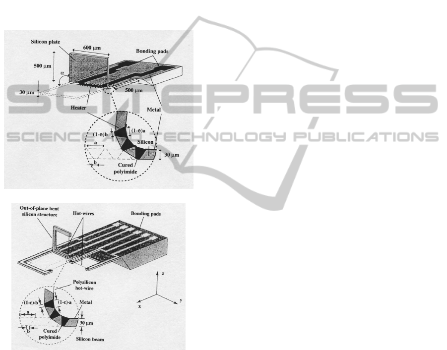
actuators considered in our study. In papers (Erdem
2010; Popa 2010), the creation of a MEMS hot-wire
three-dimensional structure based on a polyimide
joint with several V-grooves (Fig. 1) was discussed.
The electrical connection of the actuator to the
power supply and control units is implemented by
means of the metallic buses passing over the V-
grooves (Fig. 1, a, b). These buses transmit the
control signal to the actuator, which makes it rotate.
Such a structure illustrates the design of sensors
for measuring gas flow and moving microrobotic
platforms. In addition, scientific results related to the
prototype design were obtained in Japan (Ebefors,
1999) in the area of biomorphic structures that use
thermomechanical and electrostatic effects, in USA
Clark 2012 in the field of microrobots based on
thermomechanical actuators, as well as in other
countries (God-el-Hak 2002; Harc 2002).
Previous studies dealt with thermomechanical
devices involved in the design of the control system
for a miniature mirror utilized in aerospace systems
(Zhukov, 2014; Wallace, 2006; Zhukov, 2012).
Thermomechanical actuators for mobile microrobots
intended for space technology were proposed
(Zhukov, 2014). In a well-known mobile device
“Thermal-powered insect-like robot” (Erdem, 2010),
thermomechanical actuators are composed of two
polyimide layers with different temperature
coefficients of linear expansion. The robot can move
in four directions over a plane with a velocity of
3ft/hr. The disadvantage of this device is its
impossibility to move over stepped and slope
surfaces and a low velocity.
A stepping device “A walking silicon micro-
robot” is implemented on a silicon substrate and has
two rows of thermomechanical actuators with V-
grooves filled up with polyimide (Ebefors, 1999).
Among other devices, we can indicate “Microid
microrobot” (Clark, 2012) that combines
piezoelectric elements and “Microcrawler and
conveyor robot” (Popa, 2010) that is installed on a
platform with controller and power supply units.
Both robots have problems when moving along
rough surfaces. Attempts were made to improve
characteristics of the termomechanical actuator
(Bolotnik, 2015; Gradetsky, 2010; Kozlov 2010;
252
N. Bolotnik N., G. Chashchukhin V., G. Gradetsky V., V. Kozlov D., P. Smirnov I., N. Sukhanov A. and A. Zhukov A..
Design of Mobile Microrobots with Thermomechanical Actuators.
DOI: 10.5220/0005527602520258
In Proceedings of the 12th International Conference on Informatics in Control, Automation and Robotics (ICINCO-2015), pages 252-258
ISBN: 978-989-758-123-6
Copyright
c
2015 SCITEPRESS (Science and Technology Publications, Lda.)
Korpukhin, 2011). Other studies were carried out to
develop high-perfomance unimorph actuators based
on electrostrictive copolymers (Xu, 2002) and
microthermophotovoltaic systems (Yang, 2002). In
addition, sensor materials and measurement systems
were presented for extreme environments such as
high temperature, high pressure, toxicity, nuclear
radiation, and electromagnetic pulses (Fahrner,
2001; Kondon, 1997). The question arises on how to
design microrobots that possess additional
possibilities. In our paper we discuss the following
issues:
a)
b)
Figure 1: View of MEMS polyimide joint structure
(Ebefors 1999). a) MEMS triple hot-wire; b) Isometric
view of a three-dimensioned structure based on polyimide
joint with three V-grooves.
- application of a new modified
thermomechanical actuator for microrobot design;
- identification of the forces and torques
acting on the legs of a mobile microrobot;
- analysis of motion phases and schematics of
mobile microrobots.
Solving these problems may help overcome the
disadvantages mentioned above and improve the
functional parameters of mobile microrobots.
2 MODIFIED
THERMOMECHANICAL
ACTUATOR FOR
MICROROBOT LEG
A modified thermomechanical actuator was
developed (Zhukov 2014; Zhukov, 2012; Bolotnik,
2015; Gradetsky, 2010; Kozlov, 2010; Korpukhin,
2011) to improve the functional characteristics of
microrobots and enable using them in outer space. A
microrobot leg based on this type of actuator
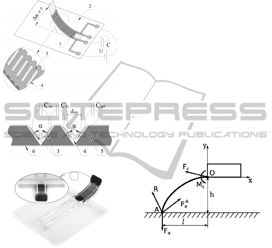
contains the following components (Fig. 2):
Polyimide (4) lies mostly in n grooves between
neighboring silicon elements 5 (Fig. 2, a, b, c).
When an electrical pulse is applied to the silicon
elements, the polyimide layer undergoes thermal
expansion and the structure bends by an angle
ranging from 0 to n
α in the direction to plate 2 to
which the actuator is connected; n is the number of
grooves in the actuator,
α is the average value of
the change in the angle between the faces of the
actuator grooves when the actuator deflects from the
horizontal position. When cooling, the structure
deflects in the opposite direction. Therefore, using
polyimide as a material subject to thermal
deformation, combined with the silicon heaters
connected together by means of a metallization
layer, allows providing the motion of the structure.
Such actuators can be used, in particular, as the legs
of a microrobot.
1 – a thermomechanical actuator, 2 – a base with
metallized tracks, 3 – a metallized layer of the
sensory element (interdigital structure), 4 –
polyimide, 5 – silicon heating elements, 6 –
metallization layer heater. In comparison with a
familiar design (Fig. 1, a, b), this structure includes
functional layer 3 for increasing measurement
possibilities (Bolotnik, 2015).
It is supposed that the microrobot based of the
actuator under consideration will be used for
applications in outer space. This is connected with
the stability of the robot components to the
conditions of outer space, such as temperature range
(-196 C +400C), plasma action, low gravity, and
no friction influence.
In the proposed device, the active element of the
actuator simultaneously plays the role of a sensor, as
was shown in (Bolotnik 2015). Therefore, this
device can be used simultaneously as an actuator of
DesignofMobileMicrorobotswithThermomechanicalActuators
253
a mobile robot leg and as a sensor for measuring
physical parameters of the robot motion.
a)
b)
c)
Figure 2: Microactuator combined with a feedback sensor
[14]. a) General view of the structure; b) Profile view with
V-grooves; c) Experimental prototype of the
thermomechanical actuator.
Since the main element of such a microactuator is a
cantilever plate, it is necessary to estimate reliability
and stability of its mechanical characteristics. It is
shown in (Zhukov 2014, Bolotnik 2015) that the
angle of thermal deformation of the actuator after
fatigue cycle tests involving 5·10
6
cycles decreases
by 15% at most, which confirms the possibility of
the actuators to be used as robot legs and links of
micromanipulators.
3 FORCES AND TORQUES
ACTING ON A MOBILE
MICROROBOT LEG
In the quasi-static approximation, the forces acting
on the leg can be calculated on the basis of the
equilibrium equation for a curved beam. The
unstrained shape of the beam depends on the
temperature and can be changed by heating and
cooling the beam. Figure 3 depicts the body of the
robot and a supporting leg attached to it. We assume
that the leg, modeled by a curved beam, is rigidly
clamped to the body at point O. At point O, the
clamping force and the clamping torque are acting
on the beam. Let the contact of the leg with a
supporting surface occur at the end point. At point,
two forces are acting on the leg, the adhesive force
and the constraint force due to the interaction of the
leg with the supporting surface. The adhesive and
constraint forces are counterbalanced by the force
acting on the leg at point due to deformation of the
leg.
Figure 3: Forces and torques acting on the robot’s leg.
The forces and torques featuring in the model under
consideration satisfy the equations
0, 0,
(),
AA
ae ec
xcya
Rh M R F l
FRF F F
(1)
where -l and –h are the coordinates of the contact
point A in the frame of reference attached to the
robot’s body as shown in Fig. 3; subscripts x and y
indicate the projections of the forces onto the
respective axes; the adhesive force is assumed to
act along the normal to the supporting surface at
point A.
If the positions of points O and A are given, the
forces F
c
and F
e
A
and the torque M
c
are defined by
solving the equilibrium problem for the beam. Then
ICINCO2015-12thInternationalConferenceonInformaticsinControl,AutomationandRobotics
254
the components of the constraint force R are
uniquely defined by the equations of balance of
forces and torques.
Physically, the components R
x
and R
y
are the
friction force and the normal reaction force,
respectively. It is natural to assume that friction
between the robot’s leg and the supporting surface is
dry friction that obeys Coulomb’s law. For this case,
the quantities R
x
and R
y
must satisfy the inequality
|| ||,
x
y
RR
(2)
where µ is the coefficient of friction. If this
inequality does not hold for a prescribed
configuration of the system, then the equilibrium of
this configuration cannot be ensured physically.
The adhesive force plays an important role for
the robots operated in orbital space stations in the
state of weightlessness. This force presses the leg to
the supporting surface and provides the normal
reaction of this surface necessary for creating the
force of friction. To provide the adhesive force an
adhesive layer should be applied to the contact
surface of the leg’s foot.
We have considered the simplest model of
contact of the leg with the surface, assuming this
contact to occur at a single point. More complex and
more realistic models, in which the foot is regarded
as a plate connected to the beam by a joint, cam also
be considered.
4 ANALYSIS OF MODES AND
PHASES OF MOBILE
MICROROBOT MOTION.
The thermomechanical actuator can be used as a
main component of a space microrobot intended for
inspection. Experiments show that such an actuator
can provide a deflection of the leg by an angle of no
less than 30 degrees and develop a force of 0.3 mN.
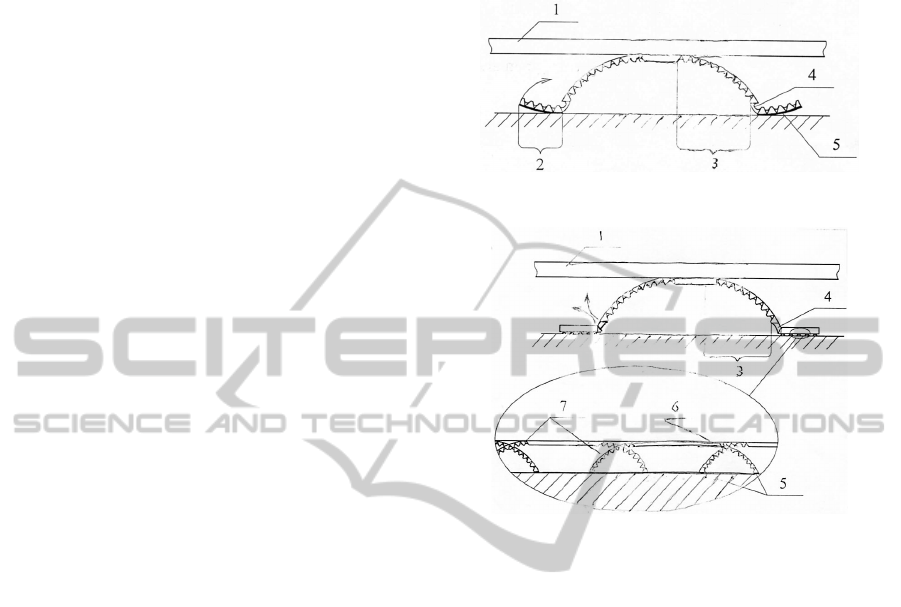
Version one of the design of the mobile minirobot
leg (Fig. 4) involves platform (1) and
thermomechanical actuators with main (3) and
additional (2) zones of deformation. The angle
between two actuators is 180 ; the main (3) and
additional (2) zones are connected with a polyimid
flexible insertion (4). The additional zone (2) forms
a pad and is intended for pressing the leg down to
the surface and detaching it from the surface. The
adhesion layer (5) on the leg enables the robot to
move along complex surfaces under various
conditions, including a state of weightlessness.
Main zone (3) of deformation permits the
microrobot to move at least along two planes, in two
directions along each of these planes, depending on
the operating mode.
Figure 4: Design of a microrobot leg (version one).
Figure 5: Design of a microrobot leg (version two).
Design version two (Fig. 5) differs from version
one in the presence of additional zone (2) that is
implemented by a silicon beam with
thermomechanical actuators of smaller size. The
additional deformation zone serves for the motion of
the robot along planar surfaces, while the main zone
is used for overcoming uneven stepped segments of
the surface.
The experimental prototype of the robotic
platform is shown in Fig. 6. This prototype is
characterized by the following parameters: voltage
up to 20 V, temperature up to 200C, deviation angle
of the actuator up to 60 degrees, the velocity of the
platform up to 10mm/min.
The phases of motion for version one of the
microrobot design are shown in Fig. 7. Introduce the
following notation: t
lh
is the unbending time for the
actuator under heating, t
lc
the bending time for the
actuator under cooling, t
fh
the unbending time for
the pad actuators under heating, t
fc
the bending time
for the pad actuators under cooling (we assume that
t
fh
<t
fc
and t
lh
<t
lc
); N
th
the power supply needed for
unbending the leg actuator, N
fh
the power supply
needed for unbending the pad actuator, N
fs
the
power supply needed for keeping the leg in the
unbent state, N
fs
the power supply needed for
DesignofMobileMicrorobotswithThermomechanicalActuators
255
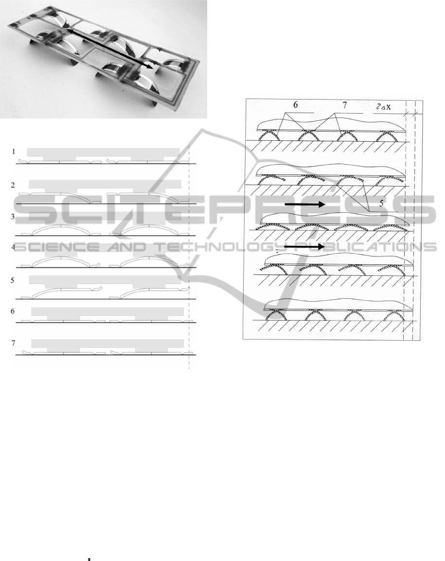
Figure 6: Experimental prototype of the robotic platform.
Figure 7: Motion phases of mobile microrobot.
keeping the pad in the bent state.
Calculate the minimal time required for each
phase of motion and the corresponding energy
consumption. Let the legs and the pads be bent in the
initial position. Below, we characterize each (ith)
phase and give the expressions for the duration t
i
of
this phase and the respective energy consumption A
i
1. Unbending four legs and two front pads:
t
1
=t
lh
, A
1
=4N
lh
t
l
+2N
fh
t
fh
2. Bending two front legs and unbending two
rear pads; two rear legs and two front pads being
kept unbent:
t
2
=t
lc
, A
2
= 2N
fh
t
fh
+2N
ls
t
lc
+2N
fs
t
lc
+2N
fs
(t
lc
-t
fh
)
3. Bending two rear legs, all pads being kept
unbent: t
3
=t
lc
; A
3
=4N
fs
t
lc
4. Bending two front pads, the rear pads being
kept unbent:
t
4
=t
fc
, A
4
=2N
fs
t
fh
5. Unbending two front legs, the rear legs being
kept bent:
t
5
=t
lh
, A
5
=2N
lh
t
lh
+ 2N
fs
t
lh
6. Unbending two rear legs, all pads and the front
legs being kept unbent:
t
6
=t
lh
, A
6
=2N
lh
t
lh
+4N
fs
t
lh
+2N
ls
t
lh
7. Bending two rear pads, two front pads and all
legs being kept unbent: t
7
=t
fc
, A
7
=2N
fs
t
fc
+4N
ls
t
fc
Figure 8: Mode of motion of the mobile microrobot along
a flat surface.
Phases 2-7 are then repeated. Phase 1 starts the
motion of the robot from the initial state. Time t
1
and
energy A
1
are needed for this phase.
Time t
=t
1
+t
2
+t
3
+t
4
+t
5
+t
6
+t
7
and energy
A
=A
2
+A
3
+A
4
+A
5
+A
6
+A
7
are needed for one cycle
of the motion along a straight line:
2224
82 64 4
fh fh ls lc lh fc
f
clc fh lh fc lhlh
A
Nt N t t t
Nt t t t Nt
(3)
The experiments with a prototype of the actuator
demonstrate the following time and power
characteristics: t
lh
=4s, t
lc
=9s, t
fh
=2s, t
fc
=5s,
N
lh
=1,36W, N
ls
=0,45W, N
fh
=0,68 W, N
fs
=0,23 W
Then the energy and time needed for one cycle
of motion along a straight line on a horizontal plane
are given by
70.94 J, 36 sAt
.
The phases of motion of an inspector microrobot
(version two) along flat and stepped surfaces are
shown in Fig. 8 and Fig. 9, respectively.
ICINCO2015-12thInternationalConferenceonInformaticsinControl,AutomationandRobotics
256
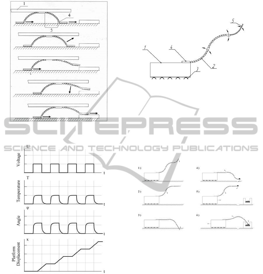
Figure 9: Mode of motion of the mobile microrobot along
a stepped surface.
Figure 10: Motion cyclogram of the microrobot leg.
The microrobot leg motion cyclograms (Fig. 10)
plots the time histories of the control voltage,
temperature of the actuator, the angle of deflection
of the leg, and the displacement of the robot. The
control voltage heats the actuator plate, which
causes its deflection by an angle of up to 90°.
The general view sketch of the inspector
microrobot is depicted in Fig. 11. The microrobot
has a micromanipulator based on thermomechanical
actuators. This robot can be used for space
exploration purposes. For example, it can grasp
ground samples of planets and put them into a
container (Fig. 12).
Figure 11: The general view sketch for an inspector
microrobot.
5 CONCLUSIONS
Major problems related to designing microrobots on
the basis of new type of thermomechanical actuators
are discussed. Mechanical structures of the robots,
Figure 12: Inspector microrobot taking ground samples.
acting forces, phases and conditions of motion are
considered and analyzed. A concept of an inspector
microrobot for planet missions is proposed. A
mathematical model of the motion of the robot is
developed to study and simulate the behaviour of
robot subject to various external conditions.
Parametric analysis will of the model and
experimental studies of the prototype of such a robot
are planned.
ACKNOWLEDGEMENTS
This study was supported by the Russian Science
Foundation (Grant #14-19-00949).
DesignofMobileMicrorobotswithThermomechanicalActuators
257

REFERENCES
Erdem E. Y., Chen Y. M., Mohebbi M., Darling R. B.,
Böhringer K. F., Suh J. W., Kovacs G. T., 2010 A
Thermally Actuated Omnidirectional Walking
Microrobot. Journal of Microelectromechanical
Systems; 19 (3), p.433-442.
Ebefors T., Mattson J. U., Kälvesten E., Stemme G., 1999
A walking silicon miro-robot // The 10th Int.
Conference on Solid-State Sensors and Actuators
(Transducers’99) – Sendai, Japan., p. 1202-1205.
Patent of USA US2012/0168233. Robotic devices and
methods / J.V. Clark (US); Purdue research foundation
(US) – Publ. 05.07.2012 – 8p.
Patent of USA US2010/0145511. Microcrawler and
conveyor robots, controllers, systems, and methods /
D.O. Popa (US), R. Murthy (US), A.N. Das (US);
Fulbright&Jaworski L.L.P. (US). Publ. 10.06.2010,
p.17.
The MEMS Handbook, 2002 Edited by Mohamed God-el-
Hak. Mechanical engineering handbook series, CRC
Press, USA, p. 26-63, 26-27.
Harc J. Madou. , 2002 Fundamentals of Microfabrication.
The Science of Miniaturization. Second Edition. CRC
Press, USA, 723 pp.
Patent of Russia RU2518258. Microsystem device for
temperature control of surface of spacecraft / A.A.
Zhukov (RU), I. P. Smirnov (RU), A. S. Selivanov
(RU), D. V. Kozlov (RU), I. V. Churilo (RU). Publ.
10.06.2014, Bull. № 16, 16 p.
Wallace B. P., Hampton P. J., Bradley C. H., Conan R.,
2006 Evaluation of a MEMS Deformable Mirror for
an Adaptive Optics Test Bench // Opt. Express.. №
14(22). P. 10132-10138.
Patent of Russia RU2456720. Microsystem apparatus
controlling surface for mounting small antenna /A. A.
Zhukov (RU), I. P. Smirnov (RU), A. S. Korpukhin
(RU), D.V. Kozlov (RU). Publ. 20.07.2012, Bull. №
20, 15 p.
Norton A., Evans J., Gave D. et al., 2009 Preliminary
Characterization of Boston Micromachines’ 4096-
actuator Deformable Mirror // MEMS Adaptive Optics
III. Proc. SPIE. V. 7209. P. 720901-720901-7.
Ebefors T., Mattson J. U., Kalvesten E., Stemme G. , 1999
A Walking Silicon Micro-robot // The 10th Int. Conf.
on Solid-State Sensors and Actuators (Transducers’
99). Sendai, Japan. P. 1202-1205.
Ebefors T., 2000 Polyimide V-groove Joints for Three-
dimensional Silicon Transducers // Thesis for the
Degree of Doctor of Philosophy at the Royal Institute
of Technology. Stockholm, Sweden. 143 p.
Patent of Russia RU2448896. Thermal micromechanical
actuator and method of making said actuator / A. A.
Zhukov (RU), I. P. Smirnov (RU), A. S. Korpukhin
(RU), D.V. Kozlov (RU), P.G. Babaevsky (RU). Publ.
27.04.2012, Bull. № 12, 20 p.
Bolotnik N. N., Gradetsky V. G., Kozlov D. V., Smirnov
I. P., Chashchukhin V. G., 2015 Physical
characteristics of the sensing elements of feedback
sensors combined with thermomechanical actuators
for plant micromotion control systems. Journal of
Computer and Systems Science International, Vol. 54,
No 1, pp. 140-150.
Gradetsky V. G., Knyazkov M. M., Fomin L. F.,
Chashchukhin V.G., 2010 Miniature robot mechanics.
Nauka, Moscow (in Russian).
Kozlov D. V., Smirnov I. P., Korpukhin A. S., Zhukov A.
A., Babaevsky P. G., Suchorukov A. G. , 2010
Estimation of influence of multicycle bending on
thermal deformation characteristics of elastic-hinged
beams of thermal microactuators. Nano- and
Microsystem Technology, No 12, p. 22-25.
Korpukhin A. S., Babaevsky P. G., Zhukov A. A., Kozlov
D.V., Smirnov I.P., 2011 Influence of forming
conditions and layer width on thermodeformation
characteristics of polyimide-silicon elastic-hinged
beams of thermal actuators. Nano- and Microsystem
Technology, No 2. pp. 34-40.
Xu T. B., Cheng Z. Y., Zhang O. M., 2002 High-
perfomance micromachined unimorph actuators based
on electrostrictive poly(vinylidenc fluoride-
trifluoroethylenc) copolymer. Applied physics letters,
v. 80, #6, pp. 1082-1084.
Yang W. M., Chou S. K., Shu C., Li Z. W., Xue H., 2002
Development of microthermophotovoltaic system.
Applied physics letters, v.81, #27, pp. 5255-5257.
Fahrner W. R., Job R., Werner M., 2001 Sensors and
smart electronic in harch environment applications.
Microsystem Technologies 7(2001), Springer-Verlag,
pp. 138-144.
Kondon Y., Yokota S., 1997 Micro in-pipe mobile
machines by making use an electro-rheological fluid.
Proc. IROS-97, pp. 1672-1677.
ICINCO2015-12thInternationalConferenceonInformaticsinControl,AutomationandRobotics
258
