
A Complete Sensor-based System to Navigate Through a Cluttered
Environment
A. Durand-Petiteville
1
, V. Cadenat
2,3
and N. Ouadah
4
1
University of California, Davis, Department of Biological and Agricultural Engineering,
One Shields Avenue, Davis, CA 95616-5270, U.S.A.
2
CNRS, LAAS, 7 avenue du colonel Roche, F-31400 Toulouse, France
3
Univ. de Toulouse, UPS, LAAS, F-31400, Toulouse, France
4
Centre de D
´
eveloppement des Technologies Avanc
´
ees,
Cit
´
e du 20 Ao
ˆ
ut 1956, BP 17 Baba Hassen, 16303 Algiers, Algeria
Keywords:
Sensor-based Navigation, Mobile Robot, Topological Map.
Abstract:
This article deals with the autonomous navigation problem of a mobile robot in a cluttered environment. We
propose to have a different perspective than the traditional way of splitting the problem into two categories:
the map-based ones and the mapless ones. Here we divide navigation systems into six processes: perception,
modeling, localization, planning, action and decision. Then we present how those processes are organized
into an architecture to perform a navigation. It is shown that this framework embraces any navigation system
proposed in the literature and how it allows to create new combination of processes. We then detail our solution
to the problem which mainly consists in coupling sensor-based controllers with a topological map. Moreover
we present the used tools that we have developed over the last years as well as the ones from the literature.
Finally we present experimentation results of a long-range navigation based on the proposed approach where
a robot drives through an environement despite of occlusions and possible collisions due to obstacles.
1 INTRODUCTION
In this paper, we consider the autonomous navigation
problem of a mobile robot in a cluttered environment.
It consists in reaching a goal through a given envi-
ronment while dealing with unexpected events mainly
due to obstacles (Choset et al., 2005). To do so, differ-
ent sensors have been used and a wide variety of tech-
niques have been proposed in the literature. Among
them, the strategies based on vision have significantly
drawn the interest of researchers (Bonin-Font et al.,
2008). Here, we focus on particular visual naviga-
tion approaches consisting in coupling sensor-based
controllers to a topological map. Indeed they seem to
be appropriate to our problem for two reasons. First
they allow to deal with unexpected events thanks to
the reactive behavior of the sensor-based controllers.
Second, it is possible to navigate safely over large dis-
tances using the map. The literature provides several
approaches relying on a similar reasoning. Among
them, we focus on the works based on the concept of
visual route (Matsumoto et al., 1996). This latter is
a topological map built by organizing images taken
during a pre-navigation step (Royer et al., 2007). It
is then coupled with a controller allowing to make
the robot move along this road. See for example the
works by (Booij et al., 2007) (Courbon et al., 2009)
for omni-directional vision systems and by (Krajn
´
ık
and P
ˇ
reu
ˇ
cil, 2008) (Courbon et al., 2009) for pinhole
cameras. Note that in these works vision is used to
build the topological map and to reconstruct the robot
state value. This choice prevents from keeping the
well known advantages of image-based visual servo-
ing in terms of robustness and precision (Chaumette
and Hutchinson, 2006). Moreover, none of these ap-
proaches takes into account the two major problems
of visual navigation: occlusions, i.e. the landmarks
loss, and collisions with obstacles. A set of works
(Cherubini et al., 2011) (Cherubini and Chaumette,
2013) have recently developed a visual navigation
strategy allowing to avoid unexpected obstacles while
tolerating partial occlusions.
We believe that these weaknesses come from the
fact that the traditional framework proposed in the lit-
erature does not provide sufficient guidelines to build
a navigation system. In this framework (Choset et al.,
166
Durand-Petiteville A., Cadenat V. and Ouadah N..
A Complete Sensor-based System to Navigate Through a Cluttered Environment.
DOI: 10.5220/0005502201660173
In Proceedings of the 12th International Conference on Informatics in Control, Automation and Robotics (ICINCO-2015), pages 166-173
ISBN: 978-989-758-123-6
Copyright
c
2015 SCITEPRESS (Science and Technology Publications, Lda.)

2005) (Bonin-Font et al., 2008), the strategies are
classically split into two categories: the map-based
ones and the mapless (or reactive) ones. The first
ones allow to realize large displacements while suf-
fering from a lack of flexibility when dealing with
unmapped obstacles and some sensitivity in the pres-
ence of errors. The second ones allow to handle the
unexpected events much more efficiently than the pre-
vious ones but they are not adapted to perform long
displacements. Thus, the traditional formalism does
not cover the visual navigation strategies we are inter-
ested in, as they cumulate the advantages of both local
and global approaches. Furthermore, as previously
mentioned, it does not provide sufficient guidelines to
help the strategy design. This is due to the fact that
the framework categorizes navigation methods using
only one criterion: the presence or not of a priori data
about the environment, which is limited. For us, it ap-
pears to be worthwhile to analyze the problem using
a different perspective. To do so, we propose to de-
scribe the navigation strategy using the six processes
which are involved in it, namely: perception, model-
ing, planning, localization, action and decision. These
processes are in turn organized into an architecture
which indicates which ones are used and how they in-
teract together. Thus, to design a navigation system,
it is necessary to select a method allowing to instan-
tiate each process. The system is then defined using
the methods involved in each process.
Based on that navigation framework, we have
worked over the last decade in order to create a com-
plete navigation system allowing to visually navigate
through a cluttered environment using sensor-based
controllers. Indeed, we believe that those controllers,
thanks to their nice reactive behavior, allow to effi-
ciently guide a robot towards a goal while dealing
with obstacles. To design such a system, we have
developed methods to avoid obstacles based on laser
range-finder data (Sou
`
eres et al., 1998), to switch
from one controller to another one depending on the
needs (Sou
`
eres and Cadenat, 2003), to reconstruct
visual features in order to manage occlusions (Du-
rand Petiteville et al., 2013). In this paper we de-
tail the instantiation of each process and describe how
they are organized in the chosen architecture. Fi-
nally, thanks to experimentations, we show that the
proposed navigation system allows to deal efficiently
with unexpected events such as visual signal losses or
obstacles, contrary to most other similar techniques.
This paper is organized as follows. The next sec-
tion is devoted to the navigation framework. Then,
we present our approach in part 3, highlighting the
choices we have made for the processes. We end by
showing results validating the proposed approach.
2 THE NAVIGATION
FRAMEWORK
Six processes are generally involved in a given navi-
gation system: perception, modeling, planning, local-
ization, action and decision. The level of autonomy
and the performances of the system can be evaluated
only after having considered each of those processes.
This is the reason why we believe that it is worthwhile
to analyze a navigation through these processes. In
this section we exhibit different architectures describ-
ing the processes and their collaboration. We consider
several scenarii and for each of them we describe the
corresponding architecture. It will be shown that any
navigation approach can match the proposed frame-
work, demonstrating its generality. We propose to or-
ganize our presentation around the choice of the con-
troller allowing to drive the robot towards the goal.
2.1 ”State feedback” based Controller
We consider a robot driven to its goal thanks to a state
feedback controller as its action process. To compute
the control inputs, the state value in the world frame
has to be known at any time, which means that the
localization process has to be instantiated with a met-
ric localization. The robot capacity to geometrically
localize itself is then a necessary condition to success-
fully perform the navigation. Let us note that the dis-
tance that the robot can cover is significantly limited
by the localization precision. Indeed, a too large error
on the state value will result in inconsistent control
inputs.
We now deal with the collisions problem due to
obstacles presence in the environment. In this case
there are two solutions, either based on the action or
the planning processes. The action one consists in
controlling the robot using two controllers: a first one
making the error between the current and the desired
poses vanish, allowing to reach the goal, and a sec-
ond one performing the obstacle avoidance using ex-
teroceptive data. It is then necessary to instantiate the
decision process with a supervision module able to
select the adequate controller. This solution, which
guarantees the non-collision with obstacles, does not
allow to ensure the navigation success. Indeed, the
obstacle avoidance is locally performed and does not
take into account the goal. Some local minima might
arise. The second solution consists in following a pre-
viously planned collision free path. To achieve this
aim, we have to use the modeling process. If the
model represents the whole scene, then the navigation
simply consists in following the planned itinerary us-
ing a state feedback controller. The decision process
ACompleteSensor-basedSystemtoNavigateThroughaClutteredEnvironment
167

is no more required. If the environment is not com-
pletely modeled, it may be necessary to update the
map when an obstacle appears on the robot path. Af-
ter the update, a re-planning step is performed. In this
case, the decision process which decides when updat-
ing and re-planning is mandatory. Finally, it should
be noticed that the metric localization is required and
limits the navigation range for each solution.
2.2 ”Output feedback” based
Controller
We now consider a robot moving towards its goal us-
ing an output feedback controller as its action process.
The initial pose is unknown whereas the desired one
is defined by measures with respect to a landmark.
The robot can converge toward the desired pose if the
landmark can be perceived at any instant. It is now
the sensor range which limits the navigation range. In
this case no localization process is required.
We now focus on the collisions problem. A first
solution consists in using a sole output feedback con-
troller to reach the desired pose while avoiding ob-
stacles. A second idea is to add another controller in
the action process. It has to guarantee the non colli-
sion with obstacle. A decision process selecting the
adequate controller is then required. For both solu-
tions, local minima problems may occur. Moreover,
the navigation range is still limited by the sensors
range. A modeling process containing global infor-
mations must then be used to perform a long range
navigation. The global information can be added us-
ing a metric map or a topological map. In the first
case, the planning process can plan a path taking into
account the features availability at each pose. The
planned itinerary is then composed by several land-
marks successively used to compute the control in-
puts. Moreover, for a static environment, joint limits,
visibility and obstacles can also be considered in the
planning step. Nevertheless, this approach requires
environment, robot and sensors reliable models. In
the second case, a topological map is used to provide
the necessary global information. Here, the additional
data associated to the graph nodes usually correspond
to the desired features or landmarks. As previously,
the planned itinerary is made of measures or land-
marks set to reach. This approach is based on a partial
environment representation. The model is then less
sensitive to the environment modifications, but does
not allow to take into account several constraints such
as obstacles or joints limits during the planning step.
A topological localization is needed.
As we have seen, a navigation system does not
solely depend on the presence or not of a map to de-
scribe the environment, and trying to establish a clas-
sification using this sole criterion appears to be lim-
ited. On the contrary, considering the six processes
and organizing them into an architecture allows to de-
scribe any navigation system and much more provides
useful guidelines to build an efficient solution. In-
deed, it becomes possible to create any combination
of processes and instantiations in order to obtain ro-
bust navigation systems. Following this idea, we now
present our own solution to the navigation problem.
3 OUR SENSOR-BASED
NAVIGATION STRATEGY
In this section, we present our sensor-based solution
to make a robot navigate through a cluttered environ-
ment. We first introduce the considered robotic sys-
tem, then the architecture, and finally we detail how
each process has been instantiated.
3.1 The Robotic System
In this paper we consider an iRobot B21R mo-
bile platform, which is a differential robot (see fig-
ure 1(a)). Its standard equipment has been extended
with a vision system composed of a digital Point Grey
CCD camera, mounted on a Directed Perception Pan
Tilt Unit (PTU). Only the pan degree of freedom will
be used in our experiments. The camera is able to pro-
vide 640x480 RGB images. A short range SICK laser
range finder has been fixed at the bottom of the mobile
base. It is able to detect obstacles up to 10 meters with
a 180 degrees field of view and its resolution is about
1.9 points per degree. Sensors acquisitions and ac-
tuators management are performed thanks to an open
source tool developed in LAAS which uses a C/C++
interfacing scheme.
3.2 The Navigation Architecture
Our architecture is based on the previous analysis and
uses the introduced framework. To instantiate the per-
ception, action and modeling processes, we have cho-
sen to use a camera and a laser range finder, sensor-
based-controllers and a topological map. Several rea-
sons motivate this choice. Firstly, as explained in
the introduction, vision has been widely exploited for
performing various tasks (manipulation, navigation,
etc.) and for different kinds of robots (humanoids,
autonomous ground vehicles, etc.) (Bonin-Font et al.,
2008). It is then worthwhile to consider this sensor
to guide our robot during the navigation. Further-
more we have decided to couple it with a laser range-
ICINCO2015-12thInternationalConferenceonInformaticsinControl,AutomationandRobotics
168
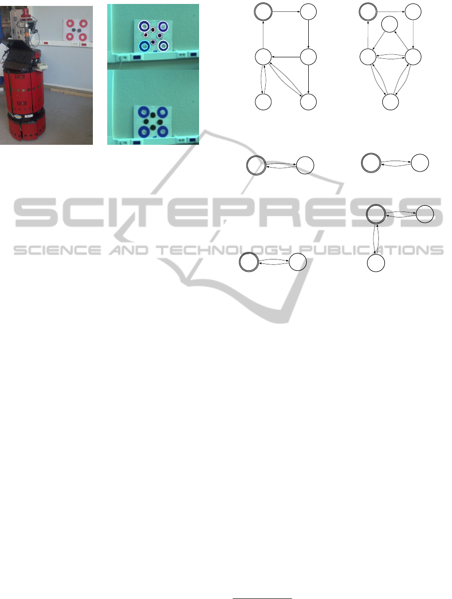
(a) The robot and the target. (b) The detection of the circles of
interest and of the pattern.
Figure 1: The experimental set-up and the environment.
finder because such a device allows to efficiently de-
tect obstacles and to provide accurate data to avoid
them. Secondly, we have chosen to instantiate the ac-
tion process using sensor-based controllers. Indeed,
they are suitable to deal with unexpected events such
as unmapped obstacles due to their reactivity aspect.
Moreover, they do not require any metric localization,
which allows to reduce the navigation failure risk due
to a localization error. Finally, the environment has
been represented by a topological map because this
model presents several advantages with respect to its
metric alter-ego, namely: (i) the metric localization is
no more required, (ii) it provides sufficient data to per-
form a navigation task, without significantly increas-
ing the problem complexity and (iii) it is less sensitive
to scene modifications. Now we focus on the localiza-
tion and planning processes. To instantiate them, we
have selected methods matching the previous choices
done for them. As we plan to use a topological map,
we have chosen to instantiate the planning process by
an algorithm from graph theory, and the localization
process by a topological localization method. Finally,
the decision process will be performed by supervi-
sion graphs which will define how each process runs
with respect to the global strategy. Thanks to the new
framework, our navigation architecture owns the ad-
vantages of both map-based and reactive strategies.
3.3 The Navigation Processes
3.3.1 Perception
The robot navigates using artificial landmarks which
are fixed in the environment in such a way that a topo-
logical map can be built. These landmarks are made
of a set of colored circles together with a particular
pattern in the center (figure 1(a)). The red and white
B3 B2
B5
B0 B1
End_rot
End_planning
Depth_conv
End_vs
&
!Land_found
!Obs
Obs
B4
Depth_conv
&
Obs
End_re
Land_found
(a) The mobile base supervision
process
C0 C1
End_planning
C3 C2
Depth_conv
End_look
Depth_conv
C4
!Obs
Obs
!Land_found
&
End_vs
Depth_conv
End_look
&
Obs
Land_found
End_re
C5
(b) The camera supervision process
S0 S1
Occ
!Occ
(c) The perception super-
vision process
L0
L1
End_rot ||
End_look ||
Land_found
Depth_conv
(d) The localization su-
pervision process
M0
M1
End_rot
&
!Land_found
End_mod
(e) The modeling supervi-
sion process
P0
P1
Land_found
P2
End_mod
||
End_rot
End_planning
End_updating
(f) The planning supervision
process
Figure 2: The supervision graphs (! : not – k : or – & : and).
B0 : Rotation B1 : Nothing
B2 : Initialization B3 : Visual servoing
B4 : Obstacle avoidance B5 : Re-orientation
C0 : Nothing C1 : Initialization
C2 : Looking for the next target C3 : Visual servoing
C4 : Obstacle avoidance C5 : Reorientation
S0 : Measured visual features S1 : Estimated visual features
& laser rangefinder & laser rangefinder
L0 : Identify current landmark L1 : Nothing
M0 : Nothing M1 : Suppress a connection
P0 : Nothing P1 : Update the current landmark
P2 : Plane a path
circles are used to feed the control laws, while the
pattern, made of several black circles in the middle of
the target, allows to identify the target and localize the
robot in the topological graph. The first objective of
the image processing is to extract the center of the red
and black circles. It relies on two criteria respectively
based on color and on shape. The proposed image
processing technique allows to detect 60x60 cm tar-
gets (Figure 1(b))
1
up to 10 meters.
1
The red circles diameter is 30 cm and the distance be-
tween two circles is about 40 cm.
ACompleteSensor-basedSystemtoNavigateThroughaClutteredEnvironment
169

The robot is also equipped with a laser range
finder allowing to detect the obstacles around the mo-
bile base by providing a local scan of the environ-
ment. These data are then used to evaluate if an ob-
stacle is close enough to be considered as dangerous.
In such a case, they are also required to compute the
control law allowing to avoid the considered obstacle.
During the navigation, several phenomenons can
lead to the lack of visual features: camera temporary
breakdown, image processing errors, or even occlu-
sions of the landmarks by an obstacle. To success
the mission, a method managing the loss of the vi-
sual signal is required. We have developed an algo-
rithm (Durand Petiteville et al., 2013) which allows
to reconstruct the point visual features and their depth
in the general case of a 6 degrees of freedom cali-
brated camera. While visual data are available, the
algorithm uses a number n of images to estimate the
current depth of each visual features. If the visual sig-
nal is lost, the last estimated depth is used as an initial
value to predict the current one. It is then possible to
estimate the current visual features. They are used to
feed the control law allowing to perform the task. It
then becomes possible to manage a total visual signal
loss during the navigation.
3.3.2 Modeling
We now focus on the modeling process implementa-
tion. As previously mentioned, it is instantiated by a
topological map, which consists of a directed graph.
To build it, we have first chosen to associate to each
node a landmark present in the scene. Thus, if there
are n
l
landmarks, then the graph is composed of n
l
nodes. To connect the nodes, we detect if there ex-
ists a common visibility area, i.e. if two landmarks
can be seen simultaneously from a given robot posi-
tion. To achieve this aim, we associate to the node
N
i
, with i ∈ [1, ..., n
l
], several robot poses denoted by
S
∗
i− j
, with j ∈ [1, ..., n
l
] and i 6= j. S
∗
i− j
corresponds to
the pose associated to the landmark T
i
that the robot
should reach if it has then to navigate with respect to
the landmark T
j
. If S
∗
i− j
is identical for all T
j
, then
it is denoted by S
∗
i
. An arc A(N
i
, N
j
) is then created
if the landmark T
j
, associated to the node N
j
, can be
seen from the pose S
∗
i− j
, associated to the node N
i
,
with i 6= j. Finally, we also associate to the node N
i
sensory data D
i
allowing to identify landmark T
i
. D
i
is defined by the number of black circles in the middle
of the target.
3.3.3 Localization
During the navigation the robot has to localize itself
in the graph. We then need to use a topological local-
ization method. The process consists in matching the
data perceived by the sensors with the ones contained
in the topological map (Segvic et al., 2009). Here,
the process has to identify the landmarks in the field
of view of the camera. They are made of black cir-
cles dedicated to localization. Those latter are identi-
fied thanks to image processing and the obtained re-
sult is matched to the database. Thus the robot knows
which landmark is lying in the camera field of view
and therefore where it is in the graph.
3.3.4 Planning
The planning process has to provide a path allowing
to reach the goal from the initial robot configuration.
To do so, the first step consists in finding the initial
and final nodes. The first one is obtained during the
initial localization step during which the robot makes
a whole turn on itself to scan the environment. Each
landmark that is seen is considered as a possible initial
node. The final node, the goal to be reached, is given
by the user. Then, for each initial node, we compute
the shortest path using the Dijkstra algorithm. Fi-
nally, we keep the shortest path. The obtained path
T
P
is therefore made of a sequence of n
P
landmarks
[T
P1
, ..., T
Pn
P
] to be reached successively.
3.3.5 Action
We have designed five output feedback controllers to
successfully realize the mission. We have used the
task function approach (Samson et al., 1991), where
each considered task is modeled by a particular func-
tion, the so-called task function. This latter must be
chosen so that it is zero when the mission is success-
fully performed. It then suffices to design a controller
making the corresponding task function vanish. We
propose to impose an exponential decrease to the task
function as it is done in (Cadenat et al., 2012).
The first controller allows the robot to reach a
pose with respect to a given landmark. This latter
is described by a set of point-wise visual features
which can be by the vision system. We have cho-
sen to design an Image Based Visual Servoing (IBVS)
(Chaumette and Hutchinson, 2006). This controller
allows to make the current visual features converge
towards a preselected reference value which corre-
sponds to the one obtained at the desired pose.
The second controller is intended to guarantee non
collision by allowing the vehicle to follow a security
envelope around an obstacle. To achieve this aim, we
have used the path following controller introduced in
(Cadenat et al., 2012). It should be noticed that this
controller allows to drive the mobile base only. In-
deed, during the avoidance phase, the pan-platform is
ICINCO2015-12thInternationalConferenceonInformaticsinControl,AutomationandRobotics
170

driven separately to keep the landmark of interest in
the camera field of view. This is the reason why we
have decoupled the motions of the mobile base and
the pan-platform during this phase. We have used the
controller proposed in (Durand Petiteville et al., 2011)
which allows to maintain the target in the center of the
image while compensating the mobile base motion.
The fourth controller is the reorientation one
which intends to answer some problems due to the
use of IBVS (Durand Petiteville et al., 2011). They
may occur when switching from the current landmark
to the next one. We have defined a controller allowing
to suitably orientate the mobile base toward the next
target when it has been detected (Durand Petiteville
et al., 2011). When the camera is orientated towards
the next landmark, this controller progressively align
the directions of the mobile base and of the camera. It
has to be coupled with the pan-platform controller.
FinallyS the robot has to be able to find the next
landmark. To do so, the pan-platform is provided a
nonzero angular velocity which allows to make it turn
until the target is found or until the searching rotation
has been completed. During this phase, the mobile
base is driven either with an IBVS fed with estimated
visual features in the free space or with the path fol-
lowing controller in an obstacle neighborhood.
Now, five separate controllers are available. The
global control law will be defined by switching be-
tween these controllers depending on the context (see
the decision process). To guarantee the global control
law continuity at the switching time, we have used an
approach, called dynamical sequencing, which allows
to insure that the robot velocities provided by both
controllers are equal at the switching time (Sou
`
eres
and Cadenat, 2003) (Cadenat et al., 2012).
3.3.6 Decision
The decision process defines the navigation strategy
which relies on the activation/deactivation of the pre-
viously mentioned tools. We have designed a super-
vision graph for each process. First we focus on the
action supervision graphs (see figures 2(a) and 2(b)).
• At the beginning, to compute the path, the robot
identifies the landmarks which can be seen from
its initial position by performing a 360
◦
rotation
(B0 and C0).
• When it is over (End rot = 1), it waits for the path
T
P
= [T
P1
, ..., T
Pn
p
] to be computed (B1 and C0).
• When it is available (End planning = 1), the ini-
tialization step is realized (B2 and C1) by per-
forming small rotations to estimate the visual fea-
tures depths of T
P1
. It ends when the estimation
has converged (Depth conv = 1).
• Now, the first sub-navigation can be launched.
The mobile base is controlled using either the
IBVS (B3) or the obstacle avoidance (B4) depend-
ing on the risk of collision evaluated from laser
data (Obs = 1).
• During the sub-navigation, the camera regularly
looks for T
P2
(C2) by scanning the environment.
If this latter is detected, a subnavigation with re-
spect to T
P2
is executed. If this latter is not found
(End found = 1), the camera remains controlled
using either the IBVS (C3) or the obstacle avoid-
ance (C4) controllers. Moreover, the depth esti-
mation process is relaunched. When it converges,
the robot looks for T
P2
one more time. This loop
is repeated until: T
P2
is found (Land found = 1)
or the sub-navigation is over (End vs = 1). In this
last case, the robot performs a whole turn on itself
to try a last time to identify the next target (B0
and C0). If it is not found, the map is updated and
a new path is computed. If no path can be com-
puted, we consider that the navigation has failed.
• If T
P2
has been found (Land found = 1), the re-
orientation step is launched (B5 and C5). The
latter is stopped when the robot is oriented to-
wards the landmark T
P2
(End re = 1). Then a sub-
navigation is launched. This loop is repeated until
the robot reaches the final landmark or the navi-
gation fails.
During the navigation, perception modalities may
change. Indeed, due to occluding obstacles, the cur-
rent landmark might not be perceived. Thus the robot
uses either the measured visual features or the esti-
mated ones when an occlusion occurs (Occ = 1) (fig-
ure 2(c)).
The robot has to localize itself when: (i) the mis-
sion begins; and (ii) the camera is looking for the
next target (figure 2(d)). In case (i), it has to iden-
tify the landmarks which lie in the field of view
(Depth conv = 1). The result is used to define the ini-
tial nodes of the path. This step is over when the ro-
tation is finished (End rot = 1). In case (ii), the robot
has to determine whether the target in its field of view
is the next target or not. It ends when the next land-
mark is found (Land found = 1) or when the ”looking
for” step is over (End look = 1).
Finally, we consider the modeling (figure 2(e))
and planning (2(f)) processes. At the end of a sub-
navigation, two cases may occur. Either the next tar-
get has been found (Land found = 1) or not. In the
first case, the current target is updated (P1), by con-
sidering the next target as the current one. In the sec-
ond case, a rotation is launched to try to find it again
in the robot vicinity. If it fails (Land found = 0 &
End rot = 1 ), then the map is updated by suppress-
ACompleteSensor-basedSystemtoNavigateThroughaClutteredEnvironment
171
ing the corresponding connection. Then a new path is
planned (P2). If no path can be calculated, we con-
sider the navigation has failed. Otherwise, the new
path is performed to reach the desired robot pose.
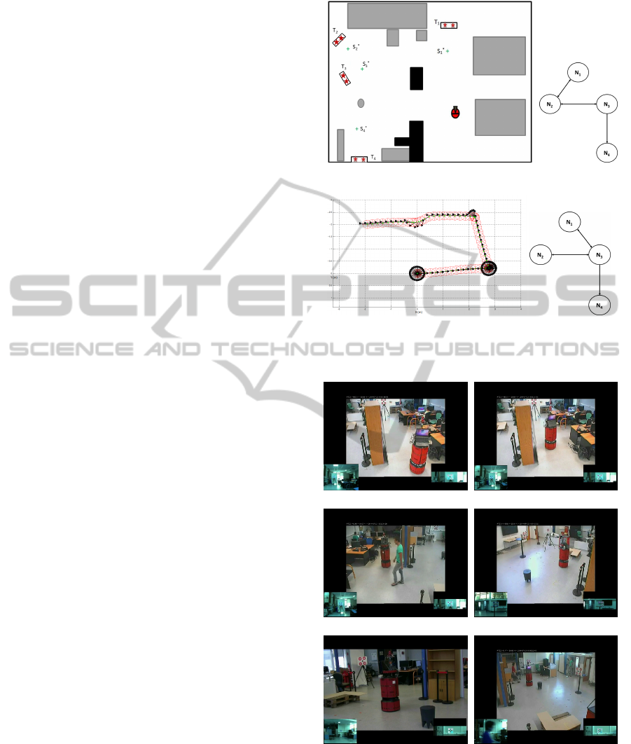
4 EXPERIMENTS
4.1 The Experimental Conditions, the
Environment and Its Modeling
The long range navigation experiments were car-
ried out in an indoor environment cluttered by oc-
cluding (black) and non occluding (gray) obstacles
(figure 3(a)). There are n
l
= 4 artificial targets
{T
1
, T
2
, T
3
, T
4
}. Prior to the navigation, we have cho-
sen the reference poses S
∗
i
(figure 3(a)) and follow-
ing the reasoning described in part 3.3.2, we have ob-
tained a topological map (figure 3(d)). However, we
want to force the robot to update the map and replan
the path. To do so, we have deliberately introduced an
error in this map by suppressing the link between N
1
and N
3
. The robot will then be given the graph repre-
sented in picture 3(b) instead of the one displayed in
figure 3(d). In addition, we have also replaced land-
mark T
2
by a target without any pattern. The robot
will not then be able to recognize this landmark if it
is required for the mission. Finally, the camera has
been calibrated considering the lens distortions for an
accurate control law computation.
4.2 Live Experiments, Results and
Discussion
The goal is to reach landmark T
4
, starting from a given
initial position. A snapshot of the experimental test is
shown in figure 4. A video can be found at the follow-
ing url: http://youtu.be/OWbEPL4x-Pk. As landmark
T
4
cannot be seen from the initial pose (figure 4(a)), a
localization step is launched and the robot turns on it-
self to identify the landmarks lying in its vicinity. Af-
ter this motion, T
1
is recognized and a path connecting
T
1
and T
4
is computed: {T
1
, T
2
, T
3
, T
4
} 3(b). Then, the
mission starts. An IBVS controller is selected to con-
verge towards T
1
(figure 4(b)). During this motion a
pedestrian crosses the robot path, occluding the cam-
era view field (figure 4(c)). The estimated depths and
visual features are then used to feed the IBVS con-
troller and the task remains executed, despite the vi-
sual features total loss. Once S
∗
1
is reached, the robot
turns on itself to seek T
2
. It is not found because
no pattern has been added to it. Only T
3
is detected
and the map is updated (i.e., the link between N
1
and
(a) The experimental environment. (b) The initial
topological map.
(c) Robot trajectory. (d) The updated
topological map.
Figure 3: Experimental data.
(a) (b)
(c) (d)
(e) (f)
Figure 4: An experimental test.
N
2
is deleted while a new one between N
1
and N
3
is
created). From the current situation, a new path is
then planned: {T
3
, T
4
} and another IBVS controller is
used to converge towards T
3
(figure 4(d)). When it
is reached, the robot looks for T
4
. When it is found,
ICINCO2015-12thInternationalConferenceonInformaticsinControl,AutomationandRobotics
172

a final IBVS is launched (figure 4(e)). Two unex-
pected events then occur (figure 4(f)): first, a non oc-
cluding obstacle prevents the vehicle from going to-
wards the goal, but the obstacle avoidance controller
is launched, guaranteeing non collision. Second, a
pedestrian crosses the robot path, but once again the
occlusion problem is successfully treated by our re-
construction algorithms. Finally, despite the presence
of humans, initially unmapped obstacles and errors in
the map, the mission is completed (Figure 3(c)).
5 CONCLUSION
This paper has addressed the navigation problem of
a mobile robot in a cluttered environment. First, we
have proposed to move from the classical framework
to a new one splitting the problem into six processes
organized in an architecture. It allows to create new
combinations of processes which were not included in
the previous framework, guiding more efficiently the
elaboration of novel navigation strategies. Second,
we have presented our own solution to the navigation
problem. It is based on the coupling of sensor-based
controllers and of a topological map. We have de-
tailed the processes and the architecture. Finally, we
have validated our strategy by showing experimental
results. However, to operate in human environments,
some improvements can still be made by replacing ar-
tificial landmarks by natural ones (SIFT or SURF de-
scriptors), and by considering dynamic environments.
REFERENCES
Bonin-Font, F., Ortiz, F., and Oliver, G. (2008). Visual nav-
igation for mobile robots : a survey. Journal of intel-
ligent and robotic systems, 53(3):263.
Booij, O., Terwijn, B., Zivkovic, Z., and Krose, B. (2007).
Navigation using an appearance based topological
map. In IEEE Int. Conf. on Robotics and Automation,
pages 3927– 3932, Rome, Italy.
Cadenat, V., Folio, D., and Durand Petiteville, A. (2012). A
comparison of two sequencing techniques to perform
a vision-based navigation task in a cluttered environ-
ment. Advanced Robotics.
Chaumette, F. and Hutchinson, S. (2006). Visual servo con-
trol, part 1 : Basic approaches. IEEE Robotics and
Automation Magazine, 13(4).
Cherubini, A. and Chaumette, F. (2013). Visual navigation
of a mobile robot with laser-based collision avoidance.
Int. Journal of Robotics Research, 32(2):189–209.
Cherubini, A., Spindler, F., and Chaumette, F. (2011). A
redundancy-based approach for visual navigation with
collision avoidance. In Computational Intelligence in
Vehicles and Transportation Systems (CIVTS), 2011
IEEE Symposium on, pages 8–15. IEEE.
Choset, H., Lynch, K., Hutchinson, S., Kantor, G., Burgard,
W., Kavraki, L., and Thrun, S. (2005). Principles of
Robot Motion. MIT Press, Boston.
Courbon, J., Mezouar, Y., and Martinet, P. (2009). Au-
tonomous navigation of vehicles from a visual mem-
ory using a generic camera model. Intelligent Trans-
port System (ITS), 10:392–402.
Durand Petiteville, A., Durola, S., Cadenat, V., and Cour-
desses, M. (2013). Management of visual signal loss
during image based visual servoing. In Control Con-
ference (ECC), 2013 European, pages 2305–2310.
IEEE.
Durand Petiteville, A., Hutchinson, S., Cadenat, V., and
Courdesses, M. (2011). 2d visual servoing for a long
range navigation in a cluttered environment. In De-
cision and Control and European Control Conference
(CDC-ECC), 2011 50th IEEE Conference on, pages
5677–5682. IEEE.
Krajn
´
ık, T. and P
ˇ
reu
ˇ
cil, L. (2008). A simple visual naviga-
tion system with convergence property. In European
Robotics Symposium 2008, pages 283–292. Springer.
Matsumoto, Y., Inaba, M., and Inoue, H. (1996). Visual
navigation using viewsequenced route representation.
In IEEE Int. Conf. on Robotics and Automation, pages
83–88 –2692, Minneapolis, USA.
Royer, E., Lhuillier, M., Dhome, M., and Lavest, J.-M.
(2007). Monocular vision for mobile robot localiza-
tion and autonomous navigation. International Jour-
nal of Computer Vision, 74(3):237–260.
Samson, Borgne, and Espiau (1991). Robot control : The
task function approach. Oxford science publications.
Segvic, S., Remazeilles, A., Diosi, A., and Chaumette, F.
(2009). A mapping and localization framework for
scalable appearance-based navigation. Computer Vi-
sion and Image Understanding, 113(2):172–187.
Sou
`
eres, P. and Cadenat, V. (2003). Dynamical sequence of
multi-sensor based tasks for mobile robots navigation.
In SYROCO, Wroclaw, Poland.
Sou
`
eres, P., Hamel, T., and Cadenat, V. (1998). A path fol-
lowing controller for wheeled robots wich allows to
avoid obstacles during the transition phase. In IEEE,
Int. Conf. on Robotics and Automation, Leuven, Bel-
gium.
ACompleteSensor-basedSystemtoNavigateThroughaClutteredEnvironment
173
