
Fiber Optic Sensor Configurations
R. A. Perez-Herrera and M. Lopez-Amo
Department of Electric and Electronic Engineering, Universidad Publica de Navarra,
Campus Arrosadía s/n E-31006 Pamplona, Spain
Keywords: Fiber-Optic Sensor Multiplexing, Fiber-Optic Networks, Fiber Laser, Remote Sensing.
Abstract: The main goal of this work is to provide a brief overview of the fiber optic sensor multiplexing
configurations and techniques as well as some recent advances and trends of the most important fiber optic
sensor configurations. Distributed and point sensors are explained and a number of high performance
networks are shown. Finally, the concept of robust fiber optic sensor is presented as well as the main
records of distributed and remote sensing fiber optics topologies.
1 INTRODUCTION
The advantages of optical fiber sensor networks are
well known and have been widely analyzed in the
research literature on the subject. Fiber sensors
appear to be very attractive in some areas where they
offer innovative capabilities. At the same time, the
use of nonlinear effects and amplification in sensing
systems has attracted much interest in the last
decade.
Technologies for fiber-optics went through a
major growth period during the years 1994 to 2000.
This growth came about due to the junction of
several market technologies and drivers. Initially the
key drivers of the demand for bandwidth were data
traffic and the Internet. The second was the advent
of the optical amplifier, which attended the role in
optical networks that the transistor had played in the
electronics revolution. The optical amplifier was the
crucial issue because of the fact that it allowed the
simultaneous amplification of a number of channels,
as opposed to electronic regenerators that operated
channel by channel. A third technology was
wavelength-division-multiplexing (WDM), which
made a single strand of fiber act as many virtual
fibers.
WDM has permitted the capability of fibers to be
increased by more than two orders of magnitude
over the past few years, providing plenty of
bandwidth in telecommunications to fuel the growth
of data traffic and the Internet. The association with
the optical amplifiers allowed the revolution related
to WDM in optical networks.
Raman amplification had a slow start, but then
experienced a wide distribution with increasing
performance needs of optical networks. Any
deployment concerns about discrete or distributed
Raman amplification have been outweighed by the
performance improvements permitted with Raman
amplification. For example, distributed Raman
amplification improves noise performance and
decreases nonlinear penalties in WDM networks, in
this manner improving the two main restrictions in
dispersion-compensated, optically amplified
systems.
All these techniques, initially developed for
telecommunication systems, are now also used in
sensor networks. In this way, nonlinearities will be
used to provide amplification in different WDM
networks, improving the overall system
performance. The main concepts associated to these
technologies will be described next, as well as a
state of the art and future trends of modern
multiplexing optical fiber sensor networks.
2 MULTIPLEXING TECHNIQUES
IN SENSOR NETWORKS
Multiplexing is the simultaneous transmission of
two or more information channels along a common
path. A fiber sensor system includes three main parts
or subsystems: the sensing elements or transducers,
the optical fiber channel and the optoelectronic unit
(López- Higuera, 1998). Because the last subsystem
140
Perez-Herrera R. and Lopez-Amo M..
Fiber Optic Sensor Configurations.
DOI: 10.5220/0005431301400146
In Proceedings of the 3rd International Conference on Photonics, Optics and Laser Technology (OSENS-2015), pages 140-146
ISBN: 978-989-758-092-5
Copyright
c
2015 SCITEPRESS (Science and Technology Publications, Lda.)

uses to be the most expensive one, when it is
possible to multiplex a high number of sensing
points in the same network using common
optoelectronic unit, the cost per sensing element
decreases. Systems employing multiplexed arrays of
fiber Bragg Gratings (FBGs) have performed
successfully in numerous field trials and applications
involving a wide diversity of structures.
The growth of the technology and components
used in the optoelectronics units and multiplexing
networks has been helped by the fast growing of the
fiberoptic telecommunication technology. High
performance tunable lasers, optical amplifiers,
couplers, optical switches, filters and detectors are
available for sensors multiplexing due to the major
market that supposes telecommunications. Likewise,
certain multiplexing techniques, as WDM comes
from the telecommunications side. However, other
multiplexing techniques have been developed or
adapted specifically for fiber-optic sensors
multiplexing (Kersey, 1991).
The sensor networks can be designed by means
of only passive fibers (without utilizing optical gain)
or introducing optical amplification in some key
parts of the networks and hence passive or active
networks can be developed (Dandridge, 2002),
(Abad, 2002).
A variety of multiplexing techniques based on
different modulation formats have been developed,
each one with their own benefits for a particular
application. The modulation formats generally fall
into one of the following categories: Wavelength
Division Multiplexing, Time Division Multiplexing,
Frequency Division Multiplexing, Coherence
Multiplexing and Polarization Division
Multiplexing. However hybrid approaches
(simultaneous utilization of several modulation
formats inside the same network) have been also
considered. When a single fiber is devoted to each
sensor, we also use the term Spatial Division
Multiplexing as another multiplexing technique.
Figure 1 illustrates some of these multiplexing
modulation formats.
To efficiently design the most appropriate sensor
network, it is necessary to take into account different
aspects: the modulation and coding format of the
optical signal, the network topology, the inclusion or
not of optical amplification technologies, the
decoding method for the received signal and the type
or types of sensors multiplexed in the same network.
Finally, it must be also considered the economic
conditions, which would eventually determine the
most appropriate network. The choice of a different
multiplexing technique depends on the requirements
of the sensor network. The relative importance of
parameters such as cost, noise, bandwidth, and
flexibility constitute the basis for making the right
selection.
Figure 1: Multiplexing modulation formats: (a)
Wavelength Division Multiplexing (WDM); (b) Time
Division Multiplexing (TDM); (c) Frequency Division
Multiplexing (FDM); (d) Coherence Multiplexing (CM)
and (e) Polarization Division Multiplexing (PDM) (Lopez-
Amo, 2011).
A first subdivision between optical fiber sensor
networks will be attending on the type of the
multiplexed sensors. They could be a simple o
hybrid networks, terms used for the networks where
only one or more than one type of multiplexed
sensors in that order. Secondly, another subdivision
that must be done in order to clearly define a
network is based on the type of sensors used, as can
be seen in Figure 2. They can be transmissive
networks (based on transmissive sensors) or
reflective networks (where the reflected signals in
each sensor are used).
Figure 2: Serial multiplexed transmissive sensor network
(a) or reflective sensor network (b).
Finally, as can be seen in Figure 3, it is common
to differentiate among point and distributed sensors.
On one hand, the multiplexing of point sensor is
λ
S1
λ
S2
λ
m
-1
λ
m
λ
t
f
Δλ
S
1
S
2
S
m-1
S
m
f
S1
f
S2
f
Sm-1
f
Sm
Δλ
S1
Δλ
S2
Δλ
Sm-1
Δλ
Sm
(a)
(e)
(c)
(d)
(b)
P
S1
P
S2
P
Sm-1
P
Sm
FiberOpticSensorConfigurations
141
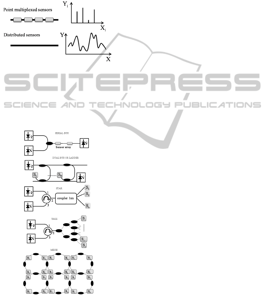
based on processing the value of the measurand
corresponding to each separate sensing element. On
the other hand, in the distributed sensors only one
sensing element is needed and the objective of the
signal processing is to recuperate the measurand as a
function of position along the sensing section.
Figure 3: Point multiplexed and distributed sensors.
There are diverse topologies for locating sensors
in a network. They can be divided into five basic
configurations, shown in figure 4 (where each one in
turn can be of a transmissive or reflective type):
serial, dual bus or ladder, star, tree or mesh
topologies (Lopez-Amo, 2011).
Figure 4: Multiplexing topologies for fiber optic sensors:
bus, ladder, star, tree and mesh.
3 DISTRIBUTED AND POINT
SENSORS
A great variety of physical and chemical parameters
can be measured by using point sensors. However,
here are hundreds of applications in structural health
monitoring (SHM) were the key parameters to be
measured are temperature and occasionally strain
and vibration. In those cases, distributed sensing is
an appropriate choice when many measurement
points are needed along a serial or linear
multiplexing topology. It is worth noticing the
difference between distributed and multi-point
sensing. Distributed refers to the ability to
simultaneously detect scale and location of a
measurand anywhere along a continuous length of
sensing fiber. Nevertheless, multi-point sensing
refers that the measurement is done at specific
locations with point sensors (Perez-Herrera, 2013).
Distributed measurements are also based on non-
linear scattering effects to evaluate a number of
different parameters. Rayleigh scattering comes
from the interaction between the light with refractive
index fluctuations in the fiber core that appear in
spatial scales much shorter than the light
wavelength. Because of that, Optical Time Domain
Reflectometry (OTDR) was developed initially as a
network diagnostic tool for optical fiber
telecommunication systems. Different means of
measuring this delay time leads to other time domain
techniques, like Optical Frequency Domain
Reflectometry (OFDR) or polarization domain
reflectometry (POTDR) (Jones, 1988).
Stimulated Raman scattering (SRS), for example,
is generated by the interaction of the propagating
light with molecular vibrations in the medium. On
the other hand, stimulated Brillouin scattering (SBS)
involves acoustic phonons. In this respect, both
scattering processes involve three-waves in which
the incident (pump) light is converted into (Stokes)
light of longer wavelength with an unavoidable
excitation of a molecular vibration (SRS) or an
acoustic phonon (SBS). However, there are a
number of significant differences between SBS and
SRS that lead to markedly diverse systems.
Raman backscatter systems have found real
applications niches such as monitoring tunnels and
have been also commercially presented from several
decades ago. These sensors are mostly simple to
install and provide temperature resolutions of the
order of 0.1 to 1 ºC within resolution lengths of
order of one meter over interrogation lengths
extending to tens of kilometers (Culshaw, 2004).
Brillouin scatter in contrast is usually used in the
PHOTOPTICS2015-InternationalConferenceonPhotonics,OpticsandLaserTechnology
142
frequency domain. The peak offset frequency for
Brillouin scattering is measured and is a unique
function of the acoustic velocity (and therefore
temperature and strain) in the optical fiber (Perez-
Herrera, 2013).
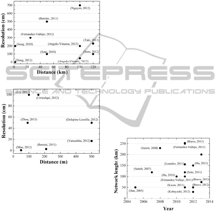
Figure 5: state of the art of long-range BOTDA sensors.
Figure 6: state of the art of high-resolution BOTDA
sensors.
One of the main drawbacks of this technique is
that the measurement range of these systems has a
trade-off between the measurement range and the
spatial resolution (Fernandez-Vallejo, 2012).
Consequently, present research in BOTDA sensors
has two different hot topics: long-range BOTDA
sensors, which are able to perform measurements in
tens of kilometers with meter resolutions, or high-
resolution sensors with centimeters spatial
resolution, but for relatively short-distances fibers.
Figures 5 and 6 summarize some of the advances in
long-range and high-resolution BOTDA sensors
respectively
4 HIGH PERFORMANCE
NETWORKS
The maximum measurement distance of fiber sensor
systems comes out to be a practical issue due to the
loss and noise and induced by the attenuation along
the fiber and the Rayleigh scattering respectively. A
number of diverse proposals have been
experimentally carried out in order to increase the
measuring distance of the fiber sensors.
For example, a 75-km long distance FBG sensor
system was experimentally demonstrated by (Fu,
2008). Though, every 25 km amplification was
needed which made the system more complex. An
ultra-long distance fiber Bragg grating sensor system
able to evaluate FBGs located 120 km far from
receiver position without using amplification was
demonstrated by (Saitoh, 2007). One year later, a
230 km FBTG sensor system using a high-speed
swept-wave- length light source using EDF
amplification was verified (Saitoh, 2008). (Leandro,
2011) presented and demonstrated a technique for
remote sensing of FBGs beyond 150 km combining
Brillouin, Raman, and erbium gain in a linear cavity
fiber laser. A long distance fiber laser system
composed by a random fiber laser with a reach of
200km able to multiple 11 optical fiber sensors
based on FBGs was proposed and experimentally
demonstrated by (Fernandez-Vallejo, 2013).
Figure 7: state of the art of the advances in remote sensing
systems for optical fiber sensors.
In most cases, complicated setups are employed
to reduce the noise effect in order to achieve longer
distance measurements. Nevertheless, (Fernandez-
Vallejo, 2011) proposed and experimentally
demonstrated a simple configuration able to detect
four multiplexed sensors located 250 km away
thanks to Raman amplification. In addition to this, a
FiberOpticSensorConfigurations
143

253 km ultra-long remote displacement sensor
system based on a fiber loop mirror and an OTDR
without using amplification was demonstrated by
(Bravo, 2011). Figure 7 illustrates some of the
advances in remote sensing systems for optical fiber
sensors over the last years.
5 ROBUST FIBER OPTIC
SYSTEMS
As it was previously pointed out, optical fiber sensor
networks provide sensing solutions for almost all
kind of applications and situations: from large
natural environments to large scale structures, such
as bridges and other civil constructions (Majumder,
2008).They are attracting an increasing interest
owing to their wide range of potential industrial
application in strategic sectors such as energy,
security (Fernandez-Vallejo, 2012), defense, or
transportation. Nevertheless, the constant operation
of the sensor network after accidental or malicious
harm is of increasing importance while the structure
being monitored is of high cost (power transmission
lines or oil pipelines); human protection is at risk
(nuclear plants or chemical storage locations) or
perimeter security is a concern (banks or airports)
(Li, 2004).
Four groups of protection to allow service to be
restored after a failure have been defined:
“dedicated” or “shared” protection, each of these has
sub-categories called “path” and “line” protection.
As a result, these four categories are dedicated line,
dedicated path, shared line and shared path (Pérez-
Herrera, 2014). The main difference between
dedicated and shared protection, derives from the
method the sensor unit is connected to the network.
Shared protection usually uses a switch although
dedicated protection employs an optical coupler.
Path protection and line protection differ in the
form of protection. In line protection, the sensors are
protected by the nearest switches to the failure, and
such switches are located in the sensor network itself
and not in the transmission/receiver node
(Ramamurthy, 2003). So, if a failure happens, the
network can reconfigure the path. Instead, in path
protection, each sensor is protected individually by
the switch positioned in the transmission or receiver
node which readdresses the information in the event
of a failure in the network.
Albeit most of optical sensor networks are based
on linear topologies, it is worth highlighting that
bus, star and ring topologies have been employed in
multipoint sensing systems too to overcome system
failure causing from breakpoints in the sensing
system. However, the sensing area is always
restricted in one dimension and not all types of
breakpoints can be restored. In order to solve this
disadvantage, a number of mesh sensing systems to
support more comprehensive sensing regions have
been recently proposed and experimentally
confirmed (Wu, 2010), (Peng, 2012). In these
topologies, the symmetric scheme warrants that the
proposed sensing system can be accessed from any
point.
Several optical sensor network based on optical
add-drop multiplexer (OADM) devices with a bus
configuration have been recently carried out (Bravo,
2013), (Rota-Rodrigo, 2013). These devices make it
possible to increase the amount of sensors in bus
networks in comparison with those that have optical
couplers and each sensor can be associated with a
different wavelength directly offered by each
OADM. In addition to this, these devices allow
networks to be developed for recovering operation
after failures and it performs self-diagnosis, that is,
the identification of the failed constituent(s) from the
patterns of surviving end-to-end connections at its
operating wavelengths (Perez-Herrera, 2012).
Thanks to this configuration it is possible to
coordinate self-diagnosis with protection switching
so as to reduce the momentary service interruption.
6 CONCLUSIONS
This work has reviewed the key fiber optic sensor
multiplexing main configurations and techniques as
well as some recent advances and trends in this field
of research. A summary of several high performance
networks has been presented. Finally, the current
trends in robust fiber optic sensor configuration have
been shown as well as the main records of
distributed and remote sensing fiber optics
topologies.
ACKNOWLEDGEMENTS
Financial support from the Spanish Comisión
Interministerial de Ciencia y Tecnología within
project TEC2013-47264-C2-2-R and FEDER funds
is acknowledged.
PHOTOPTICS2015-InternationalConferenceonPhotonics,OpticsandLaserTechnology
144

REFERENCES
López-Amo M., López-Higuera J.M., 2011 ‘Fiber Bragg
Grating Sensors: Research Advancements, Industrial
Applications and Market Exploitation’; Bentham
Science Publishers Ltd., Oak Park, Illinois, USA.
López-Higuera, J.M., 1998 Optical Sensors:
Fundamentals, current situation and future trends,
University of Cantabria, Spain.
Kersey, A.D. 1991 Fiber Optic Sensors: An Introduction
for Engineers and Scientists, E. Udd, Wiley, Hoboken,
NJ, USA.
Dandridge A. and Kirkendall C. 2002 Handbook of optical
fibre sensing technology, Chapter 21 John Wiley and
Sons, (, (Baffins Lane, Chichester, UK ).
Abad S., Lopez-Amo M., and Matias I.R., 2002 Handbook
of optical fibre sensing technology, Chapter 22. John
Wiley and Sons, (Baffins Lane, Chichester, UK).
Perez-Herrera, RA, Lopez-Amo, M 2013, ‘Fiber optic
sensor networks’, Invited Papers Optical Fiber
Technology, vol. 19, no. 6, pp 689-699.
Jones, JDC, McBride, R 1988 ‘Multiplexing optical fibre
sensors,’ Optical Fiber Sensors Technology, vol. 2.
Chapman & Hall, London.
Culshaw, B 2004, ‘Optical fiber sensor technologies:
opportunities and – perhaps - pitfalls,’ J. Lightwave
Technol. vol. 22, n. 1, pp. 39-50.
Nakajima, Y, Shindo, Y, Yoshikawa T, 2003 ‘Novel
concept as long-distance transmission FBG sensor
system using distributed Raman amplification’ in
Proc. 16th Int. Conf. Optical Fiber Sensors, Nara,
Japan, pp. 1-4.
Dong, Y, Zhang, H, Chen, L, Bao, X 2012, ‘A 2-cm-
spatial-resolution and 2-km-range Brillouin optical
fiber sensor using a transient differential pulse pair’
Appl. Opt., vol. 51, no. 9, pp. 1229–1235.
Fernandez-Vallejo, M, et al. 2012, ‘46 km long Raman
amplified hybrid double-bus network with point and
distributed Brillouin sensors’, IEEE Sensors Journal,
vol. 12, no. 1, pp. 184-188.
Angulo-Vinuesa, X, et al. 2012, ‘Raman-assisted Brillouin
optical time-domain analysis with sub-meter
resolution over 100 km’, Optics Express, vol. 20, no.
11, pp. 12147–12154.
Angulo-Vinuesa, X, et al., 2012, ‘100km BOTDA
temperature sensor with sub-meter resolution’ in Proc.
of SPIE 22nd International Conference on Optical
Fiber Sensors, vol. 8421, no. 842117.
Soto, MA, Bolognini, G, Pasquale, FD, Thévenaz, L 2010,
‘Long-range Brillouin optical time-domain analysis
sensor employing pulse coding techniques’ Meas. Sci.
Technol., vol. 21, no. 9, pp 094024.
Song, KY, Yang, S 2010, ‘Simplified Brillouin optical
time-domain sensor based on direct modulation of a
laser diode’ Opt. Express, vol. 18, no. 23, pp. 24012-
24018.
Nguyen, D.M., et al. 2012, ‘Sensitivity enhancement in
long-range distributed Brillouin fiber sensor using an
anti-Stokes single-sideband probe and a bidirectional
EDFA’ Photonics Global Conference, article
no.6458002.
Soto, MA, et al. 2012, ‘Simplex-Coded BOTDA Sensor
over 120-km SMF with 1-m Spatial Resolution
Assisted by Optimized Bidirectional Raman
Amplification’ IEEE Photon. Technol. Lett. vol. 24,
no. 20 pp. 1823-1826.
Taki, M, Soto, MA, et al. 2011, ‘Long-range BOTDA
sensing using optical pulse coding and single source
bi-directional distributed Raman amplification’, in
proc. of IEEE Sensors 10th, no 6127160, pp. 382–385.
Bernini, R, Minardo, A, Zeni, L 2011, ‘Long-range
distributed Brillouin fiber sensors by use of an
unbalanced double sideband probe’ Opt. Express, vol.
19, no. 24, pp. 23845–23856.
Zhou, DP, Li, W, Chen, L, Bao, X 2013, ‘Distributed
Temperature and Strain Discrimination with
Stimulated Brillouin Scattering and Rayleigh
Backscatter in an Optical Fiber’ Sensors vol. 13, no. 2
pp. 1836-1845.
Mao, Y, Guo, N, Yu, KL, Tam, HY 2012, ‘1-cm-Spatial-
Resolution Brillouin Optical Time-Domain Analysis
Based on Bright Pulse Brillouin Gain and
Complementary Code’ IEEE Photonics Journal, vol.
4, no. 6, pp. 2243-2248.
J. Urricelqui, A. Zornoza, M. Sagues, A. Loayssa, 2012
‘Dynamic BOTDA measurements using Brillouin
phase-shift,’ Proc of SPIE 22nd International Conf. on
Optical Fiber Sensors, vol. 8421, No. 842125.
Yamashita, RK, He, Z, Hotate, K 2012, ‘Spatial resolution
improvement based on intensity modulation in
measurement of Brillouin dynamic grating localized
by correlation domain technique,’ Proc. of SPIE
OFS22, vol. 8421, No. 84219H, 2012.
S. Delepine-Lesoille, X. Phéron, J. Bertrand, et al. 2012,
‘Industrial Qualification Process for Optical Fibers
Distributed Strain and Temperature Sensing in Nuclear
Waste Repositories’ Journal of Sensors, vol. 2012, no.
369375, 9 pages.
Bernini, R, Minardo, A, Zeni, L 2011, ‘Lecture notes in
electrical engineering,’ 16
th
Conference on Italian
Association of Sensors and Microsystems, vol. 109,
pp. 235-239.
Fry, ES 2012 ‘Remote sensing of sound speed in the ocean
via Brillouin scattering’ in: Proc. of SPIE, vol. 8372,
no. 837207.
Fu, HY, et al. 2008, ‘A novel fiber Bragg grating sensor
configuration for long-distance quasi distributed
measurement’, IEEE Sensors Journal, vol. 8, no. 9,
pp. 1598-1602.
Saitoh, T, Nakamura, et al. 2007, ‘Ultra-Long-Distance
Fiber Bragg Grating Sensor System’ IEEE Photon.
Technol. Lett., vol. 19, no. 20, pp. 1616–1618.
Saitoh, T, Nakamura, K, et al. 2008, ‘Ultra-long-distance
(230 km) FBG sensor system,’ in: Proc. SPIE, vol.
7004, pp. 70046C-4.
Leandro, D, et al. 2011, ‘Remote (155 km) Fiber Bragg
Grating Interrogation Technique Combining Raman,
Brillouin, and Erbium Gain in a Fiber Laser’, IEEE
Photon. Technol. Lett., vol. 23, no. 10, pp. 621–623.
FiberOpticSensorConfigurations
145

Fernandez-Vallejo, M, Bravo, M, Lopez-Amo, M 2013
‘Ultra-long laser systems for remote fiber Bragg
gratings arrays interrogation,’ IEEE Photonics
Technology Letters, vol. 25, no. 14, pp. 1362-1364.
Fernandez-Vallejo, M, et al. 2011, ‘Remote (250 km)
Fiber Bragg Grating Multiplexing System’ Sensors,
vol. 11, no. 9, pp. 8711–8720.
Bravo, M, Baptista, JM, Santos, JL, Lopez-Amo, M,
Frazão, O 2011, ‘Ultralong 250 km remote sensor
system based on a fiber loop mirror interrogated by an
optical time-domain reflectometer’ Opt. Lett., vol. 36,
no. 20. pp. 4059–4061.
Han, YG, Tran, TVA, Kim, SH, Lep, SB 2005,
‘Development of a multiwavelength Raman fiber laser
based on phase-shifted fiber Bragg gratings for long-
distance remote-sensing applications’ Opt. Lett. vol.
30, no. 10, pp. 1114–1116.
Hu, J, Chen, Z, Yang, X, Ng, J, Yu, C 2010, ‘100-km
Long Distance Fiber Bragg Grating Sensor System
Based on Erbium-Doped Fiber and Raman
Amplification’ IEEE Photon. Technol. Lett., vol. 22,
no. 19, pp. 1422–1424.
Soto, MA, Faralli, S, Taki, M, Bolognini, G, Pasquale, FD
2011 ‘BOTDA sensor with 2-m spatial resolution over
120 km distance using bi-directional distributed
Raman amplification,’ Proc. of the SPIE OFS21, vol.
7753, pp. 775325.
Fernandez-Vallejo, M, Leandro, D, Loayssa, A, Lopez-
Amo, M 2011, ‘Fiber Bragg Grating interrogation
technique for remote sensing (100km) using a hybrid
Brillouin-Raman fiber laser,’ Proc. of SPIE OFS21,
vol. 7753, pp. 77537I-1–77537I-4.
Kwon, OJ, Kim, HJ, Yoon, MS, Park, S, Shim, Y, Lee,
SB, Han, YG 2011, ‘Long distance simultaneous
measurement of bending and temperature based on a
dual-wavelength Raman fiber laser,’ Proc. of SPIE,
vol. 7753, no. 77531D.
Hu, J, Chen, Z, Yu, C 2012, ‘150-km Long Distance FBG
Temperature and Vibration Sensor System Based on
Stimulated Raman Amplification’ J. Ligthwave
Technol., vol. 30, no. 8, pp. 1237–1243.
Kobayashi, H, Tsuzuki, T, Onishi, T, et al. 2012,
‘Suppression of Instability on Sensing Signal of
Optical Pulse Correlation Measurement in Remote
Fiber Sensing,’ Journal of Sensors, vol. 2012,
no.107847.
Bravo, M, Fernández-Vallejo, M, Lopez-Amo, M 2012,
‘Hybrid OTDR-fiber laser system for remote sensor
multiplexing’ IEEE Sens. J. vol. 12, no. 1, pp.174-178.
Bravo, M, et al. 2013, ‘Multiplexing of six micro-
displacement suspended-core Sagnac interferometer
sensors with a Raman-Erbium fiber laser’ Opt.
Express, vol. 21, no. 3, pp. 2971–2977.
Fernandez-Vallejo, M, Bravo, M, Lopez-Amo, M 2013,
‘Ultra-long laser systems for remote fiber Bragg
gratings arrays interrogation’, IEEE Photon. Technol.
Lett., vol. 25, no. 14, pp. 1362–1364.
Majumder, M 2008, ‘Fiber Bragg gratings in structural
health monitoring-Present status and applications’,
Sensors Act. A: Physical vol. 147, no. 1, pp. 150–164.
Fernandez-Vallejo, M 2012, ‘46-km-Long Raman
Amplified Hybrid Double-Bus Network With Point
and Distributed Brillouin Sensors’ IEEE Sensors
Journal, vol. 12, no. 1, pp. 184-188.
Li, H 2004, ‘Recent applications of fiber optic sensors to
health monitoring in civil engineering’, Engineering
Structures, vol. 26, pp. 1647–1657.
Pérez-Herrera, R. A., Lopez-Amo, M. 2014 ‘Robust Fiber-
Optic Sensor Systems’ Conference Paper Optical
Fiber Sensors II (SeW2C) (pp. SeW2C-1) Optical
Society of America.
Ramamurthy, S 2003, ‘Survivable WDM mesh networks’
Journal of Lightwave Technology, vol. 21, pp.870-
883.
Wu, CY 2010, ‘Three-dimensional mesh-based multipoint
sensing system with self-healing functionality,’ IEEE
Photon. Technol. Lett., vol. 22, pp. 565–567.
Peng, PC 2012, ‘Novel optical add-drop multiplexer for
wavelength-division-multiplexing networks,’ Opt.
Comm., vol. 285, pp. 3093-3099.
Bravo, M, Fernandez-Vallejo, M, Lopez-Amo, M,
Kobelke, J, Schuster, K. 2013 ‘Fiber optical sensor
networks based on OADM devices with a bus
configuration’, Proceedings of SPIE, vol. 8794, no.
87943V.
Rota-Rodrigo, S, Perez-Herrera, R.A, et al. 2013,
‘Multiwavelength Fiber Ring Laser based on Optical
Add-Drop Multiplexers and a Photonic Crystal Fiber
Sagnac interferometer’, Optics & Laser Technology,
vol. 48, no. pp. 72–74.
Perez-Herrera, RA, Urquhart, P, Schlüter, M, et al. 2012,
‘Optical Fiber Bus Protection Network to Multiplex
Sensors: Experimental Validation of Self-Diagnosis,’
IEEE Sensors Journal, vol. 12, no. 9, pp. 2737-2743.
PHOTOPTICS2015-InternationalConferenceonPhotonics,OpticsandLaserTechnology
146
