
FDMD: Feature-Driven Methodology Development
Rezvan Mahdavi-Hezave and Raman Ramsin
Department of Computer Engineering, Sharif University of Technology, Azadi Avenue, Tehran, Iran
Keywords: Software Development Methodology, Situational Method Engineering, Requirements Engineering,
Feature-Driven Development.
Abstract: Situational Method Engineering (SME) is a branch of software engineering which helps develop bespoke
methodologies to fit the specific characteristics of the software project at hand. As in software development,
SME too involves rigorous Requirements Engineering (RE), so much so that if requirements elicitation and
definition is mishandled in any way, methodology development will most likely fail as a result. In this
paper, we propose a Feature-driven methodology for SME; in this SME methodology, the requirements of
the target methodology are captured as Features. First introduced in the agile FDD (Feature-Driven
Development) methodology, Features are fully object-oriented and provide all the benefits that the object-
oriented paradigm has to offer. Due to the object-oriented nature of Features and the rest of its deliverables,
our proposed Feature-Driven Methodology Development (FDMD) process is fully seamless; this also
facilitates the development of tool support for the methodology which is produced by applying FDMD.
1 INTRODUCTION
Various software development methodologies exist,
but software engineers have long realized that they
cannot use an existing methodology for all project
situations, as every software development project
has its own specific characteristics. As a
consequence, a branch of software engineering–
known as Situational Method Engineering (SME)–
has emerged, which helps develop bespoke
methodologies to fit the specific characteristics of
project situations (Henderson-Sellers and Ralyté,
2010). As in software development, SME involves
rigorous Requirements Engineering (RE), concerned
with the elicitation of the functional and non-
functional requirements of the target methodology.
Numerous approaches have been proposed for
RE in software development (Van Lamsweerde,
2009). In contrast, the RE methods that are currently
practiced in SME are still in their infancy. Most of
the research conducted on SME is focused on the
selection and assembly of method fragments to
produce bespoke methodologies; however, selection
and assembly should satisfy specific requirements;
RE thus becomes particularly important in SME.
In this paper, we propose a feature-driven SME
methodology in which methodology requirements
are described in an object-oriented format, using the
notion of feature which was first introduced in the
agile Feature-Driven Development (FDD)
methodology. Object-oriented description of
requirements promotes the seamlessness of the
methodology development process and facilitates the
development of tool support for the developed
methodology. Viewing and modeling a methodology
as a set of objects is not novel: It already exists in
metamodels such as the Open Process Framework
(Firesmith, 2014); however, our proposed Feature-
Driven Methodology Development (FDMD) method
is novel in that it is a full-lifecycle SME
methodology that incorporates object-orientation
into all of its activities, especially RE.
The rest of this paper is organized as follows:
Section 2 provides an overview of the research
background; Section 3 introduces the proposed
methodology (FDMD) and provides detailed
descriptions for its phases; Section 4 presents an
example of enacting the methodology; Section 5
provides a criteria-based evaluation of the
methodology; and Section 6 presents the conclusions
and suggests ways for furthering this research.
2 RESEARCH BACKGROUND
We will first briefly survey the related research.
229
Mahdavi-Hezave R. and Ramsin R..
FDMD: Feature-Driven Methodology Development.
DOI: 10.5220/0005384202290237
In Proceedings of the 10th International Conference on Evaluation of Novel Approaches to Software Engineering (ENASE-2015), pages 229-237
ISBN: 978-989-758-100-7
Copyright
c
2015 SCITEPRESS (Science and Technology Publications, Lda.)

2.1 RE, FDD and Features
RE refers to the process of elicitation, description,
validation and management of requirements. In
software engineering, RE has long been the focus of
scrutiny and research (Van Lamsweerde, 2009).
Feature-Driven Development (FDD) is an agile
methodology which uses the notion of feature to
express functional requirements (Palmer and
Felsing, 2001). A feature is typically expressed as:
<action> <result> <object>; e.g., ‘check the
availability of seats on a flight’. Due to their object-
oriented nature, features should be elicited after
identifying the problem domain classes. Each feature
belongs to one feature-set (activity), expressed as:
<action>-ing a(n) <object>; e.g., ‘reserving a seat’.
Each feature-set belongs to one area, expressed as:
<object> management; e.g., ‘ticket management’.
2.2 RE in SME
SME is a subfield of Method Engineering
(Brinkkemper, 1996) which aims at developing
bespoke methodologies for project situations
(Henderson-Sellers and Ralyté, 2010). A SME
process framework has been proposed in (Asadi and
Ramsin, 2009), which can be instantiated to produce
a bespoke SME methodology; we have used this
framework for developing our proposed feature-
driven SME methodology (FDMD).
In SME, RE is focused on the engineering of
methodology requirements based on the
characteristics of project situations. Alternative
strategies for RE in SME have been proposed in
(Ralyté, 2002). A flexible RE framework for SME
has been proposed in (Olsson et al., 2005), and an
iterative criteria-based approach for RE in SME has
been proposed in (Ramsin and Paige, 2010).
2.3 Using Features for RE in SME
Using features in FDD has resulted in a seamless
(fully object-oriented) methodology. Using features
in SME is of the same potential benefits: The
methodology development process would be
seamless, and it would benefit from the merits of
object-orientation: 1) Maintainability; 2) reusability;
and 3) facilitated production of tool support, as the
object-oriented models of the methodology could be
reused for implementing tools.
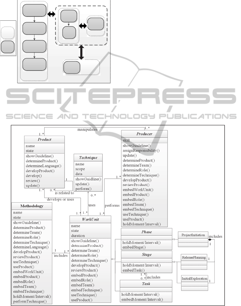
3 FDMD: FEATURE-DRIVEN
METHODOLY DEVELOPMENT
In this section, we will describe our proposed
Feature-Driven Methodology Development (FDMD)
process (Figure 1). FDMD consists of three phases:
Initiation, Methodology Construction, and
Termination. As explained in the rest of this section,
each phase consists of nested stages, which in turn
consist of finer-grained stages and/or atomic tasks.
3.1 Initiation Phase
The goal of this phase is to specify the features and
the framework (architecture) of the methodology.
3.1.1 Select a Suitable Framework for the
Target Methodology (Stage)
Organizational domain experts, software engineers
(users of the target methodology), method engineers
(who apply the FDMD process), and the SME
project manager, collectively decide on a suitable
framework for the target methodology; this
framework provides the general lifecycle of the
methodology, and will be used for identifying the
classes. It might be decided to reuse generic process
frameworks; examples of such frameworks have
been proposed in (Ambler, 1998), (Kouroshfar et al.,
2009), (Babanezhad et al., 2010), and (Biglari and
Ramsin, 2012).
3.1.2 Specify Classes (Stage)
The classes of the target methodology are identified
in this stage. The tasks are explained below:
Form Class Extraction Teams (Task) — The
project manager forms teams of method engineers,
software engineers (users), and domain experts.
Extract Classes (Task) — Class extraction teams
determine methodology classes by using available
repositories of classes (Firesmith, 2014) and the
selected framework. Teams work in parallel to each
produce a Class Diagram for the target
methodology. Key classes are: Work Unit (activities
that producers perform to develop the products),
Product (artefacts that are produced or used in a
methodology), and Producer (people who produce or
manipulate the products by performing work units).
Specify Final Set of Classes (Task) — The class
diagram is finalized by integrating the diagrams
produced by the different teams.
ENASE2015-10thInternationalConferenceonEvaluationofNovelSoftwareApproachestoSoftwareEngineering
230

Figure 1: FDMD process.
3.1.3 Describe Requirements by Features
(Stage)
The features of the target methodology are elicited.
Extract Situational Factors (Task) — The project
manager elicits the characteristics of the project
situation as situational factors. Existing sets of
situational factors can be used for this purpose; such
as the set of situational factors proposed for agile
development (Abad et al., 2012). Situational factors
are given values based on the project situation. Non-
functional requirements should also be defined in
this task: They can be derived from situational
factors, or be specified by the customer; an example
of a mapping from factors to non-functional
requirements is shown in Table 1 (based on (Abad et
al., 2010)).
Categorize Features (Task) — An initial grouping
(architecture) is determined for the features. Figure 2
shows the grouping suggested by FDMD, which will
be refined based on the selected framework and the
classes identified. The work units of the framework
will be mapped to phase-, stage-, and task groups.
Form Feature Teams (Task) — The project
manager forms teams of method engineers, software
engineers, and domain experts. Feature groups
(phase/stage/task) are assigned to the teams to elicit.
Table 1: Example of a mapping from a situational factor to
non-functional requirements.
Situational Factor
(Value)
Corresponding
Non-functional Requirements
Degree of importance of
the project to the
environment (High)
Traceability to Requirements,
Maintainability, Risk Management,
Seamlessness
Specify Features (Task) — The features of each
feature group are elicited and described based on
predefined sets of patterns: The feature patterns of
Table 2 are structural, as they translate to the
structure (constituents) of the target methodology,
whereas the patterns of Table 3 are behavioural, in
that they translate to the ordering of activities in the
methodology. Feature teams base their work on the
situational factors, and make use of available
mappings of situational factors and non-functional
requirements (such as seamlessness) to features;
Tables 4 and 5 show examples of such mappings
(adapted from (Abad, Sadi, and Ramsin, 2010)).
Features are checked to make sure that their
objects conform to the selected framework and the
class diagram; also, it should be verified that all the
behavioural features (orderings) related to each
feature group have indeed been specified. New
classes and operations are added to the class diagram
as required (based on the features and their objects).
Develop the Features Document (Task) — The
project manager integrates all the features developed
by the feature teams into a “features document”.
Check Consistency among Features (Task) —
Features are checked for inconsistencies and
conflicts, and the problems are resolved.
Phase Features
Stage Features
Task Features
Stage Features
Task Features
Legend
A group of work unit
features
Figure 2: Suggested grouping for methodology features.
FDMD:Feature-DrivenMethodologyDevelopment
231

Table 2: Structural feature patterns.
Feature Action Result
a
Object
Show
Show
Guidelines and
Conventions
Phase, Stage, Task,
Moment/Interval,
Technique, Producer,
Product, Language
Example: Show guideline for “organize a team” task.
Specify/
Update
Specify
Technique,
Producer, Product,
and Language
(or an attribute)
Phase, Stage, Task,
Moment/Interval,
Team, Product
Example: Specify facilitator for planning team.
Review
Review Product
Phase, Stage, Task,
Moment/Interval
Example: Review design models during design
review.
Develop
Develop Product
Moment/Interval,
Phase, Stage, Task,
Product
Example: Develop project plan during planning.
Embed
Embed
Phase, Stage,
Task,
Moment/Interval,
Technique,
Producer, Product
Methodology, Phase,
Stage, Task,
Moment/Interval
Example: Embed feasibility analysis into analysis.
Use
Use
Technique,
Product
Phase, Stage, Task,
Moment/Interval
Example: Use pair programming for implementation.
Hold
Hold Moment/Interval Phase, Stage, Task
Example: Hold review meeting at the design phase.
Assign
Assign Responsibility Producer
Example: Assign analysis responsibility to the analyst.
a.
Note that Results are not necessarily related to Objects; e.g., in ‘Specify’,
the ‘team’ as the Result is not related to the ‘team’ as the Object.
Table 3: Behavioural feature patterns.
Precedent Constraint Antecedent Action Feature
Phase,
Stage, Task
Sequential
Constraint
Phase,
Stage, Task
Perform
Performing
sequentially
Example: Perform planning after feasibility study.
Phase,
Stage, Task
Parallel
Constraint
Phase,
Stage, Task
Perform
Performing
in parallel
Example: Perform testing in parallel with coding.
Table 4: Examples of proposed mappings of “project
organization” situational factors to features.
Features
Situational Factor
(Value)
- Use pair programming in coding.
- Use side-by-side programming in
coding.
Developers’
technical expertise
(Uneven)
- Develop a team calendar at initiation.
- Develop Wiki pages at initiation.
- Hold introductory meetings at initiation.
- Use conference-calls at daily meetings.
Distribution of
development teams
(Geographically
Distributed)
- Use the “move people around”
technique for managing development
teams.
- Use “pair programming” in coding.
Distribution of skills
(Uneven)
Table
5: Features corresponding to “seamlessness”.
Features Feature Type
- Develop the object model in the analysis phase . Develop
- Hold design sessions in the build stage.
- Hold quick design sessions in the build stage.
Hold
3.2 Methodology Construction Phase
The target methodology is produced in three stages.
3.2.1 Plan for Construction Engine (Stage)
The project manager forms development teams of
method engineers, software engineers (ambassador
users), and domain experts; feature groups are then
prioritized and assigned to each development team.
3.2.2 Construction Engine (Stage)
Development teams perform the iterative substages
of the engine until all the features are realized.
Develop Methodology (Substage) — Each
development team iteratively realizes the features
assigned to it. The tasks are as follows:
Prioritize and Select Features (Task) — Feature
priorities are reviewed and revised at the start of the
iteration. The team then selects a group of high-
priority features to realize in the current iteration.
Behavioural Modeling (Task) — For each feature
in the selected feature group, a Sequence Diagram is
produced which shows the object interactions
necessary to realize that feature.
Update Classes (Task) — After determining the
role of each object in feature realization, new
operations and classes are added to the class
diagram.
Process Development (Task) — A model of the
methodology is created/updated to realize the
selected feature group. The methodology is modeled
in a Process Diagram; FDMD uses the UML4SPM
notation for this purpose (Bendraou et al., 2005).
The selected feature group, the updated class
diagram, and the produced sequence diagrams (the
object-oriented model chain) are used as sources for
producing the process diagram. FDMD proposes the
mapping rules of Table 6 for producing the process
diagram from these sources.
Specify Reusable Components (Task) — Reusable
features, classes, and diagrams are identified and
stored in a repository to be reused in future projects.
Requirements Change Management (Task) —T
he list of features is updated, and changes are
logged.
ENASE2015-10thInternationalConferenceonEvaluationofNovelSoftwareApproachestoSoftwareEngineering
232

Table 6: Proposed rules for mapping the elements of the object-oriented model chain to elements of the process diagram.
Mapping Rule (from source to process diagram) Source
Groupings of features will be mapped to the general structure of the process diagram. Grouping
Features
An actor in the real world will be mapped to a role in the relevant element of the process diagram.
Structural
If the result or object is a product, it will be mapped to an input, output or intermediate product.
If the result or object is a work unit, it will be mapped to a work unit.
If the result or object is a technique, it will be mapped to a technique of a work unit.
If the result or object is a language, it will be mapped to a product or process.
If two work units are performed sequentially, they should be performed sequentially in the process diagram.
Behavioural
If two work units are performed in parallel, they should be defined so in the process diagram (by using fork and join).
If a work unit is performed in parallel with all other units, it is shown as an umbrella activity in the process diagram.
If two producers are in an association relationship, they are both mapped to the roles of their related work units.
Class diagram
If two products are in an association relationship, they are both mapped to the products of their related work units.
If two work units are in an aggregation relationship, the ‘whole’ will contain the ‘part’ in the process diagram.
If a producer and a product are in an association relationship, and both of them are related to the same work unit, then
the product will be a product of that work unit in the process diagram, and the producer will be a role in that unit.
If a work unit and a product are in an association relationship, they will be related in the process diagram.
If a work unit and a producer are in an association relationship, the producer will be mapped to a role of the work
unit.
If a work unit and a technique are in an association relationship, they will be related in the process diagram.
Classes whose objects are used in the sequence diagrams are mapped to the relevant element of the process diagram.
Sequence
diagram
Operations in sequence diagrams are mapped to the relevant processes in the process diagram.
General process diagram rules:
- Roles in each process diagram element are added to the roles of the coarser-grained process diagram elements that contain that element.
- Preconditions in each process diagram element are added to the preconditions of the process diagram elements that contain that
element.
Hold Review Meeting (Task) — Iteration products,
and the FDMD process, are reviewed and revised.
Implement Tool Support (Optional Substage) —
A suitable implementation environment is first
selected. Solution-domain (design) classes are added
to the class diagram, and sequence diagrams are
extended with design objects. Tool(s) are then
developed based on these design diagrams.
3.2.3 Conclude Construction (Stage)
The project manager integrates the process diagrams
developed by the teams; the final diagram is then
checked for inconsistencies.
3.3 Termination Phase
The product is tested, deployed and maintained.
3.3.1 Test (Stage)
The produced methodology is tested before delivery:
It is reviewed by methodology experts, and validated
against the requirements. Bugs are fixed through
further runs of the construction engine.
3.3.2 Conduct Post-mortem Activities
(Stage)
This stage consists of two post-mortem activities:
The lessons learnt are documented, and the
development process is revised for future projects.
3.3.3 Deliver and Maintain (Stage)
A Methodology Document is produced which
contains detailed information on the produced
methodology, and users (software engineers) are
trained on its proper enactment. The methodology is
then enacted in the customer organization. The
problems that occur during the enactment of the
methodology are identified and resolved.
4 EXAMPLE
We will demonstrate the use of the FDMD process
via partial development of an agile methodology.
During the Initiation phase, the generic agile
process framework proposed in (Abad, Sadi, and
Ramsin, 2010) has been selected (Figure 3). Based
on the selected framework and the set of classes
suggested by (Firesmith, 2014), a class diagram has
then been produced (Figure 4 shows an example).
We have specified one situational factor for this
example: “Degree of importance of the project to the
environment”, which has been evaluated as “High”.
Furthermore, “Risk management” has been
determined as a non-functional requirement.
The situational factor mentioned above maps to
several features, one of which has been chosen for
FDMD:Feature-DrivenMethodologyDevelopment
233
this example: “Develop a domain model in the
‘understand domain’ task”.
Legend
Phase
Stage
Project
Initiation
Project
Termination
Development
Review
Project Start-up
Requirements
Elicitation
Initial
Exploration
Build
Iteration
Planning
Reflection
Project
Wrap-up
Release
Planning
Figure 3: Agile process framework used in the example.
During the Methodology Construction phase, a
sequence diagram is developed for the above feature
(Figure 5); the class diagram is then enriched with
the new operations identified. Based on the object-
oriented model chain developed, a process diagram
is produced through applying the relevant mapping
rules; Figure 6 shows the final process diagram
(after several iterations).
5 CRITERIA-BASED
EVALUATION
The evaluation presented here is based on evaluation
criteria which assess the general characteristics
(Hesari et al., 2010), SME-related characteristics
(Zakerifard and Ramsin, 2014), RE-related
characteristics (Taromirad and Ramsin, 2008), and
Feature-related characteristics of the proposed
methodology (FDMD). The results of the evaluation
are shown in Table 7; the results show that FDMD
has adequately addressed the issues assessed by the
criteria. FDMD has also been evaluated by
application in a major Iranian insurance company,
and the results have been encouraging.
Figure 4: Partial Class diagram for the example.
ENASE2015-10thInternationalConferenceonEvaluationofNovelSoftwareApproachestoSoftwareEngineering
234

Figure 5: Sequence diagram for “Develop a domain model in the ‘understand domain’ task”.
Figure 6: Process diagram of the example.
6 CONCLUSIONS AND FUTURE
WORK
We have proposed FDMD as a concrete feature-
driven methodology for SME, which uses features
for specifying the requirements. Due to their object-
oriented nature, features can promote seamlessness,
facilitate the development of the target methodology
and tool support, and enhance maintainability and
reusability. FDMD is novel in that: 1) FDD-style
features have never been used in SME; and 2)
FDMD is the first SME method to use the object-
oriented approach to its full potential.
Future work will focus on using FDMD in more
industrial case studies to further identify its strengths
and weaknesses. A parallel strand can focus on
exploring the merits of this approach in developing
tool support for the methodologies produced,
especially through the production of CASE tools,
and/or integration into Process-centered Software
Engineering Environments (PSEEs).
ACKNOWLEDGEMENTS
We wish to thank Mr. Mohammad Reza Besharati
for reviewing the Example section.
sd understandDomain
Domain Expert
هژورپ ريدم
aRole
:DomainExpert
هژورپ ريدم
aTask
:UnderstandDomain
هژورپ ريدم
aProduct
:DomainModel
showGuideline(UnderstandDomainTask)
understandDomain()
develop(domainModelName, description)
»create«
understandDomain()
developProduct(domainModelName , description)
developProduct(domainModelName , description)
:DomainModel
FDMD:Feature-DrivenMethodologyDevelopment
235
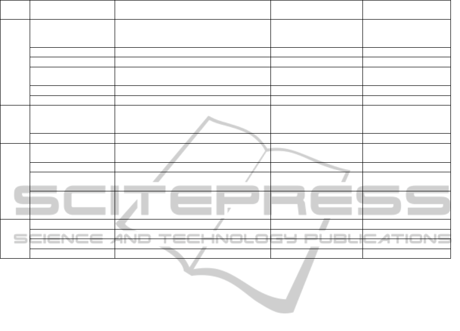
Table 7: FDMD evaluation results.
FDMD Evaluation
Result
Possible Values Description Criterion Group
RE, Analysis, Design,
Implementation, Test,
Maintenance
Phases of the generic
development life cycle that
are covered.
Which phases of the generic development
lifecycle are covered by the development
process?
Coverage of the generic
development lifecycle
activities
General criteria
Yes (due to using features)Yes, No Is the transition between phases seamless? Seamless transition
Yes (due to using features)Yes, No Is the transition between phases smooth? Smooth transition
Yes Yes, No
Are the products tangible, understandable, and
testable to end users?
Visibility, testability and
tangibility of artifacts
Yes Yes, No Are users involved in the development process?Active user involvement
Yes Yes, No Is the development process practicable? Practicability
Assembly-based,
paradigm-based,
extension-based
Assembly-based, paradigm-
based, extension-based,
road-map-driven, hybrid
Which approaches are supported for developing
the methodology?
Methodology engineering
approach
SME-
related
criteria
Yes Yes, No Is requirements engineering addressed? Support for RE activities
Feature
User story, Feature, Use-
case , Usage scenario
How are the requirements specified?
Requirements
specification format
RE-related criteria
Yes Yes, No Does the process allow requirements change? Requirements change
Grouping of features
Methods of complexity
management
How is complexity management applied to the
requirements?
Complexity management
Functional value
Architectural value,
Functional value, Business
value, Development risk
On what basis are the requirements prioritized?
Requirements
prioritization
Yes Yes, No Does the process support planning by features?Planning by feature
Feature-
related
criteria
Yes Yes, No Does the process support designing by features?Designing by feature
Yes Yes, No Is implementation driven by features? Implementing by feature
Yes Yes, No Does the process support testing by features? Testing by feature
REFERENCES
Henderson-Sellers, B., Ralyté, J., 2010. “Situational
Method Engineering: State-of-the-Art Review,”
Journal of Universal Computer Science, vol. 16, no. 3,
pp. 424–478.
Van Lamsweerde, A., 2009. Requirements engineering:
From system goals to UML models to software
specifications. John Wiley & Sons.
Firesmith, D., 2014. OPEN Process Framework (OPF)
Repository Organization (OPFRO) Website. Available
at: http://opfro.org/. (Accessed: 22-Apr-2014).
Palmer, S. R., Felsing, M., 2001. A practical guide to
feature-driven development. Pearson Education.
Brinkkemper, S., 1996. “Method engineering: Engineering
of information systems development methods and
tools,” Information and Software Technology, vol. 38,
no. 4, pp. 275–280.
Asadi, M., Ramsin, R., 2009. “Patterns of Situational
Method Engineering,” in Proceedings of SERA'09, pp.
277–291.
Ralyté, J., 2002. “Requirements Definition for the
Situational Method Engineering,” in Proceedings of
EISIC'02, pp. 127–152.
Olsson, T., Doerr, J., Koenig, T., Ehresmann, M., 2005.
“A flexible and pragmatic requirements engineering
framework for SME,” in Proceedings of SREP'05, pp.
1–12.
Ramsin, R., Paige, R. F., 2010. “Iterative criteria-based
approach to engineering the requirements of software
development methodologies,” IET Software, vol. 4,
no. 2, pp. 91–104.
Ambler, S. W., 1998. Process patterns: Building large-
scale systems using object technology. Cambridge
University Press.
Kouroshfar, E., Shahir, H. Y., Ramsin, R., 2009. “Process
patterns for component-based software development,”
in Proceedings of CBSE'09, pp. 54–68.
Babanezhad, R., Bibalan, Y. M., Ramsin, R., 2010.
“Process Patterns for Web Engineering,” in
Proceedings of COMPSAC'10, pp. 477–486.
Biglari, B., Ramsin, R., 2012. “Generic Process
Framework for Developing High-Integrity Software,”
in Proceedings of SoMeT'12, pp. 73–88.
Abad, Z. S. H., Alipour, A., Ramsin, R., 2012. “Enhancing
Tool Support for Situational Engineering of Agile
Methodologies in Eclipse,” in Proceedings of
SERA'12, pp. 141–152.
Abad, Z. S. H., Sadi, M. H., Ramsin, R., 2010. “Towards
tool support for situational engineering of agile
methodologies,” in Proceedings of APSEC'10, pp.
326–335.
Bendraou, R., Gervais, M., Blanc, X., 2005. “UML4SPM:
A UML2.0-based metamodel for software process
modelling,” in Proceedings of MoDELS'05, pp. 17-38.
Hesari, S., Mashayekhi, H., Ramsin R., 2010. “Towards a
general framework for evaluating software
development methodologies,” in Proceedings of
COMPSAC’10, pp. 208–217.
Zakerifard, H., Ramsin, R., 2014. “UCDMD: Use Case
ENASE2015-10thInternationalConferenceonEvaluationofNovelSoftwareApproachestoSoftwareEngineering
236

Driven Methodology Development,” in Proceedings
of ICSEA’14, pp. 434-440.
Taromirad, M., Ramsin, R., 2008. “CEFAM:
Comprehensive evaluation framework for agile
methodologies,” in Proceedings of SEW’08, pp. 195–
204.
FDMD:Feature-DrivenMethodologyDevelopment
237
