
R
2
BA
Rationalizing R2RML Mapping by Assertion
Rita Berardi
1
, Vania Vidal
2
and Marco A. Casanova
1
1
Departamento de Informática, Pontifícia Universidade Católica do Rio de Janeiro, Rio de Janeiro, Brazil
2
Universidade Federal do Ceará, Fortaleza, Ceará, Brazil
Keywords: Customized R2RML Mapping, Design Rationale.
Abstract: The W3C RDB2RDF working group proposed R2RML as a standard mapping language that defines how to
publish data stored in relational databases as RDF triples. However, R2RML mappings are sometimes diffi-
cult to understand, which may affect the users’ understanding of the transformations the original data suffer
until published as RDF triples. To address this problem, this paper extends a semi-automatic method to define
R2RML mappings to include design rational, thereby helping publishers to document the design process and
final users to consume the published data. The paper also proposes to use the design rationale captured to
enrich the representation of the original data in RDF, which ontology matching algorithms may use to find
potential links to other existing vocabularies, thereby promoting interoperability.
1 INTRODUCTION
Two main approaches are widely used for mapping
relational databases into RDF: the direct mapping ap-
proach, where the database schema is directly
mapped to ontology elements (Sequeda et. al., 2011),
and the customized mapping approach, where the
schema of the RDF may differ significantly from the
original database schema. As an alternative to propri-
etary mapping languages, the W3C RDB2RDF
Working group proposed R2RML as a standard map-
ping language (Das, et. al., 2012).
R2RML mappings allow the designer to express
customized transformations over the original data,
which may affect how the published data is con-
sumed. Hence, it would help the user understanding
such transformations if a transparency layer were
added to the publishing process. Adding transparency
would also help the data publisher to trace all the
RDB-to-RDF process for maintenance purpose.
This paper therefore proposes a strategy, called
R
2
BA, to achieve transparency. R
2
BA couples design
rationale with a semi-automatic method to define
R2RML mappings, called RBA (R2RML by asser-
tion) (Vidal et. al., 2014). RBA adopts correspond-
ence assertions as a convenient way to manually spec-
ify R2RML mappings and incorporates an automatic
procedure to generate SQL Views and R2RML map-
pings from the correspondence assertions. Intuitively,
R
2
BA rationalizes the R2RML mappings, in the sense
that it makes explicit all the RBA process.
This paper has two major contributions. First, it
extends the RBA method to include design rational,
creating what we called the R
2
BA method. By captur-
ing the design rationale, R
2
BA helps publishers to
document the design process and final users to con-
sume the published data by giving them evidences to
answer the following questions: (1) Did the original
relational data suffer changes, when published as
RDF triples, that could impact its quality?; (2) Is the
translation from the original relational data to RDF
triples correct?; (3) Is the chosen ontology the most
appropriate to represent the original relational data-
base?; (4) Did the original relational data lose some
relevant information when published as RDF triples?
Second, the paper proposes to use the design ra-
tionale captured to enrich the vocabulary that will
represent the original data as RDF. This enrichment
can be used by ontology matching algorithms to find
potential links to other existing vocabularies, thereby
promoting interoperability.
This paper is organized as follows. Section 2
briefly outlines the semi-automatic method to define
the previous R2RML mappings method and the new
one proposed in thi spaper and the design rationale
model; it also introduces a motivating example. Sec-
tions 3 to 5 detail the R
2
BA approach. Section 6 con-
tains the conclusion and suggestions for future.
5
Berardi R., Vidal V. and Casanova M..
R2BA - Rationalizing R2RML Mapping by Assertion.
DOI: 10.5220/0005337700050014
In Proceedings of the 17th International Conference on Enterprise Information Systems (ICEIS-2015), pages 5-14
ISBN: 978-989-758-097-0
Copyright
c
2015 SCITEPRESS (Science and Technology Publications, Lda.)
2 OVERVIEW OF THE
METHODS
This section provides a brief overview of the semi-
automatic method to define R2RML mappings and its
extension to capture the design rationale. Sections 3
to 5 cover the details and give examples.
2.1 A Running Example
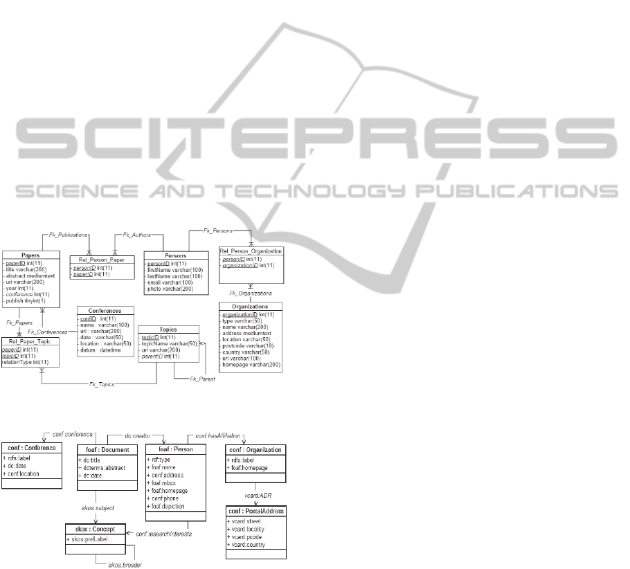
To illustrate the method, we will use the following
example. Figure 1 depicts the relational schema
ISWC_REL. Each table has a primary key, whose
name ends with ‘ID’. Persons and Papers represent
the main concepts. Rel_Person_Paper represents a
N:M relationship between Persons and Papers. The
labels of the arcs, such as FK_Publications, are the
names of the foreign keys. Figure 2 depicts the ontol-
ogy CONF_OWL, which reuses terms from FOAF
(Friend of a Friend), SKOS (Knowledge Organization
System), VCARD and DC (Dublin Core). The prefix
‘conf’ is used for the new terms defined in the
CONF_OWL ontology.
Figure 1: The ISWC_REL database schema.
Figure 2: The CONF_OWL ontology.
2.2 The R2RML Mapping by Assertion
Method (RBA)
The RBA method proposes to generate customized
R2RML mappings based on correspondence asser-
tions (Vidal et. al., 2014; Neto et. al., 2013). The in-
puts of the method are a relational database schema
that will be published as RDF and a set of domain on-
tologies. The output is an exported ontology, which
represents part of the relational data in RDF, the
R2RML mappings and a set of SQL view definitions.
The first step of RBA is manual and relies on the
user to define mappings between the relational data-
base and the domain ontologies using correspondence
assertions, which are much simpler to understand
than R2RML and yet suffice to capture most of the
subtleties of mapping relational schemas into RDF
schema (Vidal et. al., 2014). A tool has also been de-
veloped to the designer in this step (Vidal et. al.,
2014; Vidal et al., 2005)
Table 1 shows the abstract syntax and examples
of the three types of correspondence assertions.
Class correspondence assertions (CCAs) (as in
line 1 of Table 1) map tables into classes. Their ab-
stract syntax is
Ψ: C R[A
1
,...,A
n
]
where Ψ is the name of the CCA, C is a class of a
domain ontology, R[A
1
,...,A
n
] is a relation schema
with the attributes A
1
,...,A
n
(attributes of the primary
key of R) and
is an optional selection over R.
Object property correspondence assertions
(OCAs) (as in line 2 of Table 1) map tables into object
properties. Their abstract syntax is
Ψ: P
R /
where Ψ is the name of the OCA, P is an object prop-
erty of a domain ontology, R is a relation name of the
relational database schema and
is an optional path
from R. A path is a set of foreign keys that connect
relations in relational databases.
Datatype correspondence assertions (DCAs) (as
in line 3 of Table 1) map tables into datatype proper-
ties. Their abstract syntax is
Ψ: P
R /
/ {A
1
,...,A
m
}
where Ψ is the name of the DCA, P is a datatype
property of a domain ontology, R is a relation name
of the relational database schema,
is an optional
path from R and A
1
,...,A
n
are attributes of R.
The vocabulary of the exported ontology is simply
the set of classes and properties of the domain ontol-
ogies used in the correspondence assertions. Figure 3
shows the ISWC_RDF exported ontology generated
from the correspondence assertions that map the
ISWC_REL database schema of Figure 1 to the
CONF_OWL ontology of Figure 2.
The second step is automatic and compiles the
correspondence assertions into R2RML mappings
and SQL view definitions, as depicted in Figure 4.
ICEIS2015-17thInternationalConferenceonEnterpriseInformationSystems
6
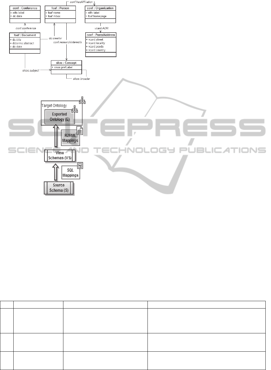
Figure 3: ISWC_RDF exported ontology schema.
Figure 4: Output of the design process.
2.3 The Design Rationale Model
R
2
BA uses the design rationale model detailed in
(Berardi et al., 2013). The basic concept of the model,
the DR graph, is composed of nodes that represent
reasoning elements, that is, elements that have been
traced, such as tables, classes, attributes. In each
node, the design rationale is represented using a ques-
tion whose answer is an idea. The questions record
the process that the reasoning element suffers and the
ideas represent what happened during this process.
For each kind of question, there is a controlled vocab-
ulary to express the ideas that answers it. The mecha-
nism to automatically answer the questions will be
explained in Sections 3 to 5.
The design rationale is incrementally recorded at
each step of R
2
BA by adding new reasoning elements
and by capturing the new questions and ideas of the
specific step. We will refer to each design rationale
generated by the number of the corresponding step
(Step1 generates DR1, etc.).
In terms of graphical representation, depending on
the step, nodes are represented as rectangles or circles
to facilitate understanding the graph. For instance, in
steps DR1 and DR5, nodes are indicated as rectangles
since they represent tables and attributes of the rela-
tional database; in the other steps, nodes are repre-
sented as circles and are related to ontology elements.
2.4 The Rationalizing R2RML
Mapping by Assertion Method
(R
2
BA)
R
2
BA is an extension of the RBA method to include
design rationale. It uses the correspondence assertions
to trace and record how the classes and properties are
created in RDF. R
2
BA extends RBA to capture the
design rationale, which is then used to enrich the ex-
ported ontology and to establish a link between simi-
lar classes and properties.
R
2
BA consists of 6 steps, divided into 3 groups
according to their goals. Each one of these groups is
discussed in detail in Sections 3 to 5.
The first group comprehends two steps: “Step 1:
Creation of the correspondence assertions” and “Step
2: Creation of an exported ontology to represent rela-
tional data in RDF”. This group receives as input a
relational schema, the data source schema, and sev-
eral target ontologies of the user’s choice, where each
ontology is composed by a vocabulary and set of con-
straints. As output, it produces an exported ontology
Table 1: DR interpretation for Class, Object Property and Data type property Correspondence Assertions.
Type Definition DR interpretation Examples of Correspondences Assertions
CCA
Ψ: C
R[A
1
,...,A
n
]
(
is optional)
Class type Table[URI] FILTER
(FILTER is omitted if so is
)
1:
foaf:Person ≡ Persons[personID]
2:
skos:Concept ≡ Topics[topicID]
3:
foaf : Document ≡ papers [PaperID],
FILTER [papers.Year > 2002]
OCA
Ψ: P
R /
(
is optional)
ObjP mapped Table_Domain /
Ref_Att_URI_Range
(Ref_Att_URI_Range is optional)
4
: conf:researchInterests
Persons /
[Fk_Authors, Fk_Publications, Fk_Papers, Fk_Topics ]
DCA
Ψ: P
R /
/ {A
1
,...,A
m
}
(
is optional)
DataP mapped Table_Domain /
Ref_Att_Range / {Att_Lit_Range
n
}
(Ref_Att_Range is optional)
5:
foaf:name
Persons / {firstName, lastName}
R2BA-RationalizingR2RMLMappingbyAssertion
7

and the design rationale DR1 of Step 1 and DR2 of
Step 2.
The second group enriches the exported ontology
to facilitate interoperability. It also comprehends two
steps: “Step 3: Generating annotations” and “Step 4:
Generating linking recommendations”. This group re-
ceives as input the exported ontology and DR2. As
output, it produces an enriched exported ontology and
the corresponding design rationale (DR3 for Step 3
and DR4 for Step 4).
The last group generates SQL views according to
the enriched exported ontology and the R2RML map-
pings. It comprehends two steps: “Step 5: Generating
SQL views” and “Step 6: Generating R2RML map-
pings”. This group receives as input the enriched ex-
ported ontology and DR4. As output, it produces: a
set of relational views schemas; a set of R2RML map-
pings; and the final DR (DR5 for Step 5 and DR6 for
Step 6.
3 GROUP 1 - CREATING THE
MAPPINGS AND THE
EXPORTED ONTOLOGY
3.1 Overview
The first group of steps of R
2
BA creates the corre-
spondence assertions and an exported ontology to
represent relational data in RDF.
Step 1 – Generating Correspondence Assertions.
This step consists in a manual specification of a set of
correspondence assertions between elements of the
database relational schema and terms from vocabular-
ies of user’s choice. The design rationale captured in
this step, referred to as DR1, records the original for-
mat of the data source schema elements and tracks
which elements are not mapped.
To visualize the DR1 captured in this step, con-
sider the ISWC_REL schema depicted in Figure 1.
Observe the table Persons and its attributes first-
Name, lastName, email and photo. Their original for-
mats are represented at DR1 in Figure 5 through the
rectangular nodes with the same names.
The questions associated with DR1 are Element
and Map. The Element question seeks to explicit the
original format of the element, so it may be answered
with relational database elements, such as Table, Att,
KeyAtt or FKAtt for table, attribute, primary key at-
tribute and foreign key attribute, respectively. For ex-
ample the rectangular node Persons has the answer
Table and the rectangular nodes firstName and last-
Name have Att. To represent a relationship between
two tables, DR1 answers the question Element with
FKAtt and creates a question Ref to be answered with
the names of the table and attribute that is the refer-
ence of the FKAtt.
To record elements that are not mapped, R
2
BA
has a mechanism to compare the elements present in
the correspondence assertions and the elements pre-
sent in the original database schema. For example, at-
tribute photo of table Persons has the question Map
answered with NOT. At DR1, this is the only case
where the question Map is asked.
Step 2 – Generating the Exported Ontology.
This step consists in using the set of correspondence
assertions to automatically generate the exported on-
tology. According to the RBA method, the list of cor-
respondence assertions is consumed to generate the
exported ontology, in the following order: all Class
Correspondence Asserions are first mapped to the ex-
ported ontology; then all Object Correspondence As-
sertions; and finally all Data type Correspondence
Assertions. The design rationale captured in this step,
referred to as DR2, records information parallel to
each mapping created.
Together, DR1 and DR2 allow answering the fol-
lowing questions: (i) What is the original form of the
data in the data source schema?; (ii) Are all elements
in the data source schema mapped? If not, which
were and which were not mapped?; (iii) For those el-
ements that were mapped, how they were mapped as
ontology elements?
In order to trace how the elements were mapped
and record this information at DR2, we developed a
DR interpretation for each kind of CA, as shown in
Table 1. Each interpretation expression is used to an-
swer the questions asked during this step.
The next sections detail and exemplify how to
generate the DR2 for Class Correspondence Asser-
tion, Object Correspondence Assertion and Data type
Correspondence Assertion.
3.2 Design Rationale for Class
Correspondence Assertion
Consider a class correspondence assertion (CCA) of
the form Ψ: C R[A
1
,...,A
n
], that is, which does not
use a filter (the first two examples in line 1 of Table
1). The DR interpretation for such CCAs is formal-
ized as the expression “Class type Table[URI]”, read
as “a class that is mapped as type (rdf:type) from a
table represented by R using attributes A
1
,...,A
n
to
build the URIs”. For example, the assertion in the first
line of Table 1
Ψ
1
: foaf:Person ≡ Persons[personID]
ICEIS2015-17thInternationalConferenceonEnterpriseInformationSystems
8
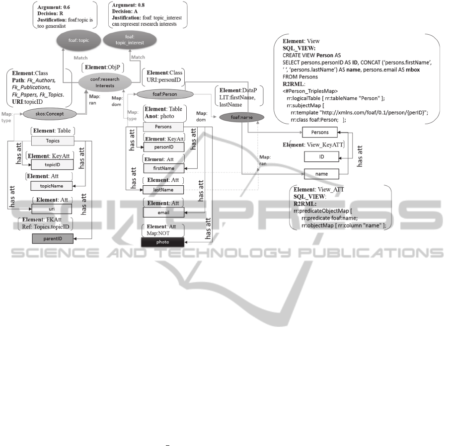
Figure 5: DR graph for the motivating example.
maps table Persons (see Figure 1) to class foaf:Per-
son (see Figure 2) using attribute personID to build
the URI of the class. The DR for this assertion there-
fore has Class as foaf:Person, Table as Persons and
URI as the attribute personID. Figure 5 shows the rep-
resentation of this example.
DR2 increments DR1 by adding a new circle node
for Class, called foaf:Person, and connecting it to the
corresponding node of Table, that is, the table
Persons. The questions for the new node Class
are Element, URI and Map. To answer the question
Element, the Class component of the DR interpreta-
tion expression is used. To answer the URI question,
the instantiation of the component URI
of the DR in-
terpretation expression is used (personID in the ex-
ample). Finally, the question Map is related to the
connection arrow between the correspondent nodes
Class and Table. To answer it, the component type
of
the DR interpretation expression is used.
Consider now a class correspondence assertion of
the form Ψ: C R[A
1
,...,A
n
]
, that is, which uses a
filter
(the third example in line 1 of Table 1). Such
assertions are represented in DR2 with the help of the
question FILTER, answered by recording the filter
used in the correspondence assertion (not shown in
Figure 5 due to space limitation).
3.3 Design Rationale for Object
Correspondence Assertion
After recording the design rationale model for the
class correspondence assertions, DR2 represents the
design rationale for object property correspondence
assertions (OCAs).
Consider an OCA of the form Ψ: P
R /
(as in
line 2 of Table 1). The DR interpretation of an OCA
is formalized as the expression “ObjP mapped Ta-
ble_Domain / Ref_Att_URI_Range”, read as “an ob-
ject property P is mapped using a Table R as its do-
main and its range is represented by an URI com-
posed by a key attribute of a table, that is found by
following the path
in Ref_Att_URI_Range”.
For example, the OCA in line 2 of Table 1
OCA: conf:researchInterests
Persons /
[Fk_Authors, Fk_Publications, Fk_Papers, Fk_Top-
ics]
maps the object property conf:researchInterests (in
Figure 2) using the table Persons (in Figure 1) to rep-
resent the domain and the concept skos:Concept is
found by following the path [Fk_Authors, Fk_Publi-
cations, Fk_Papers, Fk_Topics] (Figure 1 and Figure
2). The DR for this assertion therefore has ObjP as
conf:researchInterests, Table_Domain as Persons
and Ref_Att_URI_Range as Fk_Authors, Fk_Publica-
tions, Fk_Papers, Fk_Topics. Figure 5 shows the rep-
resentation of this example. DR2 increments DR1 by
R2BA-RationalizingR2RMLMappingbyAssertion
9

adding a new circle node for ObjP called conf:re-
searchInterests. The questions for the new node ObjP
are Element and Map. To answer the question Ele-
ment, the ObjP
component of the DR interpretation
expression is used. As ObjP is an object property, the
domain and range are URIs. When the range is an
URI composed by following a path in the correspond-
ence assertion, DR2 records a question Path and an-
swers it with the path
provided by the correspond-
ence assertions. Figure 5 shows this example for the
range of the object property conf:researchInterest.
The question URI is answered by the ID attribute used
to compose the URI, which may be found by follow-
ing a path in the correspondence assertion. To identify
the arrows that are related to domain and range map-
pings, the DR model uses the question Map and the
answers dom and ran for domain and range, respec-
tively. Thus, the connection between the domain and
range should be directed from the ontology element
corresponding to the URIs. It is important to highlight
that the OCA uses a table to represent the domain of
the ObjP, but the true domain is the ontology element
corresponding to this table (and likewise for the range
representation).
For example, in the OCA of Table 1, the ObjP
node is connected to the node labeled foaf:Person,
which is the ontology element mapped from the table
Person. The same happens with the connection be-
tween the ObjP node and its range. In the DR2 graph,
a double arrow indicates a range defined by a path,
while a single arrow indicates a range defined by a
single attribute.
3.4 DR for Data Type Correspondence
Assertion (DCA)
After having recorded the DR2 for CCAs and OCAs,
finally the DR for DCAs is recorded.
Consider
first a DCA of the form Ψ: P
R /
{A
1
,...,A
m
} (as in line 3 of Table 1), that is, which does
not use a path. The DR interpretation of this corre-
spondence assertion is formalized as the expression
“DataP mapped Table_Domain/ {Att_Lit_Range
n
}”,
read as “a datatype property P is mapped using table
R as its domain and its range is a set of values gener-
ated using attributes {A
1
,...,A
m
}”. Using this interpre-
tation for the example in Table 1
DCA:foaf:name
Persons / {firstName, lastName},
DataP is foaf:name, Table_Domain is Persons and
{Att_Lit_Range
n
} is firstName,lastName. This DCA
maps the datatype property foaf:name (Figure 2) us-
ing the table Persons (Figure 1) as domain and the
values of the attributes firstName and lastName (Fi-
gure 1) as range.
The representation of this example is shown in
Figure 5 and is similar to the DR of an object prop-
erty. The most important difference is that, in
datatype properties, the range is not a class, but a
XML data type defining a set of literals. So, the liter-
als are generated from attribute values, as indicated in
the DCA. Thus, the connection in the DR graph is di-
rected from the attributes. As this example uses a
composition of two attributes, both are connected to
the node represented by dashed lines. When the DCA
specifies only one attribute, a single line is used.
For
a DCA of the form Ψ: P
R /
/ {A
1
,...,A
m
},
which uses a path, the DR follows likewise. Similarly
to OCAs that uses a path to find ranges, a question
Path_ran is created in the node associated with the
data type property and answered with the path in the
correspondence assertion. In this case, a double arrow
in the DR graph indicates a range found by following
a path in the correspondence assertion.
Table 2: Step 5 and 6 for classes.
4 GROUP 2 – ENRICHING THE
EXPORTED ONTOLOGY
This group of steps enriches the exported ontology to
facilitate interoperability.
Step 3 – Generating annotations. This step consists
in generating annotations for those cases where the
relational database is composed of a private parte
(that is not published as RDF) and a public part (that
is published). This is a new step in the RBA approach
and aims at adding information about the private re-
lational schema in the exported ontology.
DR3 increments the nodes in DR2 with annota-
tions, according to a neighboring mapping, defined
as: for each mapped element, look for a neighbor in
the DR graph that has the question Map answered
with NOT, which means it was not mapped to the ex-
Operation 1: For each class C in V
E
where K
1
,...,K
n
are the
datatype properties of the key of C do
1.1 Create a relational view also named C;
Create a new node that is an Element:View in DR4
Connect the Element View to the node correspondent to the
class C
1.2 Create K
1
, … , K
n
, the attributes of the primary key of view
C;
Create a new node that is an Element:View_ Key_Att in DR 4
Connect the new Key_Att Element to the View Element
correspondent and label it with “has_att”
1.3 Create the subject map referring to view C using template
T1.
In the Element View node, create a question “R2RML” and
answer it with the tri
p
le ma
p
created in subste
p
1.3.
ICEIS2015-17thInternationalConferenceonEnterpriseInformationSystems
10

ported ontology. If one such node exists, a new ques-
tion is created Anot at the node that found an element
that was not mapped. The question Anot is answered
with the name of the unmapped node. This infor-
mation is added to the exported ontology as a datatype
property rdfs:comment whose value is a literal com-
posed of the names of the unmapped nodes.
The search for unmapped neighbors follows an
annotation strategy up to a certain depth in the DR
graph. As an initial strategy and based on empirical
observations, we considered a maximum of two lev-
els. More specifically, we noticed that, for automatic
annotations, including more than two levels becomes
superfluous, as the additional levels are more likely to
be out of context (Berardi et al., 2014). For instance,
observe in Figure 5 that the attribute photo is marked
with the question Map:NOT and is therefore anno-
tated with the mapped node Persons.
The benefits of using the DR graph to generate an-
notations, instead of directly using the relational da-
tabase, are: (i) Since the DR graph is created for prov-
enance purposes, it can be accessed without having to
create a new graph based on the relational schema to
know what has to be annotated; (ii) Since the DR
graph is created in all steps of R
2
BA, it can be con-
sumed whenever it is needed, without having to rerun
the steps from the very beginning.
Step 4 – Generating linking recommendations.
This step consists in executing ontology matching al-
gorithms using as input the annotated exported ontol-
ogy . The annotation helps ontology matching tech-
niques to keep the context of the elements in the ex-
ported ontology. When only part of the schema is
published, this part can lose information that can be
useful for Ontology Matching algorithms.
In order to promote interoperability, we seek to
establish a link between similar classes or properties
using rdfs:equivalentClass or rdfs: equivalentProp-
erty properties. In this step the user interaction plays
an essential role because the OM process gives a list
of recommendations for the terms of the exported on-
tology. Ideally, the user should know the database do-
main so that he or she can accept or reject the recom-
mendations. These links of the annotated exported
ontology are part of the enriched exported ontology.
DR4 increments DR3 with two new nodes for the
two largest recommendation similarity values. Then,
the questions involved at this step are: Argument, an-
swered with the similarity value output by the OM al-
gorithms; Decision, with A or R, which represents the
domain expert decision for accepting or rejecting the
recommendation, respectively; and Justification, with
the justification provided by the domain expert about
her or his decision.
Table 3: Step 5 and 6 for object properties.
For instance, in Figure 5, the object property conf:re-
searchInterests receives two recommendations for
terms that seem to be equivalent to foaf:topic and
foaf:topic_interest. The corresponding nodes of the
recommendations are connected to the node of the
term conf:researchInterests. This connection is la-
beled with Match to explicit that they are recommen-
dations from the Ontology Matching techniques.
Together, DR3 and DR4 allow answering the follow-
ing questions: (i) Which elements received annota-
tions and what are the annotations?”; (ii) Which rec-
ommendations each term received from the OM tech-
niques? (iii) Which recommendations were accepted
and why? (iv) Which recommendations were rejected
and why?
5 GROUP 3 – GENERATING SQL
VIEWS AND R2RML
MAPPINGS
The last group of steps generates SQL views accord-
ing to the enriched exported ontology and the
R2RML mappings.
Step 5 – Generating SQL views.
Operation 3: For each object property P in V
E
do
Let D and R be the views that match to the domain and range
of P, respectively, let K
D1
,...,K
Dn
be the attributes of the
primary key of D and let K
R1
,...,K
Rn
be the attributes of the
primary key of R; // views D and R were created in Step 1
Case 3.2: P has cardinality greater than 1.
3.2.1. Create relational view D_P;
Create a new node Element View
Connect the new node Element View to the Element ObjP node
correspondent
3.2.2. Create attributes K
D1
,...,K
Dn
in D_P whose types are de-
fined as in D;
Create a new node Element View_FK_PK
Connect the new node Element View_FK_PK to the Element
View correspondent and label the connection with “has_att”
3.2.3. Create foreign key FK_D_P_D(D_P:{K
D1
,...,K
Dn
},
D:{K
D1
,...,K
Dn
});
Create the question “Ref” in the node Element View_FK_PK
and answer it with D:{K
D1
,...,K
Dn
}
3.2.4. Create attributes K
R1
,…, K
Rn
in D_P whose types are
defined as in R;
Create a new node Element View_FK_PK
Connect the new node Element View_FK_PK to the Element
View node correspondent
3.2.5. Create foreign key FK_D_P_R(D_P:{K
R1
,…, K
Rn
},
R:{K
R1
,…, K
Rn
});
Create the question Ref and answer it with D:{KD1,...,KDn })
3.2.6. Create the subject map referring to view D_P and
predicate object map for P using template T5.
Create the question “R2RML” in the Element View node
and answer it with the result of the step 3..2.6
R2BA-RationalizingR2RMLMappingbyAssertion
11

This step consists in automatically generating a set of
relational view schemas that is a direct transformation
of the enriched exported ontology. In (Neto et. al.,
2013) an algorithm is presented to automatically gen-
erate the view schemas based on the exported ontol-
ogy and the correspondence assertions.
Step 6 – Generating R2RML mappings.
This step consists in automatically generating
R2RML mappings from the views to the enriched ex-
ported ontology, which is one-to-one. The DR5 and
the final DR6 are captured in parallel and they allow
to answer the following questions: (i) “Which SQL
view is associated with each element of the enriched
exported ontology?”; (ii) “Which R2RML mapping
refers to each element of the enriched exported ontol-
ogy?”. The final DR6 makes it possible to trace all the
transformations that each element in the original rela-
tional schema suffered during the mapping process.
The algorithm that automatically generates the
view schemas and the R2RML mappings has 3 main
steps. Each one of these steps implements the SQL
view and the R2RML mappings generation, respect-
ing this order: classes first, then datatype properties
and, finally, object properties. Tables 2 and 3 show
the steps for classes and object properties mappings
and DR composition respectively. Due to space limi-
tations, we do not explore the operations for datatype
properties.
The algorithm receives as input the enriched ex-
ported ontology and a set of templates for creating
SQL views and R2RML mappings. The complete list
of these templates can be found in (Vidal et. al.,
2014).
Let V
eEO
be the vocabulary of the enriched ex-
ported ontology and K
1
,…,K
n
be the attributes of a
view C. Table 2 shows the first part of the algorithm
related to the class mapping. As an example of Step
1, consider the class foaf:Person of the exported on-
tology in Figure 3. Step 1 creates a view for this class
called Persons, then DR5 generates a new rectangular
node, also called Person, as shown in Figure 5.
At DR5, the questions involved are Element and
SQL_VIEW. As DR5 is coupled with the view crea-
tion step, the algorithm is able to answer the question
Element with View.
After having created the view, the algorithm also
creates the ID attribute; DR4 then generates a new
rectangular node. In this case, the question Element is
answered with View_KeyATT. The question
SQL_VIEW is answered as the view is in fact created.
The new node Persons in DR5 represents the view
Persons, which corresponds to the class foaf:Person
in DR2, that consequently represents the Table Per-
sons in DR1.
Following Step 1 of the algorithm, the last sub
step is to generate the R2RML mapping. For that, the
algorithm uses a list of templates according to each
step. Space limitations do not permit to explore each
template used, so we cover only one as an example.
For the class R2RML mapping, template T1 is
used:
T1: <#C_TriplesMap>
rr:logicalTable [rr:tableName “C”];
rr:subjectMap [
rr:template “namespaceOfC/{K
1
}/{K
2
}/…/{K
n
}/…/”;
rr:class C; ];
DR5 is incremented with the template information
recording, so that DR6 is built. The last sub step of
Operation 1 is to finish DR6 with the question
R2RML in the Element:View node and answering it
with the instantiation of the template T1 used.
<#Person_TriplesMap>
rr:logicalTable [rr:tableName “Person”];
rr:subjectMap [
rr:template “http://xmlns.com/foaf/0.1/person/{personID}”;
rr:class foaf:Person; ];
Finally, Table 3 shows the part of the algorithm
related to the object property mappings. Similarly to
the datatype property mappings, this part of the algo-
rithm implements different strategies for object prop-
erties with cardinality equal to 1 (Case 3.1) or greater
than 1 (Case 3.2). In our example, we explore Case
3.2 using as example the object property conf:re-
searchInterests of the exported ontology in Figure 3.
In Step 3, a new view is created, called Per-
son_ResearchInterests, with two ID attributes
ID_Person and ID_Concept. Both are also foreign
keys to construct the domain and range of the object
property. The DR 5 related with this step is the crea-
tion of a new node, called Person_ResearchInterest,
that is a view element, with two new nodes, ID_Per-
son and ID_Concept, which are primary keys and for-
eign keys, represented as View_FK_PK, to answer the
question Element.
Following Step 3 (Case 3.2), the next sub step is
to generate the R2RML mapping. In this case, the tri-
ple map for object property mapping is created using
template T5:
T5: <#D_P_TriplesMap>
rr:logicalTable [ rr:tableName "D_P " ];
rr:subjectMap [
rr:template "namespaceOfD/{K
D1
}/{K
D2
}/... /{K
Dn
}/";
rr:class D; ];
rr:predicateObjectMap [
rr:predicate P;
rr:objectMap [
rr:parentTriplesMap <R_TriplesMap>;
rr:joinCondition [
rr:child “K
R1
”;
rr:parent “K
R1
”; ];
…
rr:joinCondition [
ICEIS2015-17thInternationalConferenceonEnterpriseInformationSystems
12

rr:child “K
Rn
”;
rr:parent “K
Rn
”; ]; ]; ];
The composition of DR6 is created by answering
the question R2RML at the rectangular node Per-
son_ResearchInterests with the help of template T5:
T5: <#Person_ResearchInterests_TriplesMap>
rr:logicalTable [rr:tableName “Person_ResearchInterests”];
rr:subjectMap [
rr:template "http://xmlns.com/foaf/0.1/person/{personID}";
rr:class foaf:Person; ];
rr:predicateObjectMap [
rr:predicate conf:researchInterests;
rr:objectMap [
rr:parentTriplesMap <Concept_TriplesMap>;
rr:joinCondition [
rr:child “topicID”;
rr:parent “topicID”; ]; ]; ] .
6 RELATED WORK
Typically, tools developed to support the customized
mapping approach, such as Triplify (Auer et. al.,
2009), D2R Server (Bizer and Cyganiak, 2006) and
OpenLink Virtuoso (2006), do not address design ra-
tionale issues.
The notion of correspondence assertions was in-
troduced in (Vidal et. al., 2005) to define mappings
between instances of source schema to instances of
XML view schema. The RBA tool was developed to
simplify the generation of R2RML mapping and to
help the publication of relational database by using
correspondence assertions (Neto et. al., 2013). The
RBA tool and, in fact, none of previous work on cor-
respondence assertions (Vidal et al., 2014; Pequeno
et al., 2014) considered design rationale questions.
In previous work (Berardi et al., 2013) we devel-
oped a method to capture design rationale for direct
mapping processes.
R
2
BA, introduced in this paper, extends the RBA
tool to collect design rationale and to use it to find
links to similar terms in known domain ontologies. It
is the first method to capture design rationale for a
customized mapping process as far as we know.
7 CONCLUSIONS
To improve the transparency of customized mappings
using R2RML, we proposed to couple design ra-
tionale with correspondence assertions. With the help
of a motivating example, we discussed how to repre-
sent this design rationale and how it can help answer
questions regarding the awareness of the possible
transformations that the published data suffered. By
consuming the final design rationale captured, it is
possible to observe the transformation of the data
from their original format in the database, until their
final format as an exported ontology, SQL views and
R2RML mappings.
We discussed how to use design rationale for
transparency and maintenance purposes. We also ar-
gued that design rationale may help address interop-
erability issues by creating an enriched exported on-
tology. The design rationale captured may help new
users use R2RML mappings by observing how the
mapping process of the original data was imple-
mented. He or she can learn different situations where
R2RML is used in a convenient way.
As for future work, we plan to extend the method
proposed in this paper to capture the design rationale
of complex correspondence assertions (Pequeno et.
al., 2014). We also plan to simplify the design ra-
tionale model, in this specific case, by making it
closer to the syntax of the complex correspondence
assertions.
REFERENCES
Auer, S., Dietzold, S., Lehmann, J., Hellmann, S., and Au-
mueller, D.: Triplify - Lightweight Linked Data Publi-
cation from Relational Databases. Proc. 18th Int’l.
Conf. on World Wide Web (WWW 2009), pp. 621-630.
Bizer, C., and Cyganiak, R.: D2R Server – Publishing Re-
lational Databases on the Semantic Web. Proc. 5th Int’l.
Semantic Web Conf. (ISWC 2006).
Das, S., Sundara, S., and Cyganiak, R.: R2RML: RDB to
RDF Mapping Language, W3C Working Draft,
http://www.w3.org/TR/r2rml/ (2012).
Sequeda, J., Tirmizi, S., Corcho, O., Miranker, D.: Survey
of directly mapping SQL databases to the Semantic
Web (2011). Knowledge Engineering Review, 26, pp.
445-486.
Vidal, V., Casanova, M., Monteiro, J., Neto, L. A Semi-
Automatic Approach for Generating Customized
R2RML Mappings. In proceedings of 29th Symposium
On Applied Computing, Gyeongju, Korea, March,
2014.
Vidal, V. M., Araujo, V. S., Casanova, M. A.: Towards Au-
tomatic Generation of Rules for Incremental Mainte-
nance of XML Views of Relational Data. Proc. Web
Information Systems Engineering (WISE 2005), pp.
189-202.
Berardi, R., Breitman, K.K., Casanova, M.A., Lopes, G.R.,
Medeiros, A.P.: StdTrip+K: Design Rationale in the
RDB-to-RDF process. Proc. 24th International Confer-
ence on Database and Expert Systems Applications
(Aug. 26–29, 2013), Prague, Czech Republic. Database
and Expert Systems Applications. Lecture Notes in
Computer Science, Vol. 8055, 2013.
Neto, L., Vidal, V., Casanova, M., Monteiro J.: R2RML by
Assertion: A Semi-Automatic Tool for Generating.
R2BA-RationalizingR2RMLMappingbyAssertion
13

Customized R2RML Mappings. ESWC 2013.
Berardi, R., Schiessl, M., Thimm, M., Casanova, M.A. The
Role of Design Rationale in the Ontology Matching
Step during the Triplification of Relational Databases.
Proc. 25th International Conference on Database and
Expert Systems Applications, Munich, Germany (Sept.
1-5, 2014).
Pequeno, V.M., Vidal, V.M.P., Casanova, M.A., Neto,
L.F.T., Galhardas, H. Specifying Complex Correspond-
ences between Relational Schemas and RDF models for
generating customized R2RML mappings. Proc. 18th
International Database Engineering & Applications
Symposium, Porto, Portugal (July 7-9, 2014), pp. 96-
104.
ICEIS2015-17thInternationalConferenceonEnterpriseInformationSystems
14
