
Support of Scenario Creation by Generating Event Lists from
Conceptual Models
Kenta Goto
1
, Shinpei Ogata
2
, Junko Shirogane
3
, Takako Nakatani
4
and Yoshiaki Fukazawa
1
1
Department of Computer Science and Engineering, Waseda University, 3-4-1 Okubo Shinjuku-ku, Tokyo, Japan
2
Graduate School of Science and Technology, Shinshu University, 4-17-1 Wakasato Nagano-shi, Nagano, Japan
3
Department of Communication, Tokyo Woman’s Christian University, 2-6-1 Zenpukuji Suginami-ku, Tokyo, Japan
4
Graduate School of Systems Management, University of Tsukuba, 3-29-1 Otsuka Bunkyo, Tokyo, Japan
Keywords: Conceptual Model, Scenario, Requirements Definition, Use Case.
Abstract: In the requirements definition phase, conceptual models are used to understand the developing software.
Although scenarios are often described on the basis of conceptual models, there are cases that necessary
requirements are omitted in the scenarios when the scenarios are created manually. Herein we propose an
approach to support scenario creation from conceptual models where event lists of scenarios, which include
checkpoints to define requirements, are generated from conceptual models automatically. The conceptual
models represent the core resources of the software, the owner of the core resources, and use cases as class
diagrams. Then software engineers and their clients arrange the event lists and define requirements as
scenarios on the basis of the checkpoints. Our approach can support describing scenarios with all the
necessary requirements from conceptual models. To confirm the effectiveness of our approach, we
compared our approach to the all-manual approach.
1 INTRODUCTION
To understand the software domain, software
engineers create conceptual models very early in the
requirements definition phase according to the
client’s requirements. Conceptual models are the
basis for other models in the late development phase.
On the other hand, in the requirements definition
phase, operation flows are frequently described as
scenarios written in a natural language. Scenarios
represent interaction flows between users and the
target software.
Creating scenarios can be troublesome because
necessary requirements are often omitted when
scenarios are created manually on the basis of
conceptual models. These omissions occur because
the scenarios are often narrowed using only software
engineers’ intention. Thus, describing scenarios on
the basis of conceptual models depends on the skills
and experience of the software engineers. If the
requirements definitions are insufficient, software
projects tend to fail (Clancy, 1995). Recently, some
works have examined activities to help improve the
quality of scenarios as requirements (Alspaugh and
Antón, 2008) (Robertson and Robertson, 2012).
To address this problem, we propose an approach
that supports creating scenarios from conceptual
models by allowing software engineers to describe
scenarios with all necessary requirements on the
basis of conceptual models. Concretely, software
engineers initially describe a conceptual model using
our template. Then Use Case Correspondence
Models (UCCMs) are generated by dividing the
conceptual models. Next event lists of scenarios are
generated from the UCCMs. Each generated event
includes a flag that represents a checkpoint to define
requirements. Checkpoints indicate that internal
processing of the target software may need to be
defined. Finally software engineers and clients
arrange the event lists and define requirements on
the basis of the flags. Through this process,
scenarios are created with all the necessary
requirements.
2 BASIC CONCEPTS
2.1 Conceptual Models
Conceptual models represent the target software
376
Goto K., Ogata S., Shirogane J., Nakatani T. and Fukazawa Y..
Support of Scenario Creation by Generating Event Lists from Conceptual Models.
DOI: 10.5220/0005327803760383
In Proceedings of the 3rd International Conference on Model-Driven Engineering and Software Development (MODELSWARD-2015), pages 376-383
ISBN: 978-989-758-083-3
Copyright
c
2015 SCITEPRESS (Science and Technology Publications, Lda.)

domain using the relations between each object
(Olivé, 2007). Typically the conceptual models are
created at the beginning of the requirements
definition phase. Moreover, conceptual models are
often used as the basis for various models.
Conceptual models can be represented as class
diagrams in UML (Unified Modeling Language).
In our approach, conceptual models are created
along with the conceptual model template that we
define based on the knowledge level in the Analysis
Patterns (Fowler, 1997). Figure 1 shows our
conceptual model template, which has three classes:
object, owner, and operation classes. The object
class represents a core resource in the target
software. The owner class represents the owner of
the object class. The operation class indicates
operations to the core resource. The operation class
contains sub-classes that represent use cases to
operate the core resource. We consider that system
just composes of a core resource in software, an
owner of the resource and operations for the
resource, so the template consists of the three
classes. However, we limit the number of the
resource to one. In the case that there are some
resources in software, it can be possible to express
the case by creating some conceptual models on the
basis of the template.
Figure 2 shows an example of a conceptual
model for a banking system created on the basis of
our conceptual model template. The Customer, the
Bank Account and the Bank Service class
correspond to each class such as the owner, the
object and the operation class in the template. The
Customer has a Bank Account, which is a core
resource of the banking system. The Bank Service is
to access the Bank Account. In this conceptual
model, the system has four use cases: withdrawal,
balance inquiry, transfer, and deposit.
2.2 Scenarios
Operation flows of software are often written by
scenarios, which are text-based narratives that
indicate how a user operates software and how the
software should behave.
On the other hand, a sentence in scenarios is
called an event. A use case has a pre-condition,
which a user must satisfy at the beginning of a
scenario, and a post-condition, which a user must
satisfy upon completing a scenario (Cockburn,
2000).
Figure 1: Conceptual model template.
Figure 2: Conceptual model of a banking system.
2.3 Use Case Correspondence Models
Generating scenarios from only conceptual models
automatically is difficult because the conceptual
models don’t express use cases such as scenarios. It
needs to transform the conceptual models into the
form of use cases for generating scenarios
automatically or semi-automatically. Therefore, to
generate scenarios from conceptual models in our
approach, the conceptual models are divided into
Use Case Correspondence Models (UCCMs). The
UCCMs are the models we defined, they express
structure of use cases such as subjects, objects and
predicates in scenarios. Each UCCM corresponds to
one use case. UCCMs include necessary items for
scenarios such as:
・ Identification of an actor in use cases
・ Attributes used in each use case
・ Classifications of the input and/or output item
・ Pre-condition/post-condition
These items express who, for which use case, for
which attribute, and what to do in a scenario. Due to
UCCMs, these items can be clarified.
UCCMs are expressed as class diagrams in UML
and are created on the basis of conceptual models.
We define the UCCM template based on the
knowledge level in the Analysis Pattern (Fowler,
1997). Figure 3 shows our UCCM template, which
is composed of three classes: object, operation, and
actor classes. The object class has the same meaning
as the one in the conceptual model template. The
actor class indicates the actor in the use case. We
regard the owner of the core resource in the target
software as the actor in use cases, so the owner class
is specified as the actor class. In the case that the
owner is not to be the actor, generated scenarios
from the UCCMs can be deleted by the judgment of
software engineers and clients. The operation class
is a subclass in conceptual models. Thus, one
UCCM is generated for every subclass of the
operation class in the conceptual models.
SupportofScenarioCreationbyGeneratingEventListsfromConceptualModels
377
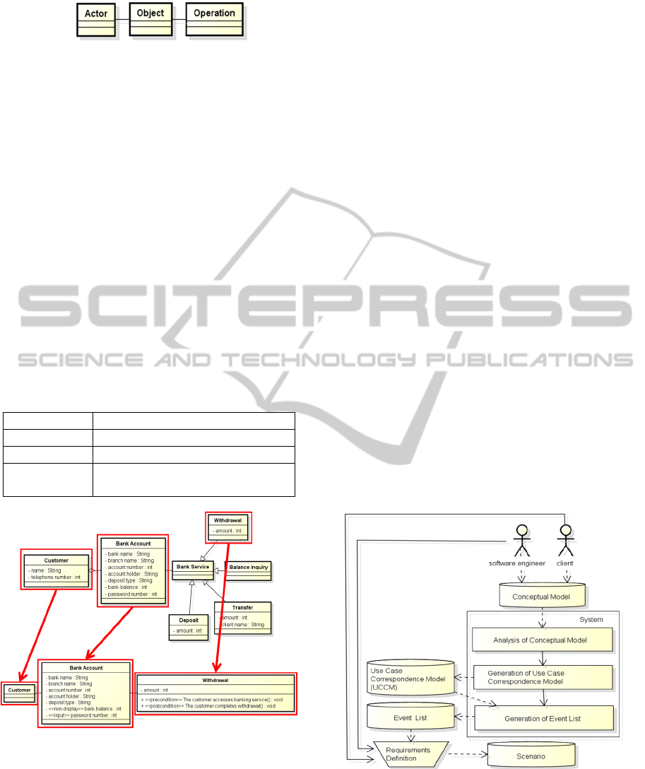
Figure 3: UCCM template.
The attributes of each UCCM class are used in
each use case. Software engineers can delete
unnecessary attributes. Additionally, software
engineers can add pre- and post-conditions to the
operation class and stereotypes to represent the
attribute types such as input only, output only, and
non-display. Table 1 shows a list of the stereotypes
used in our approach.
Figure 4 shows an example of the
correspondence between the UCCM and the
conceptual model. The top diagram is the conceptual
model and the bottom diagram is the UCCM. Both
models express the use case of withdrawal in the
banking system shown in Fig. 2. Each class in the
conceptual model corresponds to the class with the
same name in the UCCM. Similarly, the UCCMs of
the use cases for balance inquiry, the transfer, and
the deposit are created.
Table 1: List of stereotypes.
Stereotype Meaning
Input Only input item
Output Only output item
Non-display Not shown item used in the
internal processing of the system
Figure 4: Correspondence between the UCCM and the
conceptual model.
3 FEATURES
Reduction of Missing Necessary Events
The generated event lists include flags to verify
whether internal processing is required. Software
engineers extract the requirements for internal
processing from clients based on the flags. If there
are no requirements for a flag, only the flag is
detected. However, it is important to confirm the
necessity of each flag to reduce the number of
missing requirements.
Provision of a Strategy to Create Scenarios from
Conceptual Models
Conceptual models and scenarios are often described
independently in software development. Creating
conceptual models and scenarios independently may
lead to inconsistencies between models. Hence, a
strategy to create scenarios from conceptual models
is necessary. In our approach, event lists of scenarios
are generated from conceptual models automatically
through generating UCCMs by our system. Then
software engineers and clients create scenarios on
the basis of the generated event lists. In this way,
scenarios are directly created from conceptual
models.
Support to Understand Attributes used in each
Event
It is difficult to see attributes necessary in a use case.
By UCCMs, software engineers can easily see the
attributes in each use case because UCCMs simply
express structure of use cases.
4 APPROACH
Figure 5: Flow of our approach.
Our approach aims to support scenario creation from
conceptual models. Figure 5 shows the flow of our
approach, which consists of four phases.
1. Analysis of the Conceptual Model
MODELSWARD2015-3rdInternationalConferenceonModel-DrivenEngineeringandSoftwareDevelopment
378
2. Generation of the Use Case Correspondence
Model
3. Generation of Event Lists
4. Requirements Definition
4.1 Analysis of Conceptual Models
Initially the conceptual model is represented as a
class diagram by UML modeling tool astah* (astah,
2014) and is created on the basis of our conceptual
model template described in section 2.1. Then our
system analyzes the conceptual model and extracts
class names, attributes of each class, and subclasses
of the operation class.
4.2 Generation of UCCMs
After analyzing the conceptual model, our system
generates UCCMs automatically. First, the owner
class is copied as the actor class. The object class of
the conceptual model is copied to the UCCM. Then
the subclass of the operation class in the conceptual
model is copied to the UCCM. Next our system adds
methods as pre- and post-conditions. These methods
have stereotypes of <<pre-condition>> and <<post-
condition>>.
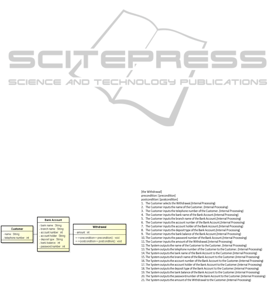
For example, from the conceptual model of the
banking system in Fig. 2, four UCCMs are generated
automatically. Figure 6 shows an example of
UCCMs for the withdrawal use case, which is one of
the UCCMs of the banking system. The attributes
and the class names are all copied from the
withdrawal class in Fig. 2.
If necessary, software engineers can edit the
generated UCCMs. Then software engineers
describe concretely the pre- and post-conditions in
the operation class and delete unnecessary attributes.
If necessary, stereotypes in Table 1 can be added to
attributes. Figure 4 shows an example of UCCMs
after applying these editing points to the generated
UCCM in Fig. 6.
Figure 6: UCCM generated from the conceptual model.
4.3 Generation of Event Lists
After generating the UCCMs, our system
automatically generates event lists of the scenarios
from the UCCMs. An event list is derived for each
UCCM. However, the generated event lists do not
represent the flow.
To generate the event lists, our system uses all
the attributes in each UCCM class as input items by
the actor as well as output items from the target
software. That is, every attribute generates two
events. Each event in the event lists is composed
three items: subject, predicate, and object. The
subject represents the actor of a use case or the
target software. To generate events for the input
attributes, the subject is the actor, and the name of
the actor class of the UCCM is used. To generate
events for the output attributes, the subject is the
system. The predicate is the input when the subject
is the actor or the output when the subject is the
system. For example, from the attribute of name in
the Customer class in Fig. 6, the input and output
events are generated by our system as:
・The Customer inputs the name of the Customer.
・The System outputs the name of the Customer
to the Customer.
When stereotypes are added to an attribute,
events are generated based on the stereotypes. If a
stereotype <<input>> (<<output>>) is added to an
attribute, only an input (output) event is generated
for the attribute. If a stereotype <<non-display>> is
added to an attribute, both input and output events
are not generated. If a stereotype is not added to an
attribute, both input and output events are generated.
In addition, our system adds flags as checkpoints to
all events for reviewing necessity of internal
processing events. These flags help software
engineers describe scenarios with all necessary
requirements after our system generates event lists.
Figure 7 shows an example of an event list for the
withdrawal use case in the banking system from the
UCCM in Fig. 6.
Figure 7: Generated event list for the withdrawal use case
in the banking system from the UCCM in Fig. 6.
SupportofScenarioCreationbyGeneratingEventListsfromConceptualModels
379

4.4 Requirement Definition
After generating event lists, software engineers and
clients modify event lists and create scenarios.
Concretely, they arrange event lists and confirm
whether an internal processing event is required by
reviewing each event. This confirmation is
performed using the added flags as checkpoints for
events. If necessary, the software engineers and the
clients consider what type of internal processing is
required and describe concrete description as events.
If unnecessary, they delete the flags. Figure 8 shows
an example of scenarios that are added an internal
processing event. Once all the events are reviewed,
scenarios creation is complete.
Figure 8: Scenarios that are added an internal processing.
5 EVALUATION
We evaluated the effectiveness of scenario creation
from conceptual models using our approach. In this
evaluation, participants created scenarios using two
types of approaches: our approach and manual
creation.
5.1 Scenario Creation
Eight software engineering graduate students, who
are familiar with UML and scenarios and can create
class diagrams and scenarios, participated in the
evaluation. This evaluation was performed on the
basis of the case study methodology and guidelines
(Runeson and Höst, 2009).
The stakeholders in this evaluation were the roles
of the client and software engineers. One of the
experimenters assumed the role of the client while
the participants acted as software engineer. For the
evaluation, we prepared two conceptual models: a
CD sales management system and a software
development company system. Regardless of the
approach, the participants used the aforementioned
conceptual models to create scenarios. In our
approach, the participants created scenarios along
Section 4. In manual creation, the participants
created scenarios directly from the conceptual
models in their own ways. When the experimenter
and the participant agreed on the created scenarios,
we finished the experiment. Then we evaluated the
effectiveness of our approach comparing scenarios
described by each participant to correct scenarios
that we prepared.
The participants were divided into two groups.
Each group had four participants. One group created
scenarios of the CD sales management system by
our approach and scenarios of the software
development company system by manual creation.
The other group created scenarios of the CD sales
management system by manual creation and
scenarios of the software development company
system by our approach. Table 2 shows which
conceptual model and which approach each
participant used. A to H indicate the individual
participants. After scenario creation, each participant
completed a questionnaire with three items.
Q1. Which approach creates scenarios with more
of the necessary requirements?
Q2. Which approach is easier to create scenarios?
Q3. Which approach creates scenarios faster?
Table 2: Conceptual model and the approach each
participant used.
Our approach Manual creation
CD B, D, F, H A, C, E, G
Development A, C, E, G B, D, F, H
5.2 Results
To compare the scenarios described by each
participant to the correct scenarios, we counted the
different points between the scenarios. Different
points indicate classifications of input/output items,
event orders, descriptions of an internal processing,
and sentence compositions. In addition, we
measured the time that each participant required to
describe the scenarios.
The different points for the classifications of the
input/output items (I.O. Classification) are whether
software engineers classify attributes in UCCMs into
input/output items in scenarios correctly. For
example, our scenario represents an attribute called
“password number” as an input item, but if a
participant classified “password number” as both
input and output items, this was counted as a
different point.
The different points for the event orders (Event
order) are whether software engineers describe each
event in the appropriate line. If a participant
described an event in another line compared to our
scenario, it was considered a different point.
The different points for the descriptions of an
MODELSWARD2015-3rdInternationalConferenceonModel-DrivenEngineeringandSoftwareDevelopment
380

internal processing (Internal processing) are whether
internal processing events can be described. If our
scenario had an internal processing event for an
attribute, but the participant omitted the internal
processing event, it was considered a different point.
The different points for the compositions of a
sentence (Composition) are whether expression of
the sentence is the same with the correct scenarios.
Concretely, we judged the different points by
expression of subjects, predicates, objects and
complements.
Tables 3 and 4 show the results of the
participants using our approach and manual creation
for a CD sales management system, respectively.
Tables 5 and 6 show the results of the participants
using our approach and manual creation for a
software development company system,
respectively.
Table 3: Different points in our approach for the CD sales
management system.
Table 4: Different points in manual creation for the CD
sales management system.
Table 5: Different points in our approach for the software
development company system.
Table 6: Different points in manual creation for the
software development company system.
In addition, the questionnaire responses were as
follows. All participants indicated that our approach
created scenarios with more of the necessary
requirements (Q1) and was easier to use (Q2) than
the manual approach. Half of the eight participants
answered that our approach was able to create
scenarios faster than manual creation (Q3), while the
other four did not indicate which approach was
faster.
5.3 Discussion
We analyzed the results with an emphasis on the
different points.
Regarding the classifications of the input/output
items, only one participant made a mistake in the
manual creation for the software development
company system (Table. 6). Although participants
using our approach did not make any mistakes, we
cannot concretely assert that our approach helps
classify input/output items more than manual
creation.
However, our approach assists in understanding
the classifications of the input/output items easily by
adding stereotypes to the attributes in UCCMs. As
the number of sentences in the scenarios increases, it
is difficult to verify the classifications using only the
scenarios. After generating scenarios from
conceptual models, mistakes are easily noticed by
viewing the classifications using the stereotypes of
the attributes in UCCMs.
On the other hand, neither approach affected the
event orders (Tables 3 – 6). However, this is not the
case when the definitions of event flows are not
considered. In our approach, software engineers
define event flows only after reviewing the event
lists with clients. Therefore, we plan to consider
detailed rules to support definitions of the event
flows in the future.
For both conceptual models (CD sales
management and software development), manual
creation resulted in more different points in the
descriptions of internal processing than our approach
(Tables 3 – 6). Most participants omitted internal
processing events using manual creation, while most
participants defined them by our approach. For
example, three of the four participants using manual
creation omitted events such as:
1. The System decreases by one from the stock
and registers the stock to the CD database.
2. The System calculates the contract value from
the input number of items purchased and price.
Example 1 is about the CD sales management
system, example 2 is about the software
P articipa nt
I.O.
Classification
Event order
Internal
processing
Composition
Total
number
Time
B 0 0 0 0 0 0:43:28
D000
33
0:51:09
F 0 0 0 0 0 0:35:39
H000
22
0:35:58
Average 0 0 0
1.25 1.25 0:41:34
P a rtic ipa nt
I.O.
Classification
Event order
Internal
processing
Compos ition
Total
number
Time
A00
819
0:44:25
C00
7512
0:37:03
E00
145
0:48:23
G0 0
437
0:47:56
Average 0 0
5 3.25 8.25 0:44:27
Participant
I.O.
Classification
Event order
Internal
processing
Composition
Total
number
Time
A 0 0 0 0 0 0:45:12
C000
11
0:31:10
E00
1
0
1
0:43:55
G0 0
1
0
1
0:37:24
Average 0 0
0.5 0.25 0.75 0:39:25
P a rtic ipa nt
I.O.
Classification
Event order
Internal
processing
Composition
Total
number
Time
B00
6
0
6
0:47:10
D00
347
0:43:29
F
6
00 0
6
0:42:48
H000
88
0:48:23
Average
1.5
0
2.25 3 6.75 0:45:28
SupportofScenarioCreationbyGeneratingEventListsfromConceptualModels
381

development company system. However, all the
participants using our approach did not omit them.
Thus, flagging “internal processing” events in our
approach was effective. Software engineers are
likely to miss the internal processing in the
requirements definition. By placing a flag in every
event and checking each flag individually, software
engineers can reduce the number of internal
processing omissions.
Both approaches resulted in some different
points in the sentence compositions (Tables 3 – 6).
For example of the different points in manual
creation, the participants mistook events in the
software development company system such as:
Participant’s Scenario:
The System outputs the name.
Correct Scenario:
The System outputs the name of the Administrator
to the Administrator.
In the example, “of the Administrator to the
Administrator” was omitted using the manual
approach but not our approach because our approach
automatically generates the necessary base of the
events that is able to be extracted automatically from
classes in conceptual models. Also, for example of
the different points in our approach, the participant’s
event was incomplete in the CD sales management
system such as:
Participant’s Scenario:
The System calculates the total sales number.
Correct Scenario:
The System calculates the total sales number by
subtracting the number of the stock from the
number of the arrival.
In the example, “by subtracting the number of the
stock from the number of the arrival” was not
described because the event could not be extracted
automatically from conceptual models. Overall our
approach generated fewer different points than
manual creation. Thus, our system generates the
base of scenarios automatically, which helps prevent
incorrect sentence compositions.
Although a clear difference in the time required
to create scenarios cannot be confirmed, the results
and questionnaire responses indicate that our
approach supports the creation of scenarios with the
necessary requirements from conceptual models
more efficiently than manual creation.
The experiment validated our approach, but there
are some threats to the validity. The number of
participants and the types of domains are limited in
this evaluation experiment, so increasing them may
yield different results. In addition, the evaluation
experiment about the scenario creation may depend
on the judgment of the evaluator because scenarios
are often written in natural languages, which are
ambiguous. Therefore, an evaluation based on
stricter rules is needed in the future.
6 RELATED WORK
Many studies have improved the quality of the
requirements. Kamalrudin et al. improved the
quality of requirements using an essential use case
(EUC), which is shorter and simpler to describe than
conventional use cases (Kamalrudin et al. 2011). To
verify and improve the quality of the requirements,
they compared EUCs to a template in the EUC
interaction patterns library. Additionally, Kof
proposed an approach to identify missing
information such as messages using a message
sequence chart (MSC) (Kof, 2007). The MSC
includes missing information in textual scenarios.
By translating scenarios to MSCs, missing
information such as necessary objects and actions in
scenarios is identified. These approaches identify
omission of requirements by an automatic
transformation process. On the other hand, our
approach reduces the omission of requirements by
interactions with clients.
Other works have focused on generating natural
languages from class diagrams. Burden and Heldal
proposed a two-step process to generate a natural
language (Burden and Heldal, 2011). First, a class
diagram is transformed into an intermediate
linguistic model. Next, the intermediate linguistic
model is transformed into natural language text
using class diagrams as a Platform-Independent
Model (PIM) of the MDA process. Meziane et al.
also generated natural language specifications from
class diagrams (Meziane et al. 2008). They aimed to
remove ambiguities of the natural language used in
class diagrams. These approaches are similar to our
approach, but they aim to check consistency
between models, while we strive to reduce missing
requirements.
In the requirements definition phase, conceptual
models are important artifacts to understand a
software domain by software engineers and clients.
Sagar et al. automatically created conceptual models
from functional requirements written in a natural
language (Sagar and Abirami, 2014). They extracted
design elements of conceptual models from
functional requirements using part-of-speech (POS)
tags and classified their relationships by relation
types. POS tags classify words into linguistic
categories called parts of speech. Then conceptual
MODELSWARD2015-3rdInternationalConferenceonModel-DrivenEngineeringandSoftwareDevelopment
382

models are created. Wanderley proposed an
approach to realize consistency between scenarios
and conceptual models using a mind map, which is
the basis to generate a conceptual model (Wanderley
and Silveria, 2012). The generated conceptual model
is used to generate a vocabulary to define scenarios.
These approaches help software engineers
understand the target software domain by creating
conceptual models. On the other hand, our approach
helps software engineers comprehend the target
software domain, allowing engineers to proceed to
the next stage such as extraction of concrete
requirements and creation scenarios on the basis of
extracted requirements.
7 CONCLUSIONS
We present an approach to support scenario creation
from conceptual models. Our approach can support
creating scenarios with all the necessary
requirements from conceptual models. We evaluated
our approach by comparing scenarios created by our
approach to those created manually. Our approach
generated scenarios with more of the necessary
requirements.
In the future, the evaluation method should be
refined and the number of participants and types of
target software should be increased. Furthermore,
we aim to support a user interface generation from
conceptual models, which will allow software
engineers and clients to more easily understand and
define requirements.
REFERENCES
Alspaugh, A, Thomas. Antón, I, Annie. (2008): Scenario
support for effective requirements. Information and
Software Technology. ELSEVIER. 50(3): pp. 198-220.
astah*: http://astah.net/. Accessed 4 Aug 2014.
Burden, H. Heldal, R. (2011): Natural language generation
from class diagrams. Proc. of the 8th International
Workshop on Model-Driven Engineering, Verification
and Validation. ACM. pp. 8:1--8:8.
Clancy, T. (1995): The Standish Group Report CHAOS.
The Standish Group. http://www.projectsmart.co.uk/
docs/chaos-report.pdf. Accessed 30 July 2014.
Cockburn, A. (2000): Writing Effective Use Cases.
Addison-Wesley.
Fowler, M (1997): Analysis Patterns: Reusable Object
Models. Addison-Wesley.
Kamalrudin, M. Hosking, J. Grundy, J. (2011): Improving
Requirements Quality using Essential Use Case
Interaction Patterns. Proc. of 33rd International
Conference on Software Engineering. ACM. pp. 531-
540.
Kof, L. (2007): Scenarios: Identifying missing objects and
actions by means of computational linguistics. Proc. of
15th Requirements Engineering, IEEE. pp. 121 – 130.
Meziane, F. Athanasakis, N. Ananiadou, S. (2008):
Generating natural language specifications from UML
class diagrams. Requirments Engineering. Springer.
13(1): pp.1–18.
Ohnishi, A. (2008): A Generation Method of Exceptional
Scenarios from a Normal Scenario. IEICE
TRANSACTIONS on Information and Systems. IEICE.
Vol.E91-D No.4 pp. 881-887.
Olivé, A. (2007): Conceptual Modeling of Information
Systems. Springer Berlin Heidelberg.
Robertson, Suzanne. Robertson, James (2012): Mastering
the Requirements Process: Getting Requirements Right.
Addison-Wesley.
Runeson, P. Höst, M. (2009): Guidelines for conducting
and reporting case study research in software
engineering. Empirical software engineering. Springer.
14(2):131-164.
Sagar, Vidya, R, Bhala, Vidhu. Abirami, S. (2014):
Conceptual modeling of natural language functional
requirements. Journal of Systems and Software.
Elsevier. 88: 25-41.
Wanderley, F. Silveria, da, Silva, Denis. (2012): A
Framework to Diminish the Gap between the Business
Specialist and the Software Designer. Proc. of Eighth
International Conference on the Quality of
Information and Communications Technology. IEEE.
pp. 199-204.
SupportofScenarioCreationbyGeneratingEventListsfromConceptualModels
383
