
A Simple Real-time Eye Tracking and Calibration Approach for
Autostereoscopic 3D Displays
Christian Bailer, Jos´e Henriques, Norbert Schmitz and Didier Stricker
Augmented Vision, German Research Center for Artificial Intelligence, Trippstadter Strasse 122, Kaiserslautern, Germany
Keywords:
Eye Tracking, Glasses-free Stereoscopic Displays, Calibration.
Abstract:
In this paper a simple eye tracking and calibration approach for glasses-free stereoscopic 3D displays is pre-
sented that requires only one ordinary camera for tracking. The approach is designed for the use with parallax
barrier based screens, but should with(out) limitations also be usable with other autostereoscopic screens.
The robust eye tracking approach can easily be reimplemented and is based on well chosen search areas and
parameters that were determined experimentally. Thanks to efficient eye position prediction delays can be
eliminated that are normally a problem in realtime systems. The calibration approach allows us to calibrate
the eye tracking camera to the 3D screen in a direct and simple way. Direct means that the calibration is
realized pixel-wise and simple means that there is no need for a (complex) camera/screen model in contrast to
many other calibration approaches. There is even no need to determine any camera parameter for calibration.
The accuracy of the eye tracking approach and the eye position prediction is evaluated experimentally.
1 INTRODUCTION
Thanks to technological advances, glasses-based 3D
displays are nowadays nearly as cheap as 2D dis-
plays, while they were still very expensive only a
few years ago. This strongly promotes the distribu-
tion, but not necessary the acceptance, of 3D technol-
ogy. Still 3D glasses are inconvenient to use. One
first has to put them on before one can make use of
the 3D effect. Furthermore, the glasses can be un-
comfortable to wear especially for spectacle wearers,
that have to wear two pairs of glasses at once. More-
over, the glasses darken the environment considerably
which is a disadvantage for vision with indoor illumi-
nation. These disadvantages can be avoided by using
glasses free 3D displays. They are still expensive –
but similar to the price drop of glasses based 3D dis-
plays their price might drop significantly within the
next few years.
Glasses free 3D displays can basically be divided
into two classes: autostereoscopic displays and vol-
umetric/holographic displays. Volumetric displays
work by displaying the scene from many perspec-
tives at once. This makes it besides the complexity
of the display itself inapplicable for 3D movies, that
were recorded from two perspectives only and hard
for realtime rendering as extremely powerful hard-
ware is necessary to render all perspectives at once.
Autostereoscopic displays on the other hand, only re-
quire two perspectives at a time like glasses based
stereoscopic displays. To work this requires the user
to either stay at a special spot in front of the display
like with the Nintendo 3DS or eye position estimation
(eye tracking) is required to determine at which coor-
dinates in front of the screen the image for an eye is
required.
In this work we present a parallax barrier based
autostereoscopic 3D system with eye tracking. Our
approach allows us to work with only one single cam-
era for eye tracking. Usually eye tracking systems
for 3D screens require either two cameras (Su et al.,
2003; Perlin et al., 2001) or a depth camera (Li et al.,
2012) as they need three dimensional eye positions.
Also many eye tracking systems build on the red eye
effect (Zhu et al., 2002) which requires pulsing in-
frared light that must be synchronized with the track-
ing camera. This requires a more expensive camera
that has to have a good infrared sensibility (especially
in bright rooms) and a higher framerate. Also, the
setup is more complex. It is even more complex if the
red eye effect is required in both cameras of a stereo
camera setup (Perlin et al., 2001). Also such setups
cannot deal well with fast eye movement especially if
there are reflections e.g. on glasses.
Our tracking approach can be easily reimple-
mented as essential parts of the approach are based on
123
Bailer C., Henriques J., Schmitz N. and Stricker D..
A Simple Real-Time Eye Tracking and Calibration Approach for Autostereoscopic 3D Displays.
DOI: 10.5220/0005309101230129
In Proceedings of the 10th International Conference on Computer Vision Theory and Applications (VISAPP-2015), pages 123-129
ISBN: 978-989-758-091-8
Copyright
c
2015 SCITEPRESS (Science and Technology Publications, Lda.)
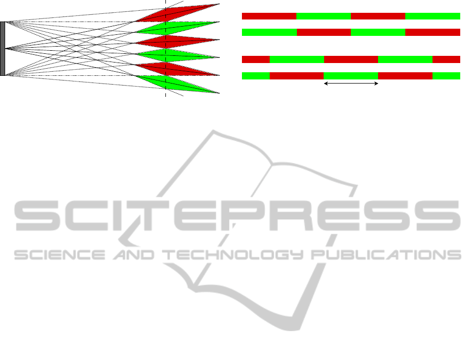
Figure 1: The (doted) rays from the left-most and right-most
end of the screen are limiting the optimal viewing areas for
both eyes. Green: Area where the image for the left eye
is visible. Red: Area for the image of the right eye. The
lines passing through the corners of the rhombuses meet at
the middle of the screen. If the tracking camera is placed
here there is no advantage anymore in determining the eye
depth. See text for more details.
established algorithms with publicly available source-
code. Search areas (e.g. Figure 5) are chosen to work
well for all tested persons plus some extra margin,
while being strict enough to exclude outliers. The sys-
tem can work under different lighting conditions (we
tested it with sunlight as well as infrared light). A ma-
jor benefit of the proposed setup is that the calibration
approach is pixel-wise and thus does not require the
determination of camera and screen parameters. De-
termining such parameters can be complicated espe-
cially if even two cameras must be calibrated to each
other (Andiel et al., 2002).
The paper is structured as follows: In Section 2
we give an overview over our 3D system including
the camera for tracking and the 3D screen. In Sec-
tion 3 we are describing our approach of calibrating
the tracking camera to the 3D screen. In Section 4
we describe the actual eye tracking system in detail.
The eye tracking system includes eye tracking as well
as eye detection elements. While we differ between
the tracking and detection parts in Section 4 the term
“eye tracking” is in other sections only used to refer
to our whole eye tracking system. Finally, we eval-
uate and conclude our approach in Section 5 and 6,
respectively.
2 THE 3D SYSTEM
In this section we describe our 3D system. The sys-
tem consists of the following hardware parts: The 3D
screen, the camera for eye tracking, a PC (Xeon E3
@3.4Ghz) running our software and infrared LEDS
for optional night vision. The software consist of
the eye tracking and calibration system. Our track-
ing camera is a common camera which operates at a
resolution of 1216 x 866 pixels at 50 frames per sec-
Moved barrier:
Unmoved barrier:
Eye
distance
Figure 2: The stripes illustrate the colors on the dashed line
in Figure 1. The width of a stripe is roughly the eye distance
of a human. First row: original screen image. Second row:
images for eyes are swapped. This creates different 3D ar-
eas. In theory every point is covered by these two states. In
practice it will not work in the transit area if the eyes are not
exactly in the depth of the dashed line in Figure 1. This can
be solved by a movable barrier, which gives us in our case
4 different states.
ond. Our 3D screen is based on the parallax barrier
principle (see Fig. 2 in (Neil, 2005)) with multiple
viewing zones (see Figure 1 and Fig. 3/4 in (Neil,
2005)). The barrier of our screen can be moved, so
that we cannot only swap the image for the left and
the right eye but have in common four possible states
(Figure 2). For details on the technology concerning
movable barriers see e.g. (Isono et al., 1993; Yi et al.,
2008). The camera is placed at the intersection point
of the rhombuses (Figure 1). Thereby we do not have
to consider the depth (z value) for calibration and eye
tracking as we can determine the best possible screen
setting directly from pure 2D eye positions. Please
note that although the intersection point in Figure 1
is in the center of the screen we can move the cam-
era freely alongside the parallax barrier stripes (the
dimension not visible in the figure). This allows us to
place it on top of the screen. If the camera position-
ing opposed to the barrier is not accurate the size of
the rhombuses is reduced slightly. In practice, a rough
central placement is sufficient.
3 CALIBRATION
The goal of our calibration approach is to calibrate
(assign) the pixel positions in the camera used for eye
tracking directly to the appropriate states of the 3D
screen. Assigning pixels directly allows us to cal-
ibrate the system without knowing all the relevant
camera and screen parameters. This is a big advan-
tage as the relevant screen parameters might even be
vendor or model specific. To do so, we put the screen
2 meters away parallel to a wall (as this is the optimal
distance of operation, dashed line in Figure 1). Then
VISAPP2015-InternationalConferenceonComputerVisionTheoryandApplications
124
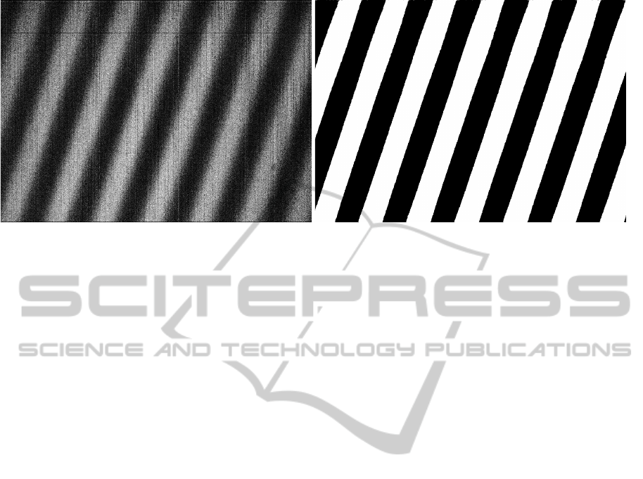
Figure 3: Left: One of the two input images with noise and image artifacts. Right: The resulting stripe pattern.
we render a black image for one eye and a white im-
age for the other eye. In a dark room this creates a
pattern like the one that can be seen in Figure 3 left.
The pattern is too dark to be directly recordable by our
camera. However, we can create the image by taking
several images and averaging their brightness values
to obtain the image I
L
. Then we invert the screen illu-
mination and take another averaged image I
R
. Invert-
ing the screen illumination means that we render a
white image for the eye where we originally rendered
a black image and vice versa. Then we compare I
R
to I
L
. If a pixel is brighter in I
R
than in I
L
we set this
pixel to 1 in a new binary image I
B
. Otherwise we
set the pixel to 0. If we apply a median filter on I
B
to remove single outliers we get the image visible in
Figure 3 on the right side. As can be seen the stripes
are nearly detected perfectly although the original im-
ages are noisy and contain artifacts. I
B
could now be
used to find camera parameters that lead to the deter-
mined pattern. However, this is unnecessary as it is
more accurate and less effort to use I
B
directly instead
of approximating it with a model. In total we create
4 images I
B
for the 4 states in Figure 2 which we call
I
1
B
...I
4
B
. The first two are for the unmoved barrier and
the last two for the moved barrier. Practically we do
not save I
2
B
and I
4
B
as they are just the inverse of I
1
B
and
I
3
B
, respectively.
To determine the correct state for given eye posi-
tions from the eye tracker we first calculate the eye
center position by averaging both eye positions. This
makes sense as there is no advantage in treating them
independently. In the unlikely case where our eye
tracker (described below) only provides the position
of one eye we take the head center (also provided by
our eye tracker) for the x and the eye position as the
y coordinate of the eye center position. To determine
how well the eye center position fits to a state s we
determine the distance of the eye center pixel to the
next white to black transit in the corresponding image
I
s
B
. The state where the transit is the closest from the
eye center pixel is the state that is chosen.
Note that our direct calibration approach is also
suited for displays with freely moving stripes evenif it
only provides two viewing spots at a time (See (Neil,
2005) Fig. 4b) ) . We do not have to record a calibra-
tion pattern for every possible position or state as we
can simply interpolate in between positions/states by
the distances of the eye center position to the white
black transit in the two best fitting calibration pat-
terns.
4 THE EYE TRACKING SYSTEM
In this section we present our eye tracking system,
which is outlined in Figure 4. In the first frame we
perform eye detection to find the positions of the two
eyes. If an eye is detected it is tracked in the next
frame(s), but at the same time we also try to redetect
it.
This helps to get a more accurate position if the
detection and tracking do not lead to the exactly same
position. Furthermore, redetection helps us to update
the appearance model of the tracker – however, we are
not only considering the newly detected position for
model update but also the previous one in our fusion
approach. Thanks to redetection we can also still find
the eye in frames where either tracking or detection
fails. In the subsequent part of this section we will
describe the individual parts of our approach in more
detail. We also describe our prediction approach that
predicts eye positions to eliminate delays.
4.1 Eye Detection
To be able to perform robust and fast eye detection
ASimpleReal-TimeEyeTrackingandCalibrationApproachforAutostereoscopic3DDisplays
125
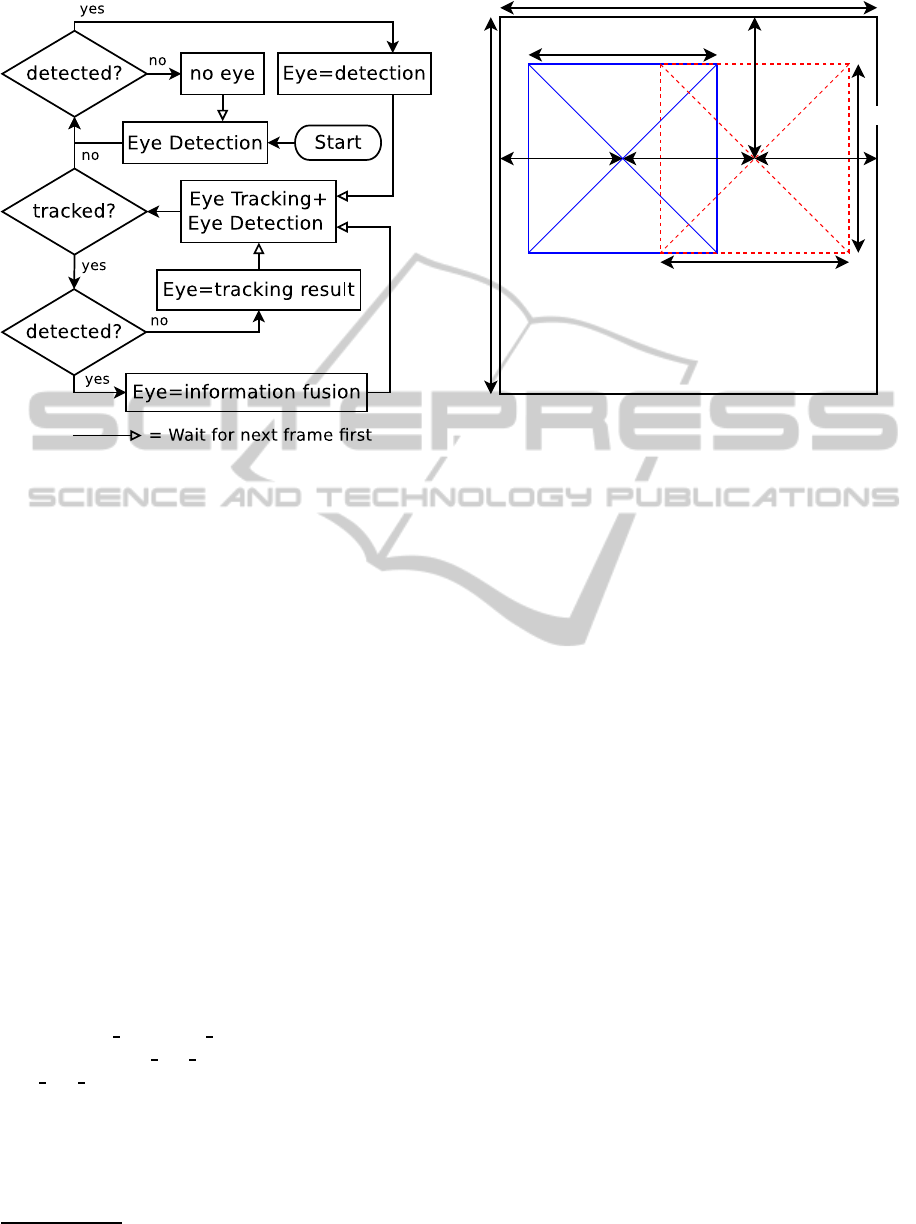
Figure 4: The eye tracking pipeline. “Eye=” means that the
eye position is set from the stated value. “no eye” means
that there is no eye detected in the frame.
we first use face detection to detect face candidates.
Face detection is performed on a scaled-down image
to speed up detection. Scaling down the image usu-
ally does not drop the detection rate much as faces
are much larger than eyes but clearly speeds up detec-
tion. Autostereoscopic displays usually have a limited
working distance. Thus, we are searching the face
only for face sizes that correspond to a distance in the
range of operation ± 20%.
After one or multiple face candidates are found
the eyes are searched in defined areas inside each face
candidate (see Figure 5). If only one eye candidate
is found inside the search area of each eye it is kept.
Otherwise all of them are discarded. As this happens
only seldom with our well chosen search areas we do
not want to risk to choose the wrong one.
For eye and face detection we use Haar fea-
ture based cascade classifiers (Viola and Jones,
2001; Lienhart and Maydt, 2002). More precisely
we are using the following pretrained classifiers
that are publicly available in the OpenCV library
1
:
“haarcascade
frontalface alt.xml” for face detection
and “haarcascade
mcs lefteye.xml” and “haarcas-
cade mcs righteye.xml” for the detection of left and
right eye, respectively. The search size for eyes we
set to be between 0.2 and 0.4 times the face size for
the width and 2/3 of this value for the height.
In our tests we could not find a case where we
found both eyes for false positive face candidates.
1
available at: www.opencv.org
F
F
0.5F
0.5F
0.5F
0.32F 0.32F0.36F
0.38F
Figure 5: The search areas for the left eye (blue) and the
right eye (dashed red) inside the area of a detected face. Val-
ues were determined carefully through experiments. Note
that eyes are determined as areas i.e. the center of an eye
position cannot be in the whole search area.
Thus, we can robustly reject false positives by reject-
ing faces where we cannot find both eyes. If we find
one eye we will reject the detected eye if we either
detect another face with two eyes or if the tracked po-
sition contradicts with the detection. In case of two
persons in the image we prefer the currently tracked
person for a display like ours that supports 3D only
for one person.
4.2 Eye Tracking
Eye tracking is performed by template matching.
Template matching is fast and according to our tests
in our case also more robust and accurate than many
more advanced tracking methods. We found that one
reason for this is the small size (in pixels) of our tem-
plates, which leads to poorer results with many fea-
ture based tracking methods. We also think that the
appearance of eyes of having one central blob is ad-
vantageous for template trackers in case of appear-
ance change. In frames where the eye is detected the
eye template is created or updated from the image de-
tail at the eye position. In frames where there is no de-
tection it is not updated to avoid drifting. For robust-
ness and speed, templates are only matched to a local
image area where the eye is expected. The center of
this area is at the eye position at the last frame plus the
movement between the two last frames if available.
If the matching score of the best position deceeds a
threshold tracking fails without a valid position and
the template is deleted.
VISAPP2015-InternationalConferenceonComputerVisionTheoryandApplications
126

As template matching function we are using Nor-
malized Cross Correlation, which is robust to illumi-
nation changes. In OpenCV this can be easily utilized
by using the “matchTemplate” function. To better be
able to deal with appearance changes template match-
ing is performed with a slightly Gaussian blurred tem-
plate and image. Thanks to the blur, pixels do not
have to fit perfectly and it rather improves matching
accuracy than reducing it.
4.3 Information Fusion
Pixel-wise template matching is usually more accu-
rate in position than object detectors that are based on
coarse image features like Haar or HOG. We cannot
directly benefit from the higher accuracy as the tem-
plate is based on the detection. However, the tracker
allows us to shift the detected eye position from one
frame to the next. The shifted detection can then be
directly compared to the detection in the next frame.
This allows us to average the detected eye positions
of the detector in different frames. Formally the eye
position at a frame n, P
n
is calculated as:
P
n
= S
n
+ T
n
(1)
where T
n
is the tracked position at frame n and S
n
the
shift correction calculated as:
S
n
= round
n
∑
i=n−k+1
S
n
i
/k
!
(2)
S
n
n
= D
n
− T
n
(3)
S
n+i
n
= S
n+i−1
n
− S
n+i
(4)
D
n
is the detected eye position and k the number of
considered previous frames. A template with center
P
n
is used as new tracking template. In case that track-
ing fails the considered frames k must be reset to one.
We define K= k
max
.
4.4 Dealing with Reflections on Glasses
Reflections on glasses caused e.g. by sunlight or in-
frared illumination for tracking in the dark can dis-
tract our tracking and detection methods. The dis-
traction can be reduced significantly by lowering the
brightness value at brightness peaks caused by the re-
flections. To do so we determine for each pixel the
average brightness of its local surrounding (We use
the eye template size as the size of the local surround-
ing. See Section 5 for its size). If a pixel exceeds 3
times the average brightness or has the maximal rep-
resentable brightness value it is considered to be part
of the reflection and is set to the average brightness of
the local surrounding. By using integral images this
approach can be implemented with very low runtime
cost.
4.5 Temporal Prediction
A problem with realtime eye tracking for 3D displays
is that there is a temporal delay i.e. the eye position is
already outdated when calculated. Humans can rec-
ognize even a very short delay well. To prevent the
delay we predict the eye position for a time where
we do not yet have an image from the eye tracking
camera. We test and compare two types of prediction,
simple speed based prediction:
P
(1)
n+i
= P
n
+ i(P
n
− P
n−1
) (5)
and acceleration based prediction:
P
(2)
n+i
= P
n
+ i(P
n
− P
n−1
) + 0.5i
2
(P
n
− 2P
n−1
+ P
n−2
)
(6)
Our system has a delay of around 55 ms. 10 ms be-
cause the average eye position is in the middle of the
exposure. The software delay from starting receiving
a new image from the camera until a new state is send
is around 25 ms (As steps for different frames can be
performed in parallel we can still process more than
50 frames a second). We assume on average 15 ms
delay for the time to the next display refresh plus the
displays reaction time. Furthermore, we calculate 5
ms as extra delay e.g. for the time the graphics card
actually needs to transmit an image. If makes no dif-
ference if the single eye positions are predicted before
eye center calculation or if the eye center position is
predicted directly.
5 EVALUATION
In this section we evaluate the accuracy of our eye
tracking approach. For our tests we use a scale down
factor of 2.5 for face detection. The template size
for eye tracking we set to 0.2F × 0.15F, the template
search area to 0.33F × 0.25F and σ of the template
blur to 0.02F, with F being the detected face size.
Tracking fails if the template matching error for the
best position deceeds 0.8.
Our evaluation results can be seen in Table 1. We
evaluated our tracking approach with 8 different per-
sons and told them to move in different ways. Then
we roughly categorized the different recordings ac-
cording to their movement speed and accelerations.
For “still” only slight movement and no big position
change is allowed. However, people are not artifi-
cially trying to avoid movement completely. Slow
ASimpleReal-TimeEyeTrackingandCalibrationApproachforAutostereoscopic3DDisplays
127
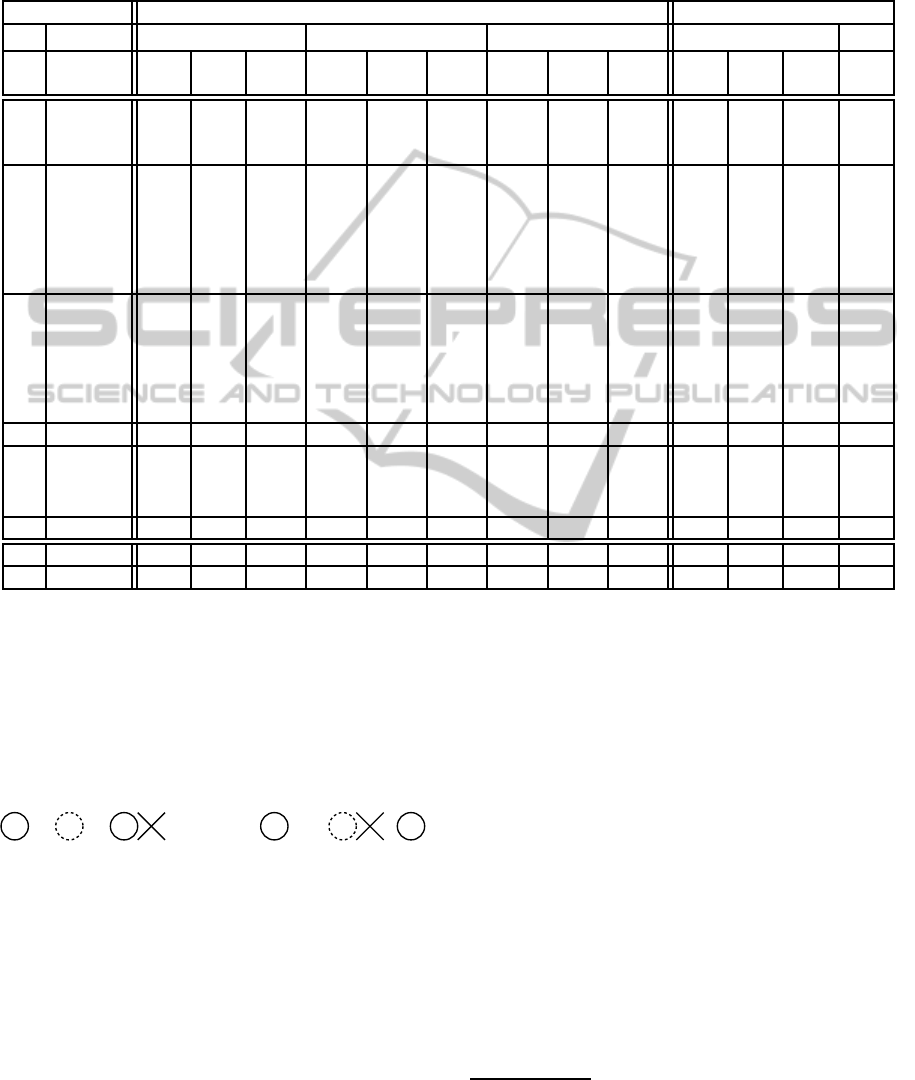
Table 1: Our evaluation results. We evaluated the location error for direct tracking and prediction of 3 frames (60ms). On the
right we show the number of frames that exceed an error threshold. K is set to 2 for these threshold tests. Person 3,7 and 8 are
wearing glasses. Please note that the overall average is strongly influenced by the few fast movement experiments, as there
are great errors with fast movement. We show the overall average for completeness, but practically relevant is the average that
excludes the unnaturally fast movement. The bold numbers show the best value of a K. See text for more details.
Average location error in pixel % frames with pixel error
Direct (P
n
) Speed Pred. P
(1)
n+3
Acc. Pred. P
(2)
n+3
Speed Pred. P
(1)
n+3
P
(2)
n+3
Per-
son
Speed K=1 K=2 K=3 K=1 K=2 K=3 K=1 K=2 K=3 ≥
36
≥
24
≥
18
≥
18
1 still 1.26 1.26 1.14 2.68 1.60 1.25 6.43 2.54 1.83 0.0 0.0 0.0 0.0
3 still 2.53 2.47 2.67 3.67 2.66 2.51 7.97 4.05 3.17 0.0 0.0 0.0 0.0
5 still 0.33 0.28 0.28 1.53 1.17 1.03 5.24 1.74 1.94 0.0 0.0 0.0 0.0
1 slow 0.75 0.67 0.82 2.57 2.25 2.34 6.23 4.31 4.80 0.0 0.0 0.0 2.1
2 slow 1.84 2.10 1.83 3.60 3.03 2.75 7.74 4.52 4.86 0.0 0.0 0.0 3.0
3 slow 1.94 1.78 2.02 2.84 2.80 2.80 6.36 4.91 4.37 0.0 0.0 0.0 2.2
4 slow 0.97 0.73 0.81 2.78 1.57 1.94 7.65 3.76 4.12 0.0 0.0 0.0 0.0
5 slow 0.65 0.59 0.59 2.88 2.42 2.52 6.46 5.13 4.38 0.0 0.0 0.0 0.0
6 slow 1.09 1.14 1.13 2.42 2.03 1.76 5.09 3.58 2.84 0.0 0.0 0.0 0.0
2 middle 1.63 1.89 1.72 6.44 5.60 5.69 9.47 6.61 6.62 0.0 0.0 0.0 4.5
3 middle 1.64 1.42 1.69 7.12 6.44 6.26 11.27 7.94 7.26 0.0 0.0 1.6 9.8
4 middle 0.80 0.64 0.70 3.29 2.56 2.43 6.59 3.83 3.38 0.0 0.0 0.0 0.0
5 middle 0.92 0.88 0.85 3.91 3.65 3.58 7.48 6.45 5.20 0.0 0.0 0.0 8.6
6 middle 0.99 1.09 0.99 4.29 4.01 3.71 6.70 5.31 4.89 0.0 0.0 0.0 5.7
7 middle 1.39 1.31 1.34 5.18 4.46 4.13 10.16 6.94 5.92 0.0 0.0 0.0 3.6
8 still - fast 1.11 0.89 1.19 4.30 4.00 3.99 6.76 4.78 4.78 0.0 1.3 5.1 3.8
1 fast 0.90 0.75 0.97 5.03 4.61 5.53 8.25 7.39 7.80 0.0 5.5 15.0 11.0
2 fast 2.47 3.94 5.08 21.67 20.29 20.62 16.12 13.26
12.85
14.3 35.7 50.0 21.4
4 fast 1.38 1.35 1.76 11.91 11.79 11.35 9.08 10.12 8.93 0.0 4.2 25.0 12.5
7 very fast 9.09 9.33 11.22 32.12 33.12 33.99 64.54 63.07 67.21 23.5 41.2 52.9 64.7
6◦ ≤ middle 1.24 1.20 1.24 3.72 3.14 3.04 7.35 4.77 4.40 0.0 0.1 0.4 2.7
6◦ all 1.68 1.73 1.94 6.51 6.00 6.00 10.78 8.51 8.36 1.9 4.4 7.5 7.6
and middle corresponds to usual movement in front
of the screen if the user wants to change his position
or if he wants to test the 3D effect while moving. Fast
and very fast are unnatural fast movements with very
strong accelerations, that should only happen if one
wants to find the limits of our system. Thus, we show
fast movement only as completion as it is usually ir-
relevant for the practical application.
Figure 6: Circles: two inaccurate detections, one form the
current frame and one shifted from the last frame. Doted
circle: Average position of the two circles. Cross: ground
truth. Only in the right example the doted circle is closer to
the ground truth than the average distance of the two normal
circles to the ground truth. As the position variations of the
eye detector is mostly like on the left (one sided error) there
is no big benefit for our information fusion approach in av-
erage pixel location error. However, the doted circle is less
noisy in position than the original circles which supports
prediction (see text).
The determined pixel error is the error of the eye
center position (the average of both eye potions) com-
pared to labeled ground truth, as the accuracy of the
eye center position and not the accuracy of single eyes
is relevant for our approach. As can be seen in Ta-
ble 1 the pixel location error without prediction is for
natural movement on average only 1.2 pixels (K=1),
which are roughly 0.8 mm. Here, we cannot benefit
much from information fusion on average location er-
ror.
2
Figure 6 shows a likely reason for it. However, if
we use prediction the more stable and less noisy posi-
tion is a real benefit and leads to clearly smaller pixel
location errors especially for acceleration based pre-
diction. Up to K=3 the average location error drops.
For bigger K the shift error of several shifts in a row
(errors are summing up) exceeds the benefit. Without
prediction K=2 is already the limit. Although, accel-
eration based prediction benefits more from informa-
tion fusion it cannot compete with simple speed based
prediction in accuracy. Thus, we practically use speed
based prediction with K=3.
In our tests the measured stripe size was around
2
But in the number of sequences where K=2 and K=3 is
better than K=1 the difference is significant when excluding
fast movement speed.
VISAPP2015-InternationalConferenceonComputerVisionTheoryandApplications
128

96 pixels. Thus, we can allow in the best case 48
in the average case 36 and in the worst case 24 pix-
els location error to be still in a correct screen state.
In Table 1 we also measure the percentage of frames
where the pixel error exceeds a limit (K=3 is used).
In practice it is recommendable to stay below the the-
oretical values. Thus, we also tested for 18 pixels. As
can be seen, even 18 pixels are no problem with speed
based prediction for up to middle movement speed,
while the limit is exceeded several times in differ-
ent sequences with acceleration based prediction. In
contrast, for fast movement speed, acceleration based
prediction is often superior (also in accuracy). Practi-
cally, the user can (due to limit exceedances) see some
flicker for fast movement, mainly when he abruptly
starts or stops moving.
6 CONCLUSION
In this paper we presented an accurate calibration ap-
proach for or autostereoscopic 3D displays that does
not require the knowledge of camera and screen pa-
rameters and is thus very universal and simple to
apply. Furthermore, we presented an easily imple-
mentable but robust eye tracking system. In our eval-
uation we demonstrated its effectiveness. We showed
that it mostly even works for very high movement
speeds. Thanks to the temporal prediction and the
information fusion that improves the prediction accu-
racy even a reaction delay of 60 ms is no real prob-
lem in our realtime autostereoscopic system. In fu-
ture work we plan to expand our system to more com-
plex autostereoscopic displays that can directly adapt
to the users distance to the screen. We, for example,
can determine the interocular distance with our eye
tracker to calculate the rough viewing distance and
calibration could e.g. be performed for two or more
distances and in-between distances could be interpo-
lated.
ACKNOWLEDGEMENT
This work has been partially funded by the BMBF
project Density.
REFERENCES
Andiel, M., Hentschke, S., Elle, T., and Fuchs, E. (2002).
Eye tracking for autostereoscopic displays using web
cams. In Electronic Imaging 2002, pages 200–206.
International Society for Optics and Photonics.
Isono, H., Yasuda, M., and Sasazawa, H. (1993). Au-
tostereoscopic 3-d display using lcd-generated paral-
lax barrier. Electronics and Communications in Japan
(Part II: Electronics), 76(7):77–84.
Li, L., Xu, Y., and Konig, A. (2012). Robust depth cam-
era based multi-user eye tracking for autostereoscopic
displays. In Systems, Signals and Devices (SSD),
2012 9th International Multi-Conference on, pages 1–
6. IEEE.
Lienhart, R. and Maydt, J. (2002). An extended set of haar-
like features for rapid object detection. In Image Pro-
cessing. 2002. Proceedings. 2002 International Con-
ference on, volume 1, pages I–900. IEEE.
Neil, A. (2005). Autostereoscopic 3d displays. Computer,
8:32–36.
Perlin, K., Poultney, C., Kollin, J. S., Kristjansson, D. T.,
and Paxia, S. (2001). Recent advances in the nyu
autostereoscopic display. In Photonics West 2001-
Electronic Imaging, pages 196–203. International So-
ciety for Optics and Photonics.
Su, C.-H., Chen, Y.-S., Hung, Y.-P., Chen, C.-S., and Chen,
J.-H. (2003). A real-time robust eye tracking sys-
tem for autostereoscopic displays using stereo cam-
eras. In Robotics and Automation, 2003. Proceed-
ings. ICRA’03. IEEE International Conference on,
volume 2, pages 1677–1681. IEEE.
Viola, P. and Jones, M. (2001). Rapid object detection using
a boosted cascade of simple features. In Computer Vi-
sion and Pattern Recognition, 2001. CVPR 2001. Pro-
ceedings of the 2001 IEEE Computer Society Confer-
ence on, volume 1, pages I–511. IEEE.
Yi, S.-Y., Chae, H.-B., and Lee, S.-H. (2008). Moving par-
allax barrier design for eye-tracking autostereoscopic
displays. In 3DTV Conference: The True Vision-
Capture, Transmission and Display of 3D Video,
2008, pages 165–168. IEEE.
Zhu, Z., Ji, Q., Fujimura, K., and Lee, K. (2002). Com-
bining kalman filtering and mean shift for real time
eye tracking under active ir illumination. In Pattern
Recognition, 2002. Proceedings. 16th International
Conference on, volume 4, pages 318–321 vol.4.
ASimpleReal-TimeEyeTrackingandCalibrationApproachforAutostereoscopic3DDisplays
129
