Accurate 3D Reconstruction from Naturally Swaying Cameras
Yasunori Nishioka
1
, Fumihiko Sakaue
1
, Jun Sato
1
, Kazuhisa Ishimaru
2
,
Naoki Kawasaki
2
and Noriaki Shirai
3
1
Nagoya Institute of Technology, Nagoya, Japan
2
NIPPON SOKEN INC., 14 Iwaya, Shimohasumi-cho, Nishio, Aichi, Japan
3
DENSO CORPORATION, 1-1, Showa-cho, Kariya, Aichi, Japan
Keywords:
3D Reconstruction, Image Super-resolution, Coded Exposure.
Abstract:
In this paper, we propose a method for reconstructing 3D structure accurately from images taken by un-
intentionally swaying cameras. In this method, image super-resolution and 3D reconstruction are achieved
simultaneously by using series of motion blur images. In addition, we utilize coded exposure in order to
achieve stable super resolution. Furthermore, we show efficient stereo camera arrangement for stable 3D re-
construction from swaying cameras. The experimental results show that the proposed method can reconstruct
3D shape very accurately.
1 INTRODUCTION
The 3D structure recovery is one of the most impor-
tant problem in the field of computer vision. There-
fore, it was widely studied for many applications. In
ordinary case, fixed two or more than 2 cameras, so
called stereo camera systems, are used for 3D re-
construction. These stereo camera systems are cali-
brated in advance, and the relativeposition of cameras
should not be moved after the calibration for measur-
ing 3D structure accurately (Hartley and Zisserman,
2000). However, it is very difficult to fix the relative
position of these cameras perfectly in many applica-
tion systems. For example, when a set of stereo cam-
eras is equipped onto a moving vehicle, these cam-
eras sway independently because of the pitching and
rolling motions of the vehicle. These camera motions
occur unintendedly according to the lack of rigidity
of camera mount systems. Even if the swaying mo-
tions are not large, they often cause serious problems
in 3D measurements, because small amount of cam-
era rotations cause large amount of changes in camera
images. Thus, in ordinary systems, people make large
efforts in stereo system fixation for eliminating these
relative camera motions.
However, the camera motions do not always cause
bad influences, and they sometimes bring good effects
to image processing. For example, camera motions
are very important in image super-resolution (Park
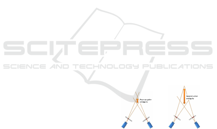
(a) 3D reconstruction from
high resolution images.
(b) 3D reconstruction from
low resolution images.
Figure 1: 3D reconstruction from high and low resolu-
tion images: the ambiguity of 3D reconstruction becomes
smaller when we use high resolution images.
et al., 2003; Glasner et al., 2009). In the image super-
resolution, a high resolution image is reconstructed
from a series of images taken by a moving camera. In
this case, the camera must be moved, since we cannot
obtain additional information from a series of images
taken by a static camera.
In this paper, we propose a method which en-
ables us to reconstruct 3D structures accurately by
positively utilizing the camera motions caused un-
intentionally. In 3D reconstruction, an accuracy of
3D measurement depends on the image resolution of
stereo camera systems as shown in Fig.1. Thus, if we
can generate super-resolution images from uninten-
tionally swaying cameras, we may be able to recon-
struct 3D structures more accurately from stereo im-
551
Nishioka Y., Sakaue F., Sato J., Ishimaru K., Kawasaki N. and Shirai N..
Accurate 3D Reconstruction from Naturally Swaying Cameras.
DOI: 10.5220/0005305805510558
In Proceedings of the 10th International Conference on Computer Vision Theory and Applications (VISAPP-2015), pages 551-558
ISBN: 978-989-758-091-8
Copyright
c
2015 SCITEPRESS (Science and Technology Publications, Lda.)
ages. However, unintentional camera motions are un-
known in general, and they are different in each cam-
era. Moreover, observed images from swaying cam-
eras have motion blur and they lose high frequency
components, which are necessary for accurate 3D re-
construction. Thus, we in this paper propose a method
which enables us to recover camera motions, deblur
images, generate super-resolution images and recon-
struct 3D structure simultaneously by using a series of
images obtained by unintentionally swaying cameras.
The important point of the proposed method is
to use unintentional camera motions positively un-
like the existing stereo reconstruction methods. The
camera motions caused by the shake of camera mount
systems disturb the accuracy of 3D reconstruction in
ordinary stereo camera systems. In contrast, these
camera motions are used positively by combining im-
age super-resolution, camera motion recovery and 3D
reconstruction in the proposed method. Since cam-
eras move unintentionally after camera calibrations in
many real systems, the proposed method is very use-
ful in many applications.
2 3D RECONSTRUCTION FROM
STEREO CAMERA SYSTEMS
2.1 Camera Projection Model and 3D
Reconstruction
We in this section describe a basic theory of 3D re-
construction by using stereo camera systems. At first,
we describe a projection model from a 3D point to a
2D image. The 3D point X is projected onto an image
point x by a camera projection matrix P as follows:
λ
˜
x = P
˜
X (1)
where λ denotes a scale ambiguity and
˜
(·) indicates
the homogeneous representation, e.g.
˜
X = [X
⊤
, 1]
⊤
.
The projection matrix can be represented by an in-
trinsic matrix A, a rotation matrix R and a translation
vector t as follows:
P = A
R t
(2)
When the 3D point X is projected to 2 images as
x
1
and x
2
, a reconstructed 3D point
ˆ
X can be esti-
mated as follows:
ˆ
X = arg
X
min
2
∑
i=1
||P
i
(X) − x
i
||
2
(3)
where P
i
(X) represents projection of X to an i-th cam-
era by a projection matrix. Eq.(3) indicates that the
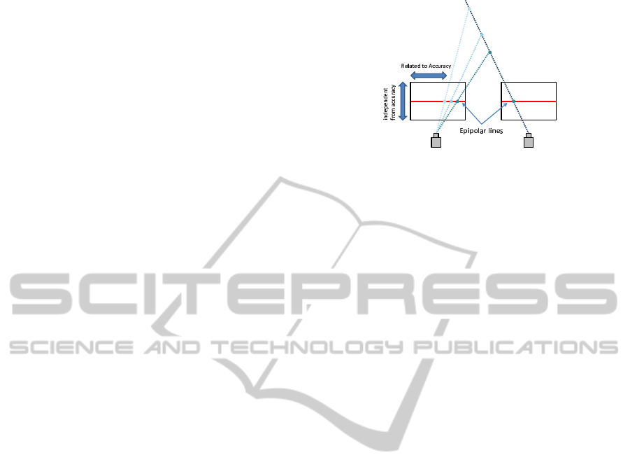
Figure 2: Epipolar Geometry: a point x
1
is on an epipolar
line x
⊤
2
F.
3D point can be estimated by minimizing reprojec-
tion errors. This equation includes non-linear com-
ponents, and thus the minimization can be achieved
by non-linear minimization techniques such as LM
method.
2.2 Epipolar Geometry
We next consider the relationship between multiple
cameras in a stereo camera system. Suppose a 3D
point X is projected to x
1
and x
2
in two cameras.
Then, it is known that the following epipolar con-
straints hold for these corresponding points(Hartley
and Zisserman, 2000):
x
⊤
2
Fx
1
= 0. (4)
where, F is a 3× 3 matrix called fundamental matrix.
This equation shows that a point x
1
/x
2
in the im-
age is on a line called epipolar line, as shown in Fig. 2.
The epipolar line can be estimated from the corre-
sponding point x
2
/x
1
in the other image and the fun-
damental matrix F.
The epipolar geometry represents that correspond-
ing points must be on the epipolar lines. Therefore,
the accuracy of 3D reconstruction depends on the im-
age resolution along the epipolar line as shown in
Fig.2. In other words, we cannot reconstruct 3D shape
accurately, even if the image resolution in the direc-
tion perpendicular to the epipolar line is increased.
Therefore, it is important to increase the image resolu-
tion along epipolar lines for reconstructing 3D struc-
tures accurately.
3 IMAGE SUPER RESOLUTION
FROM NATURALLY SWAYING
CAMERAS
3.1 Motion Representation by PSF
For accurate 3D reconstruction from a series of im-
VISAPP2015-InternationalConferenceonComputerVisionTheoryandApplications
552

ages taken by swaying cameras, we consider image
super resolution. When images are taken by a moving
camera, these images include independent informa-
tion, since these images are obtained from different
sampling points in the original 3D scene. Therefore,
we can recover images which include high frequency
components from the series of images, i.e. high res-
olution images. However, we cannot ignore motion
blur in images, which is caused by the camera mo-
tion(Bando et al., 2011; Cho and Lee, 2009). There-
fore, we also estimate the motion blur for generating
high resolution images in this paper.
The motion blur can be represented by convolu-
tion of original image and PSF (Point Spread Func-
tion). Therefore, the estimation of motion blur is
equivalent to the estimation of PSF. In addition, the
PSF can represent not only motion blur, but also cam-
era motion when the motion of camera is sufficiently
small. In this paper, we assume that the motion
of camera in two consecutive frames is sufficiently
small, and represent both camera motion and motion
blur by using the PSF.
3.2 Evaluation Function
We next define an evaluation function for image
super-resolution. Suppose we have a height resolution
image, I
h
, and it is down-sampled by a moving cam-
era obtaining K sampled images I
k
(k = 1, ··· , K).
Then, what we want to do is to recover the origi-
nal height resolution image, I
h
, from input images I
k
(k = 1, ··· , K). For this objective, we define an eval-
uation function E
s
as follows:
E
s
=
∑
k
||I
k
− D(I
h
, B(R
k
, t
k
))||
2
+ E
c
. (5)
The first term of this equation is a data term and the
second term E
c
is a regularization term. In the data
term, the high resolution image I
h
is down-sampled
by function D and compared with the input images.
B denotes the PSF defined by the motion parameters,
R
k
and t
k
, of the camera in the k-th image. The sec-
ond term is a regularizer of this estimation, and it is
a smoothness constraint, such as image derivative, in
ordinary cases. In this paper, we estimate the high
resolution image I
h
and the PSF B form input images
I
k
(k = 1, · · · , K).
When a camera translation is sufficiently small,
the camera motion can be represented just by a ro-
tation. In this case, the PSF of a whole image can be
represented by a single PSF. In this paper, we assume
that the camera motion can be represented by a ro-
tation. Therefore, down-sampling function D can be
represented approximately as follows:
D(I
h
, B(R
k
, t
k
)) ∼ D(I
h
, B(R
k
)) (6)
By minimizing the evaluation function E
s
, we can es-
timate camera rotation R
k
and high resolution image
I
h
simultaneously.
3.3 Linear Representation of
Evaluation Function
The evaluation function described in the previous sec-
tion can be represented by a linear function. In this
section, we describe the detail of this linear represen-
tation.
We first describe a linear representation of down-
sampling D. The image blur represented by a PSF can
be described by an image convolution and the convo-
lution can be represented by a matrix computation.
Let us describe the convolution of PSF and high reso-
lution image I
h
by using a PSF matrix B as follows:
I
h
b
= B(R)I
h
(7)
where I
h
b
is a blurred image of I
h
, and B(R) is a PSF
matrix determined by the camera motion R. Note that,
the PSF matrix B is an (N × M) × (N × M) matrix
when the resolution of I
h
is N × M. Each row of B
represents the PSF of each image pixel.
After blurring the image by matrix B, the blurred
image is down-sampled by a down-sampling matrix
D as follows:
I
d
b
= DB(R)I
h
(8)
where I
d
b
is a blurred and down-sampled image of I
h
.
The matrix D is an (N
′
× M
′
) × (N × M) matrix when
the resolution of the down-sampled image I
d
b
is N
′
×
M
′
. The down-sampled image I
d
b
is compared with
the input image, and their similarity is evaluated as
follows:
||I
k
− DB(R)I
h
||
2
(9)
We next consider the linear representation of the
regularization term E
c
. This term is represented by
the derivatives of high resolution image as follows:
∆
x
I = S
x
I
h
(10)
∆
y
I = S
y
I
h
(11)
where ∆
x
I and ∆
y
I represent derivatives of I
h
in x and
y directions respectively, and S
x
and S
y
are matrices
which represent discrete derivative in x and y direc-
tions. When the image is sufficiently smooth, these
derivatives also become small. Therefore, we can de-
scribe the regularization term by a linear representa-
tion as follows:
||S
x
I
h
||
2
+ ||S
y
I
h
||
2
. (12)
We can finally obtain the linear representation of
E
s
in Eq.(5) as follows:
E
s
=
∑
k
||I
k
− DB(R
k
)I
h
||
2
+ ||S
x
I
h
||
2
+ ||S
y
I
h
||
2
.
(13)
Accurate3DReconstructionfromNaturallySwayingCameras
553

The evaluation function E
s
can be minimized by an
ordinary least square means method easily. As a re-
sult, we can estimate high resolution image I
h
from
low resolution images I
k
.
4 3D RECONSTRUCTION WITH
SUPER RESOLUTION
4.1 Simultaneous Estimation of High
Resolution Image and Accurate 3D
Structure
We next consider a method for reconstructing 3D
structures accurately from a series of images. This
is achieved by reconstructing 3D structures and gen-
erating super-resolution images simultaneously.
As we explained in the previous section, we can
estimate not only high resolution images, but also
camera motion parameters from blurred images ob-
tained in each camera. However, the camera motion
parameters can also be estimated from the geomet-
ric constraint, i.e. epipolar geometry, in our method.
Since the image super resolution, camera motion es-
timation and the 3D reconstruction are closely related
to each other, these must be estimated simultaneously
for accurate 3D reconstruction. In the following sec-
tions, we propose a method for estimating 3D struc-
tures, camera motions and super-resolution images si-
multaneously.
4.2 3D Reconstruction with Image
Super-resolution
For simultaneous estimation of high resolution im-
ages, camera motion parameters and accurate 3D
structures, we define the evaluation function as fol-
lows:
E
r
= E
s
+ E
b
(14)
where E
s
is the evaluation value of image super-
resolution defined by Eq.(5) and E
b
is the evaluation
value of 3D reconstruction. The evaluation value E
b
is defined as a reprojection error as follows:
E
b
=
∑
i
∑
j
||x
i
j
− P (R
i
, t
i
, X
j
)||
2
(15)
where x
i
j
denotes a j-th image point in i-th image, and
P (R
i
, t
i
, X
j
) indicates the projection of a 3D point X
j
to the i-th camera whose rotation is R
i
and transla-
tion is t
i
. In the ordinary 3D reconstruction method so
called bundle adjustment(Triggs et al., 1999; Agarwal
et al., 2011), a set of 3D points X
j
and camera param-
eters R
i
, t
i
are estimated by minimizing the reprojec-
tion error.
In our proposed method, we consider not only
geometric reprojection error E
b
, but also the evalua-
tion value of image super-resolution E
s
. By minimiz-
ing E
b
, we can estimate 3D structures, camera mo-
tions and super-resolution images efficiently and ac-
curately.
4.3 Minimizing Method
In order to minimize E
r
in Eq.(14), we use an itera-
tive minimization technique, in which E
s
and E
b
are
minimized iteratively. It is difficult to minimize E
s
and E
b
simultaneously because corresponding points
used in E
b
minimization strongly depend on the re-
sults of image super-resolution. Thus, we minimize
E
s
and E
b
iteratively.
In this method, we first detect corresponding
points x
i
j
by using feature point detector, such as SIFT
in input images. By using the corresponding points,
3D structures and camera motion parameters are esti-
mated by minimizing E
b
.
We next estimate super-resolution image by min-
imizing E
s
by using the motion parameters estimated
by the previous geometric estimation. In this estima-
tion, high resolution image and motion parameters are
updated by using blurred images.
After that, corresponding points are extracted
from the estimated high resolution images, and 3D
structures and camera motion parameters are esti-
mated again by minimizing E
b
. By iterating these
procedures, we can estimate super-resolution images,
camera motion parameters and 3D structures simulta-
neously.
5 SEVERAL TECHNIQUES FOR
EFFECTIVE ESTIMATION
5.1 Controlling Camera Motion
In order to achieve stable recovery of 3D structures
and high resolution images, we add several techniques
into the proposed method. We first consider the re-
striction of camera motions.
As we described in Sec.2.2, we only need to in-
crease the image resolution along with the epipolar
line. For example, if the epipolar lines are parallel
to x axis, we only need to increase the resolution in x
axis. Also, we cannot increase the image resolution in
x axis, when the camera motion occurs along y axis.
VISAPP2015-InternationalConferenceonComputerVisionTheoryandApplications
554
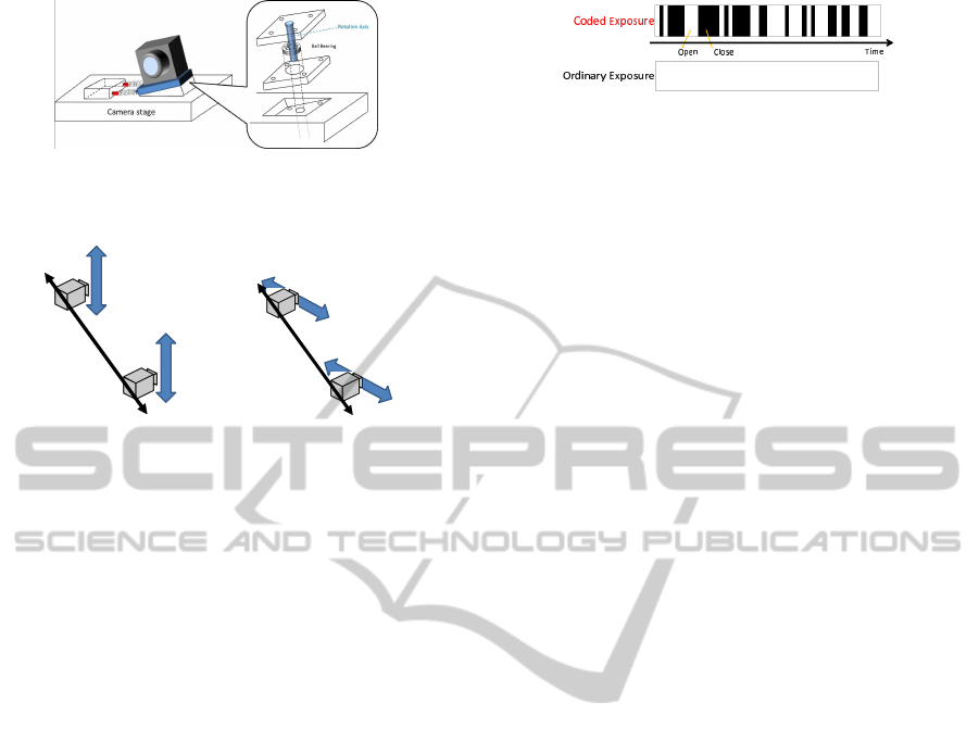
Figure 3: 1DoF camera swaying stage: By using this stage,
unintentional camera rotations can be limited around a sin-
gle rotation axis.
(a) Example of camera
arrangement
(b) Example of camera
arrangement
Figure 4: Examples of effective camera arrangement: In
these arrangements, the epipolar lines and camera swaying
direction are neither parallel nor orthogonal to each other.
Thus, we restrict the direction of camera motions, al-
though they occurs unintentionally. For this objec-
tive, we in this paper use a camera stage, which allows
camera to rotate only in 1 axis as shown in Fig.3. Fur-
thermore, the stage is connected with a spring, which
controls the frequency of the swaying motion of the
camera. As a result, the series of camera rotation can
be parametrized by a small number of parameters be-
cause of characteristic of a spring. When the spring
sway with its characteristic vibration, the motion can
be represented by phase φ, frequency f and amplitude
λ. Therefore, we can estimate series of camera rota-
tion only by estimating these 3 parameters.
5.2 Camera Arrangement
We next consider the camera arrangement for our
stereo camera system. As described in the previous
section, we can reconstruct 3D structures effectively
when the camera swaying direction is parallel to the
epioplar lines. Therefore, it seems that the cameras
should be arranged along with swaying direction at
a glance. However, we cannot reconstruct 3D struc-
tures nor estimate camera motions under this condi-
tion. This is a degenerate case in the structure and mo-
tions, and the 3D geometry and camera motions can-
not be estimated uniquely from camera images (May-
bank, 1993).
In order to avoid this problem, the epipolar lines
defined by the camera arrangement should not be par-
allel to the swaying direction of cameras. For exam-
Figure 5: Example of coded exposure.
ple, we can estimate these parameters when cameras
are arranged as shown in Fig.4 In these arrangements,
camera swaying direction is neither orthogonal nor
parallel to the epipolar lines in each image, and thus,
we can estimate high resolution images and accurate
3D structures simultaneously.
5.3 Coded Exposure for Stable Image
Reconstruction
Finally, we consider the image exposure in the pro-
posed method. Figure 7(a) shows some examples of
input images and their PSFs obtained under swaying
motions of a camera. In this figure, the color of PSFs
under example images shows the intensity of PSFs as
shown in the right color bar. These examples indi-
cate that input images and their PSFs are very similar
to each other under the swaying motion of camera.
In this case, these input images do not have much
independent information, and thus, we cannot esti-
mate high resolution images effectively. In order to
avoid this problem, we in this paper use a coded ex-
posure (Raskar et al., 2006; Naito et al., 2012; Liang
et al., 2008).
The coded exposure is one of the techniquefor sta-
ble estimation of motion blur. In this technique, the
shutter of camera is opened and closed many times
while taking a single image. Figure.5 shows an ex-
ample of coded exposure. In this figure, white regions
indicate shutter opening time and black regions indi-
cate shutter closing time. In normal exposure, cam-
era shutter is opened continuously while taking an
image. In contrast, the shutter is closed and opened
many times in coded exposure. As a result, the fre-
quency characteristics become much better than the
normal exposure as shown in Fig.6. This figure in-
dicates power spectrum of each exposure technique.
When we use the normal exposure, several zero cross
occur in frequency space, and thus, some components
in high resolution image cannot be estimated stably.
In contrast, the frequency characteristics of the coded
exposure are flat and high, and thus, we can recon-
struct motion blur effectively.
By using this coded aperture, we can obtain better
images for motion blur estimation and reconstruction.
In addition, we can obtain images including different
information from each other. Figure 7 shows exam-
ples of series of input images by using normal ex-
Accurate3DReconstructionfromNaturallySwayingCameras
555
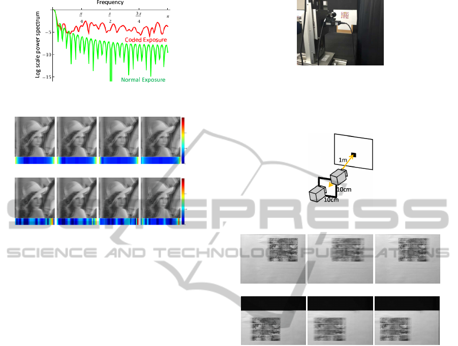
Figure 6: Power spectrum of exposure.
(a) Input images and PSFs under normal exposure.
(b) Input images and PSFs under coded exposure.
Figure 7: Examples of input images and PSFs: The input
images obtained by the normal exposure are similar to each
other, while those obtained by the coded exposure are very
different from each other.
posure and coded exposure. While the normal expo-
sure provides us similar images, the coded exposure
provides us different images as shown in this figure.
Therefore, we can reconstruct high resolution images
from the series of images taken by swaying cameras.
Note that, the exposure pattern is optimized for
camera motions in the existing methods. However,
we cannot optimize the pattern because the camera
motions change and are unknown in the proposed
method. Therefore, we use random coded exposure
in our method. Although the random exposure may
not provide us the best PSF, it can provide us much
better PSF than the normal constant exposure.
6 EXPERIMENTS
6.1 Real Image Experiments
In this section, we show results from 3D reconstruc-
tion experiments using real images. In this experi-
ment, we used a translation and rotation stage shown
in Fig.8. By using this stage, the camera was moved
as shown in Fig.9, and constructed a pair of stereo
cameras, whose vertical distance is 10 cm and the hor-
izontal distance is 10 cm. The camera is rotated at
each camera position for generating the swaying mo-
tions, and series of images are taken at each position.
Figure 8: Translation and rotation stage. The camera was
moved in horizontal and vertical direction by using the stage
and a set of stereo cameras was constructed. In addition, a
rotation stage was equipped on the translation stage, and the
swaying motions of cameras was generated.
Figure 9: Stereo camera setting.
(a) Example images at left camera position.
(b) Example images at right camera position.
Figure 10: Examples of input images.
The frequency of the rotational motion was 10.5 Hz,
the amplitude was 1.0 degree, and the phase was 0
degrees respectively. The angle between the epipolar
line and the camera swaying direction was 45 degrees.
The pattern of the coded exposure is random pat-
tern. The resolution of input images was 320 × 240,
and 1280× 240 images were reconstructed from 8 se-
quential images by using the proposed method. Fig-
ure 10 shows examples of the series of input images
at each camera position. From these images, we re-
constructed a planar object. The depth of the planar
object was about 1000 mm.
Figure 11 shows reconstructed high resolution im-
ages by the proposed method. The results show that
the proposed method can reconstruct high resolution
images.
Table 1 shows 3D reconstruction errors. For com-
parison, we reconstructed 3D structures by using the
proposed method and the ordinary stereo reconstruc-
tion method which uses low resolution image de-
blurred from a single blurred image. We also re-
VISAPP2015-InternationalConferenceonComputerVisionTheoryandApplications
556

(a) SR image of left position
(b) SR image of right position
Figure 11: Super-resolution images reconstructed by the
proposed method.
Table 1: The recovered distance and errors in the proposed
method, the ordinary stereo reconstruction method and the
ground truth. The ground truth distance was measured from
high resolution images without motion blur.
proposed ordinary ground
method method method truth
distance [mm] 995.1 999.0 983.5
error [mm] 11.6 15.5 0
covered 3D structures by using high resolution im-
ages without motion blur, and considered them as the
ground truth. Table 1 shows that the average depth
of the proposed method is more close to the ground
truth, and hence it is more accurate than the ordinary
stereo reconstruction method.
Figure 12 shows the results of 3D reconstruction
in each method. In this figure, reconstructed 3D
points are represented by a 2D image, where the verti-
cal axis shows Z axis and the horizontal axis shows X
axis in the 3D space. The results show that 3D points
reconstructed by the proposed method are much more
close to the ground truth plane, while the 3D points
reconstructed from the low resolution images are far
from the ground truth plane. Thus, we find that our
method can reconstruct 3D points more accurately
than the ordinary reconstruction method, and it can
use unintentional camera swaying motions efficiently
for improving the accuracy of 3D reconstruction.
−100 −80 −60 −40 −20 0 20 40 60 80 100
975
980
985
990
995
1000
1005
1010
x
z
ground truth
ordinary method
proposed method
Figure 12: 3D reconstruction results: Vertical axis of this
figure indicate depth axis in 3D space and horizontal axis
indicates horizontal axis of 3D space.
6.2 Experiments in Synthesized
Environment
We next show experimental results under synthesized
environment. In this experiment, two cameras were
arranged as shown in Fig.13. These cameras are
swaying horizontally, and thus, the input images in-
clude horizontal motion blur. The rotation parameters
of these cameras are the same as those in the previ-
ous experiment. Thus, the angle between the epipo-
lar lines and the camera swaying direction in the im-
age was 45 degrees. The frame rate of these cameras
was 30 fps. Frequencies of the cameras were 9.9Hz
and 8.1Hz. The magnitudes of the motions were 0.9
degrees and 1.1 degrees. The phases of the motions
were 0.53 degrees and 1.05 degrees. The pattern of
the coded exposure is random pattern.
Figure 14 shows examples of input images from
the left and the right cameras. The resolutions of in-
put images were 200 × 150. By using 8 sequential
images, we reconstructed 800× 150 image pair. The
relative camera positions were calibrated beforehand,
and thus we just estimated camera rotations in the pro-
posed method. The corresponding points in images
were extracted by using the SIFT feature detector.
Target object in this experiment is a plane and texture
image as shown in Fig.13 are mapped onto this plane.
For comparison, the 3D structure of the target plane
was reconstructed by using the proposed method and
the ordinary stereo method which uses low resolution
images deblurred from a single blurred image.
We first show the results of image super-resolution
in Fig. 15. As shown in these images, we obtained
very sharp high resolution images, and thus we find
that the proposed method can reconstruct super reso-
lution images from series of images taken by uninten-
tionally swaying cameras. Table 2 shows the accuracy
of 3D reconstruction in the proposed method and the
ordinary stereo reconstruction method. The error in-
dicates the average distances from the ground truth of
a target plane. These results show that the proposed
method can reconstruct 3D structures more accurately
than the ordinary stereo reconstruction method, even
if the series of input images include motion blur. As
the results, we find that the proposed method can re-
construct 3D structures and super-resolution images
simultaneously from unintentionally swaying cam-
eras.
7 CONCLUSIONS
In this paper, we proposed a method for reconstruct-
ing 3D structures accurately by using unintentionally
Accurate3DReconstructionfromNaturallySwayingCameras
557
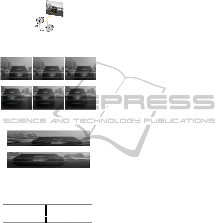
Figure 13: Experimental environment: In this environment,
an angle between the epipolar line and the camera swaying
direction is 45 degree.
(a) Input images from a left camera.
(b) Input images from a right camera.
Figure 14: Examples of input images.
(a) SR image of left camera
(b) SR image of right camera
Figure 15: Super-resolution images reconstructed by the
proposed method.
Table 2: 3D reconstruction errors in the proposed method
and the ordinary stereo reconstruction method.
proposed ordinary
method
method method
average error[mm] 26.8 42.0
swaying stereo camera systems. In this method, cam-
eras are swaying naturally and they take series of im-
ages including motion blur. From the series of im-
ages, high resolution images and accurate 3D struc-
ture are obtained simultaneously. In this proposed
method, we use 1 DoF swaying stage for control-
ling camera rotation. In addition, coded exposure is
used for stable image super-resolution. The image su-
per resolution and 3D reconstruction are achieved si-
multaneously because both estimations need the same
camera motion parameters. The experimental results
show that the proposed method can reconstruct high
resolution images and accurate 3D structures simulta-
neously.
REFERENCES
Agarwal, S., Furukawa, Y., Snavely, N., Simon, I., Curless,
B., Seitz, S. M., and Szeliski, R. (2011). Building
rome in a day. Commun. ACM, 54(10):105–112.
Bando, Y., Chen, B.-Y., and Nishita, T. (2011). Motion
deblurring from a single image using circular sensor
motion. Computer Graphics Forum (Proceedings of
Pacific Graphics), 30(7):1869–1878.
Cho, S. and Lee, S. (2009). Fast motion deblurring. Trans-
actions on Graphics, 28:145.
Glasner, D., Bagon, S., and Irani, M. (2009). Super-
resolution from a single image. In Proc. ICCV.
Hartley, R. and Zisserman, A. (2000). Multiple View Geom-
etry in Computer Vision. Cambridge University Press.
Liang, C., Lin, T., Wong, B., Liu, C., and Chen, H.
(2008). Programmable aperture photography: Mul-
tiplexed light field acquisition. In SIGGRAPH, ACM
Transactions on Graphics.
Maybank, S. (1993). Theory of Reconstruction from Image
Motion. Springer-verlag.
Naito, R., Kobayashi, T., Sakaue, F., and Sato, J. (2012).
Deblurring depth blur and motion blur simultaneously
by using space-time coding. In ICPR, pages 2177–
2180.
Park, S., Park, M., and Kang, M. (2003). Super-resolution
image reconstruction: A technical overview. IEEE
Signal Processing Magazine, 20(3):21–36.
Raskar, R., Agrawal, A., and Tumblin, J. (2006). Coded
exposure photography: Motion deblurring using flut-
tered shutter. In ACM SIGGRAPH 2006 Papers, SIG-
GRAPH ’06, pages 795–804, New York, NY, USA.
ACM.
Triggs, B., McLauchlan, P., Hartley, R., and Fitzgibbon, A.
(1999). Bundle adjustment - a modern synthesis. In
Proceedings of the International Workshop on Vision
Algorithms.
VISAPP2015-InternationalConferenceonComputerVisionTheoryandApplications
558
