
EM410x RFID Cloned Card Detection System
Michal Krumnikl, Pavel Moravec, Petr Olivka and David Seidl
V
ˇ
SB - Technical University of Ostrava, Faculty of Electrical Engineering and Computer Science,
17. listopadu 15, 708 33 Ostrava-Poruba, Czech Republic
Keywords:
RFID, EM410x, Security, Cloned Card Detection, Low-cost.
Abstract:
RFID tags are nowadays used for granting access to buildings, tracking goods, persons and animals, in elec-
tronic toll collection systems, mobile payments, and other application areas. The purpose of this paper is to
propose a solution that is capable of detecting fake (cloned) low cost 125 kHz RFID tags. The paper is fo-
cusing on detecting clones and emulators of EM410x tags. The proposed method is based on modifying the
RFID reader and exploiting the specific features and properties of the fake tags. The experiments performed
with the RFID reader with the implementation of the proposed clone detection techniques have shown that it is
possible to reliably detect the majority of the publicly available fake tags and emulators. Moreover, the reader
is capable of deactivating some of the clone tags if necessary.
1 INTRODUCTION
Radio frequency identification (RFID) is a widely
used technology for identifying objects using a com-
bination of RFID tags, readers, and appropriate soft-
ware applications. Initially, the RFID tags were de-
veloped to replace the printed barcodes in the sup-
ply chain management. Their main advantages are
that they can be read wirelessly and can contain much
more information than the standard barcodes.
Nowadays, RFID tags are also used for granting
access to buildings, tracking goods, persons and an-
imals, in electronic toll collection systems, mobile
payments, etc. The main factor that drove a signifi-
cant increase in RFID usage is the decreasing cost of
the necessary equipment and tags. Nevertheless, the
tags are also vulnerable to various attacks that are be-
coming more widespread as the number of RFID ap-
plications increases. In systems that are vulnerable to
tag cloning, the attacker may gain access to a secured
area, make fraudulent payments, or disrupt the sup-
ply chain. For companies, the possibility of cloning
the RFID tags is a major threat. Therefore, the re-
searchers have come up with several techniques that
increase the privacy and security of the RFID systems.
1.1 Related Work
There is a huge variety of available tags, differing in
size, casing, memory and processor. Some of them
provide high-end cryptographic features such as a
public key infrastructure, SHA hashing functions or
AES, 3DES, RSA cryptographic algorithms. As the
number of applications increases, the number of at-
tacks against the tags and readers increases as well.
For example, Mifare Classic tags were very popu-
lar in the past, but nowadays are considered inse-
cure (Hancke, 2005; de Koning Gans et al., 2008).
The cloning is not the only problem. The practical
approaches of eavesdropping, unauthorized scanning
and relay attacks on ISO 14443-A tokens and the RF
layer were described in (Hancke, 2006; Issovits and
Hutter, 2011). The improved version of the Mifare
DESFire, considered as a replacement for insecure
Mifare Classic, was broken in a short time by using
a non-invasive power analysis and template attacks
(Oswald and Paar, 2011). Other standards, e.g. HID
iClass has also some fundamental flaws described in
(Garcia et al., 2012) and the RFID tags embedded in
the car keys have been also found insecure (Verdult
et al., 2012). And these are only the most notable ex-
amples of the known vulnerabilities. The well known
weaknesses of the RFID systems are summarized in a
detailed survey by (Mitrokotsa et al., 2010).
In general, the more advanced the tag is (in sense
of security and privacy), the more it costs. Therefore,
due to the economic constraints, most of the RFID
tags used in the supply chains emit only the raw data
(usually the tag ID) without any authentication or en-
cryption. These tags, such as EM410x, are targets
of our paper. As these types of tags do not employ
any security features, the cloning involves copying the
76
Krumnikl M., Moravec P., Olivka P. and Seidl D..
EM410x RFID Cloned Card Detection System.
DOI: 10.5220/0005229700760082
In Proceedings of the 5th International Conference on Pervasive and Embedded Computing and Communication Systems (PECCS-2015), pages 76-82
ISBN: 978-989-758-084-0
Copyright
c
2015 SCITEPRESS (Science and Technology Publications, Lda.)

tag’s ID and its associated data (Koscher et al., 2009).
At present, there are several easily available tools for
cloning and emulating various tags. As a result, the
researches have focused on methods for detecting the
counterfeits.
There are two types of anti-counterfeiting solu-
tions: (i) based on the tag-authentication methods and
(ii) based on the track-and-trace data within the RFID
tag (Lehtonen et al., 2009; Blass et al., 2011; Zanetti
et al., 2013). The former approach is aimed at mak-
ing the tag cloning harder through the use of various
cryptographic primitives. This is the approach typical
for the smart HF tags. The latter, which is typical for
the low cost LF tags, is aimed at detecting clones by
verifying tag behaviours and its path across the sup-
ply chain (however, tag-related data must be available
among the supply chain partners). Such solutions tar-
get mainly the pharmaceutical supplies (Koh et al.,
2003; Mackey and Liang, 2011). The pharmaceuti-
cal companies are nowadays employing RFID tech-
nology to protect their supply chains from counter-
feit drugs. Some market researches indicate that up to
ten percent (Interpol indicates even 30 percent) of the
drugs sold worldwide can be counterfeits.
This paper is focused on detecting clones of
cheap, low frequency EM410x tags. They are not
addressed by the recent studies as they are read-only
tags and do not provide any way of storing track-and-
trace data. The use of these tags for security sen-
sitive application is not recommended, as they were
never considered to be secure. However, they are still
frequently used for entrance and identification sys-
tems in many organizations, libraries and universities.
Moreover, they are used up today in several home se-
curity systems as the entry cards (e.g. Jablotron PC-
01). Based on their frequent use, we believe it is still
beneficial to discuss the possibilities of improving the
security of such systems.
1.2 Contribution of this Paper
The purpose of this paper is to propose a solution that
is capable of detecting cloned tags and emulators. The
method is based on modifying the RFID reader and
exploiting the specific features and properties of the
fake tags.
Our solution is designed as an off-line system as
the systems that work exclusively with the on-line
readers are easier to protect than the off-line systems
that are unable to perform real-time checks against
the blacklist database. Therefore, we have focused on
improving the possibilities of detecting and intercept-
ing the fake tags by the off-line readers. The herein
proposed card reader is performing a series of tests
to check the limits and reactions to the signals (in-
puts) that are not defined or are out of the range of the
original tag specification. The main idea is to detect
specific states that are typical only for the fake tags.
The remaining parts of the paper are organized as
follows: Section 2 contains the basic operation prin-
ciples of the tags and their fake counterparts. The ba-
sic principles of the proposed fake tag detection tech-
niques are described in the following Section 3. The
results of the experiments with the proposed fake tag
detection reader can be found in Section 4. The con-
tribution of this paper is summarised in Section 5.
2 EM410X TAGS OPERATION
EM410x tags are low frequency tags (widely used in
plastic cards) which are much more simpler than the
high frequency ones described in the previous Section
1.1. EM4100/4102/4105/4200 tags are developed by
EM Microelectronic. The tag contains a contactless
transponder carrying 64 bits of read only memory
without use of encryption. The programming of the
chip is performed by the manufacturer by laser fus-
ing of poly silicon links. By this way, an unique code
is assigned to each individual chip. The memory is
organized into a 9 bit header, 40 bits of data (unique
ID), 14 parity bits, and one stop bit. The output is
modulated using the Manchester coding with a bit rate
corresponding to 64 cpb (carrier cycles per bit). The
tag uses 125 kHz carrier with ASK (amplitude-shift
keying) modulation. An example of the modulation is
depicted in Figure 1. The tag is transmitting data as
long as it is in the range of the readers electromagnetic
field (EM Microelectronic-Marin SA, 2004).
Figure 1: Measured initialization sequence of the EM410x
tag. The Manchester encoding of the first header bits is
clearly visible. Notice that the tag starts the transmission
140 µs after turning the RF field on. The importance of the
timing will be described later on in Section 3.
EM410xRFIDClonedCardDetectionSystem
77

2.1 Programmable Tags
The majority of the programmable tags (used
as clones) sold on eBay are based on the
E5550-compatible OTP identification circuit (e.g.
ATA5557/5567/5577, etc.) It is a contactless chip
working in the 125 kHz range, providing a bidi-
rectional communication with ability to be repro-
grammed by the base station. Once the chip is pro-
grammed and locked, it operates as the standard read-
only tag.
The programming occurs via the write method
based on interrupting the RF field with the short gaps
(on-off carrier keying). The time between the gaps en-
codes the bits of transmitted configuration. The write
mode is triggered by the initial start gap and can be
detected by the permanently enabled damping of the
RF field during the write mode (Atmel Corporation,
2014). See Figure 2 for more details of the tag modes.
2.2 Clones Based on Microcontrollers
Since the normal tag operation is very simple to emu-
late, it is quite easy to construct a device operating in
the same manner. There are several well documented
constructions on the Internet blogs and forums based
on Microchip and Atmel controllers.
In the simplest form, the microcontroller (MCU)
is connected only to the coil. The MCU is pow-
ered through its protective clamping diodes, while the
power is retained by the die’s internal capacitance. In
the same way, the CPU core is directly clocked by
the signal from the coil (Dowty, 2010). The firmware
itself is very interesting, since it contains only the in-
structions for enabling and disabling the output pin
connected to the coil, thus alternatively damping it
(providing the ASK modulation).
The alternative approaches do not use the carrier
signal as the clock source and use their own internal
or external oscillators for proper clocking (Krumnikl,
2007). The correct timing is therefore not dependent
on the carrier frequency, so the processor can work
on much higher speeds, providing enough power for
additional functions.
The RFID emulators are configured using a DIP
switch or can be even equipped with a small display
and simple keys for changing its modes, emulated
data etc.
3 CLONE/FAKE DETECTION
In order to prevent the use of clones (programmable
tags) and tag emulators, we have to construct a reader
capable of detecting such counterfeit tags. Beside
the main function (reading the ID from the tag), the
reader also tries to detect the clones and card emu-
lators by changing the carrier frequency and timing,
generating mode switch commands and monitoring
the responses. The reader performs the operations de-
scribed in the following subsections.
3.1 Carrier Frequency Shifting
The standards define the carrier frequency of the
transmitter (RFID reader) to be approximately
125 kHz. The aim of shifting the carrier signal is
to detect the range of frequencies on which the tag
is able to operate. It is motivated by the observation
that the standard tags differ from the clones. The gen-
uine tags are simple devices based on a serial memory
clocked by the carrier signal. Meanwhile, the pro-
grammable tags (acting as clones) have much more
complex circuitry based on a microcontroller and a
rewritable memory. The microcontroller is usually
externally clocked by the carrier signal and can op-
erate up to its maximum clock frequency, typically up
to 20 MHz. The lower frequency is not limited as long
as the MCU is correctly powered. The clones (emu-
lators) powered by the RF field are limited mainly by
the consumption and efficiency of the power transfer
between the transmitter and the receiver coil, whereas
externally powered clones have no such limitation.
However, the practical range of the frequencies that
can be used during the testing phase is limited by
the design of the reader’s coil. Alternatively, we
can rapidly change the carrier frequency during the
transmission and observe the received data. Figure 3
shows the possible readings in such situations.
3.2 Interrupting the RF Field
The different internal structure of the tag can be also
revealed by the length of the initialization delay. The
read-only tags are devices with a simple serial mem-
ory that can operate with almost no additional delays.
However, the more advanced programmable tags have
additional logic and need more time for proper ini-
tialization. This can be seen in the initialization of
the E55xx clones. Figure 5 depicts an example of a
longer initialization delay.
The power-on reset circuit of ATA5577C remains
active until an adequate voltage threshold has been
reached. This triggers the default initialization delay
sequence of about 192 field clocks. The modulation
in regular-read mode should be observed about 3 ms
after entering the RF field. Additionally, if the init-
delay bit is set, the modulation will start after about
PECCS2015-5thInternationalConferenceonPervasiveandEmbeddedComputingandCommunicationSystems
78
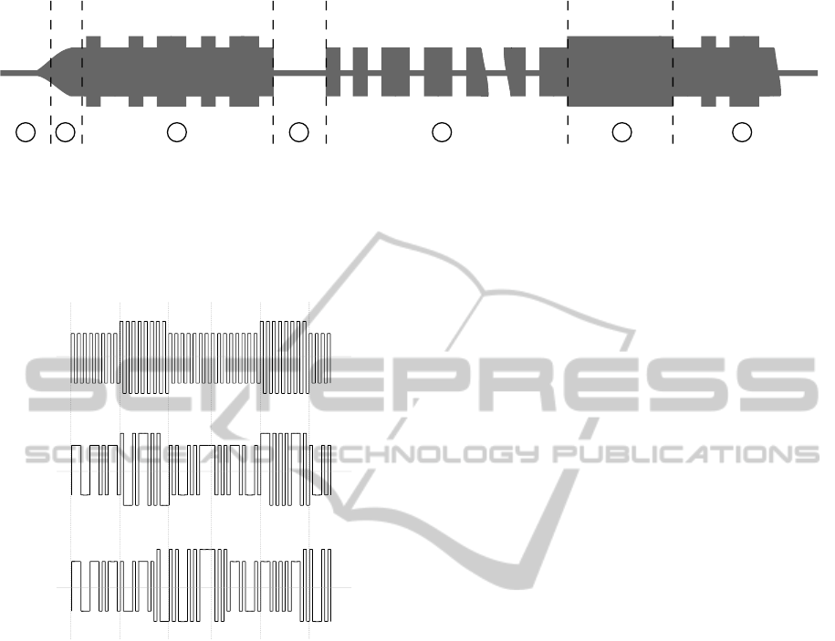
2 31 4 5 6 7
Figure 2: ATA5577C modes of operation (Atmel Corporation, 2014). 1 – The tag enters the RF field, internal capacitor is
being charged. 2 – Power up and initial delay. The tag should enter the regular-read mode in about 3 ms after entering the RF
field. 3 – Normal read mode, data encoded with Manchester and ASK modulation. 4 – Start gap; switch from the normal read
mode to the write mode, typically 64 – 400 µs. In the write mode, the receiver damping is enabled by default. 5 – Sequence
of operational code, lock bit, block data and address is sent by an on-off modulation using the write gaps of 64 - 160 µs. 6
– Programming stage; writing data to the internal EEPROM. 7 – After programming, the tag returns back to the normal read
mode.
A
B
C
Figure 3: Frequency alternation - (a) Normal modulation
with the fixed carrier frequency; (b) Modulation based on
the tag’s external timing. As can be seen, the amplitude
changes according the timing derived independently from
the carrier frequency; (c) Modulation based on the carrier
frequency timing. The length of the damping periods is
based on the number of carrier cycles (eight in this exam-
ple).
69 ms (Atmel Corporation, 2014). What is important
to mention, is that if any field gap occurs during the
initialization phase, the tag will restart the initializing
sequence from the beginning. After the initialization
phase, the tag enters the regular-read mode.
The programmable tags have (in contrast to the
read only tags) additional modes for programming
the tag content and setting its correct operation. The
switch to this mode is usually triggered by inserting
additional gaps. The initial gap and the data itself are
transmitted by interrupting the RF field with the short
field gaps (on-off keying of the carrier signal). The
time between two succeeding gaps encodes the indi-
vidual bits. The illustration of the operation modes of
the ATA5577C is depicted in Figure 2.
The clones and emulators based on the MCU of-
ten ignore the RF interruption and continue in the se-
quence of the data bits as if nothing happened. If
the tag has an external power supply, interrupting the
RF field does not trigger the reset. Based on the
type of clock source, the output can be still synchro-
nized with the carrier (the clones using the carrier fre-
quency as the clock source), or can be out of phase
and out of synchronization (the ones based on the in-
ternal clock). The Figure 4 shows an example of out
of synchronization data from the fake tag. One would
expect that the tag will start sending the synchroniza-
tion header just after entering the RF field. Instead of
this, we can see some bits from the data part. This
is common behaviour of externally powered fake tags
(emulators).
3.3 Timing Measurement
The only function (operating mode) of the genuine
read only tags is to send the 64 bit data sequence and
repeat it continuously until the power goes off. The
programmable tags operate in regular-read mode in
the same fashion. Based on the configuration, they
start transmission with the first block and first bit, and
continue up to the last configured block and its last
bit. Additionally, the E55xx tag can be programmed
to use a sequence terminator which is inserted in front
of the first block. The time of recovery (between the
repetition of the sequence) can indicate the additional
processing in the tag. The longer recovery periods can
mark the fake tags with the MCU.
4 CLONED TAG DETECTOR
The proposed solution of the clone detection system is
implemented in the RFID reader based on Atmel AT-
mega168 microcontroller. The RF part of the reader is
EM410xRFIDClonedCardDetectionSystem
79
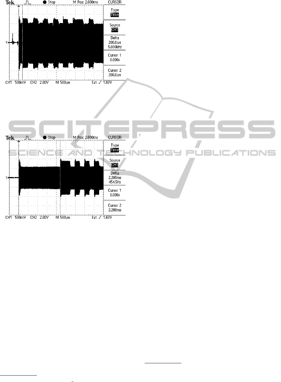
Figure 4: Example of fake tag timing. The sequence is
out of synchronization with the reader. Moreover, the se-
quence has not the expected synchronisation bits despite the
RF field was just turned on (compare to Figure 1). This is
the typical behaviour of self-powered and self-clocked fake
tags.
Figure 5: Example of fake tag timing. Long starting delay
(2200 µs) typical for unlocked E55xx programmable tags.
based on the Proximity Card Reader / Cloner project
1
.
The carrier signal is either generated by an 8MHz
external oscillator and divided by a counter to the
125 kHz signal or by an internal counter of the At-
mel microcontroller. The RF front end consists of a
tuned LC resonator and an AM peak detector with a
series of low pass and band pass filters to extract the
12.5 kHz and 15.6 kHz signals.
In the basic mode, the firmware of the microcon-
troller samples the input from the filtered output and
stores the bits it in the main memory. If the initial
header bits are detected, the firmware parses the fol-
lowing bits, checks the parity and prints the card data.
The extended mode enables the additional tests
for fake/cloned tags as described in Section 3. The
controller is able to modulate the carrier or change its
frequency as necessary. The following tests are per-
1
http://proxclone.com/reader cloner.html
formed sequentially:
• The RF field with 125 kHz carrier is periodi-
cally switched on/off and the t
i
, time between the
start of RF field and the first detected modulation
change, is measured. Additionally, received bit
sequence is checked whether it starts with the ex-
pected nine synchronisation bits or contains other
arbitrary sequence.
• During the read phase, the RF field is interrupted
for 200 µs and the response is monitored. If the
write damping is detected, it is evaluated as a clear
indication of the programmable tag. Even if the
write damping is not detected
2
, the reader tries to
send the reader command sequences and checks
the responses.
• Finally, the reader shifts the carrier frequency and
checks whether the timing of the modulation pro-
duced by the tag matches the RF field clocks. The
tolerance was set to 20 % of the expected timing.
Figure 3 provides an illustration of the possible
outcomes. The genuine tag should derive its tim-
ing only on the RF field cycles.
These tests are performed in the given order to
shorten the time necessary to read the tag and de-
cide whether the tag is genuine or not. The standard
reader will send the tag data as soon as the block is
transferred and the parity checksums are valid. Mean-
while, our reader has to perform additional checks and
therefore holds the read data until is able to indicate
whether the tag is genuine or seems to be a clone or
an emulator.
From a practical point of view (when the RFID
system is used, e.g., as an entry system) the users ex-
perience is negatively affected by the longer delay of
the RFID card reader performing the additional secu-
rity tasks. Therefore, the firmware starts with the tests
that do not require additional time (e.g. measuring the
initial delay) and continue with those requiring more
scanning time.
As the detection based on the measuring of the
initial delay proved quite reliable, we are able to de-
tect most of the clones immediately after finishing
this test, even if the tag was not in the range of the
reader for enough time to perform all of the remain-
ing checks mentioned above. The goal is that the user
shall not notice any additional delays when using the
RFID tag in, e.g., entry system.
2
The newer rewritable tags with configurable analogue
front end (e.g. ATA5577C) provide the possibility to disable
the write damping.
PECCS2015-5thInternationalConferenceonPervasiveandEmbeddedComputingandCommunicationSystems
80

Figure 6: Experimental reader based on ATMega168 used
during the experiments.
4.1 Results
The experiments were performed on a set of genuine
tags (mainly university ISICs with RFID chips, home
security system entry cards and RFID tags from the
consumer products), rewritable tags (thin card tags
and key fobs available from eBay sellers) and emu-
lators (both passive and active ones).
The average time t
i
between the start of the RF
field and the first detected modulation change of the
genuine tags (n = 22) was 309 µs (s = 101 µs). The
value n refers to the total number of the examined
(different) tags. In contrast, the programmable tags
compatible with E5550 (n = 10) had an average t
i
of
2.322 ms (s = 0.06 ms). The tag emulators (n = 5)
based on the construction described in (Dowty, 2010)
had an average t
i
1.036 ms (s = 0.219 ms). This time
is significantly influenced by the design of the coil
and used microcontroller (especially if the low-power
version or standard is used). Finally, the active tag
emulator (Krumnikl, 2007) had an average t
i
delay
180 µs (s = 82 µs). These delays were not caused
by the MCU itself, but just correspond to the trans-
mitted sequence. As it is powered externally, it does
not need any time to settle down in the RF field (see
Figure 4). The statistical evaluation showed that there
is a significant difference between the groups of gen-
uine and fake tags (ANOVA, p < 0.001). Overall, the
initial delay is the most significant indicator showing
that the tag is not genuine. The classification based
on the threshold of the initial delay was used in the
implemented firmware.
The unlocked programmable tags can be easily
detected by interrupting the RF field. All available
programmable tags (n = 10) responded to the initial
gap by damping the RF field. Moreover, it is pos-
sible to program the reader in such way that if it de-
tects the programmable tag, it will consider it as a fake
card and erase (rewrite) its content. In that way you
can actively fight with the clones by disabling them.
Table 1: Summary of the detecting capabilities of each in-
troduced approaches. (Empty bullet corresponds to no de-
tectable anomalies, full bullet for evident anomaly.)
Detected Anomalies
Tags Freq. alter. Timing sync. RF int.
EM4100 m m m
ATA5557 m l l
MCU ext. m w m
MCU int. l l m
The firmware contains all necessary routines for the
reader-to-tag communication, so it can act in other
scenarios as a cloner or RFID tag programmer.
By shifting the carrier frequency we were able
to detect the active emulators. Only these emulators
maintained the 125 kHz timing even if the carrier sig-
nal was transmitted on a different frequency. How-
ever, we have to admit that we had only one device
for the experiments. Thus we can not make any sort
of conclusions if other emulators would behave in the
same manner. The easily readable summary for each
type of tag can be found in Table 1.
5 SUMMARY
The experiments performed with the proposed RFID
reader with additional clone detection functionality
have shown that it is possible to reliably detect the
majority of publicly available fake tags and emula-
tors. However, as the EM410x tags do not provide any
form of cryptographic features, it is possible to make
the identical copies. Our experiments have shown that
there are always some minor differences that can be
detected; however there are no insurmountable ob-
stacles to construct a passive device indistinguishable
from the original tag (but so far there are no publicly
available constructions designed this way). Closest
to this goal are the passive tags based on the micro-
controller or FPGA devices. As there are no readers
precisely checking the timing and all tags comply to
the standard, the manufacturers are not obligated to
maintain specific parameters we have monitored.
Despite we introduced potentially usable solution
for detecting the counterfeits, the EM410x tags shall
not to be considered as secure.
The deployment of our solution can be recom-
mended in the situations where the replacement of all
cards and readers with more secure smart RFID tags
is not possible (mainly due to the costs or difficulties
with the replacement of all tags among users).
In the future work we would like to focus on the
development of the similar fake detecting reader for
the smart tags. Specific delays can help identifying
EM410xRFIDClonedCardDetectionSystem
81

the tags and counterfeits. However, more advanced
techniques will be necessary since the smart tags em-
ploy cryptographic routines and other features. The
detectable timing issues should also occur when a re-
lay attack is performed.
The schematic and firmware of the construction
presented in this paper is available upon request.
ACKNOWLEDGEMENTS
This work was partially supported by the grant of SGS
No. SP2014/170, V
ˇ
SB - Technical University of Os-
trava, Czech Republic.
REFERENCES
Atmel Corporation (2014). ATA5577C Read/Write LF
RFID IDIC 100 to 150 khz. Technical Datasheet, rev.
9187HRFID07/14.
Blass, E.-O., Elkhiyaoui, K., and Molva, R. (2011). Tracker
: security and privacy for RFID-based supply chains.
In NDSS 2011, 18th Annual Network and Distributed
System Security Symposium, 6-9 February 2011, San
Diego, CA, USA, San Diego, UNITED STATES.
de Koning Gans, G., Hoepman, J.-H., and Garcia, F. (2008).
A practical attack on the MIFARE Classic. In Gri-
maud, G. and Standaert, F.-X., editors, Smart Card
Research and Advanced Applications, volume 5189 of
Lecture Notes in Computer Science, pages 267–282.
Springer Berlin Heidelberg.
Dowty, M. (2010). Software-only implementation
of a passive low-frequency RFID tag, using an
AVR microcontroller. Source code. Available at
http://svn.navi.cx/misc/trunk/avrfid/avrfid.S.
EM Microelectronic-Marin SA (2004). EM4100 read only
contactless identification device. Technical Datasheet.
Garcia, F., de Koning Gans, G., Verdult, R., and Meriac, M.
(2012). Dismantling iclass and iclass elite. In Foresti,
S., Yung, M., and Martinelli, F., editors, Computer Se-
curity ESORICS 2012, volume 7459 of Lecture Notes
in Computer Science, pages 697–715. Springer Berlin
Heidelberg.
Hancke, G. (2005). A practical relay attack on ISO 14443
proximity cards. Technical report.
Hancke, G. (2006). Practical attacks on proximity identifi-
cation systems. In Security and Privacy, 2006 IEEE
Symposium on, pages 6 pp.–333.
Issovits, W. and Hutter, M. (2011). Weaknesses of
the ISO/IEC 14443 protocol regarding relay attacks.
In RFID-Technologies and Applications (RFID-TA),
2011 IEEE International Conference on, pages 335–
342.
Koh, R., Schuster, E. W., Chackrabarti, I., and Bellman,
A. (2003). Securing the pharmaceutical supply chain.
White Paper, Auto-ID Labs, Massachusetts Institute of
Technology, pages 1–19.
Koscher, K., Juels, A., Brajkovic, V., and Kohno, T.
(2009). Epc RFID tag security weaknesses and de-
fenses: Passport cards, enhanced drivers licenses, and
beyond. In Proceedings of the 16th ACM Conference
on Computer and Communications Security, CCS ’09,
pages 33–42, New York, NY, USA. ACM.
Krumnikl, M. (2007). Unique (EM4001) RFID emulator.
Technical report, Department of Computer Science.
V
ˇ
SB - Technical University of Ostrava.
Lehtonen, M., Ostojic, D., Ilic, A., and Michahelles, F.
(2009). Securing RFID systems by detecting tag
cloning. In Tokuda, H., Beigl, M., Friday, A., Brush,
A., and Tobe, Y., editors, Pervasive Computing, vol-
ume 5538 of Lecture Notes in Computer Science,
pages 291–308. Springer Berlin Heidelberg.
Mackey, T. K. and Liang, B. A. (2011). The global counter-
feit drug trade: patient safety and public health risks.
Journal of pharmaceutical sciences, 100(11):4571–
4579.
Mitrokotsa, A., Rieback, M., and Tanenbaum, A. (2010).
Classifying RFID attacks and defenses. Information
Systems Frontiers, 12(5):491–505.
Oswald, D. and Paar, C. (2011). Breaking Mifare DESFire
MF3ICD40: Power analysis and templates in the real
world. In Preneel, B. and Takagi, T., editors, Cryp-
tographic Hardware and Embedded Systems CHES
2011, volume 6917 of Lecture Notes in Computer Sci-
ence, pages 207–222. Springer Berlin Heidelberg.
Verdult, R., Garcia, F. D., and Balasch, J. (2012). Gone in
360 seconds: Hijacking with Hitag2. In Proceedings
of the 21st USENIX Conference on Security Sympo-
sium, Security’12, pages 37–37, Berkeley, CA, USA.
USENIX Association.
Zanetti, D., Capkun, S., and Juels, A. (2013). Tailing RFID
tags for clone detection. In NDSS.
PECCS2015-5thInternationalConferenceonPervasiveandEmbeddedComputingandCommunicationSystems
82
