
A Novel Approach using Alloy in
Domain-specific Language Engineering
Rodrigo M. L. M. Moreira and Ana C. R. Paiva
INESC TEC and Department of Informatics Engineering, Faculty of Engineering of the University of Porto, Porto, Portugal
Keywords:
Domain-specific Language, DSL Engineering, DSL Development, GUI Modeling, GUI Testing.
Abstract:
Modeling and building software systems for a given specific domain is a complex task. Domain-Specific
Languages (DSLs) have been increasingly gaining attention because they are developed to cope with particu-
larities of specific domains. However, DSL development consists in a set of tasks to be performed and some
can be error-prone. Identifying the correct set of elements within a DSL and their constraints can be very
demanding. Alloy is a popular lightweight intuitive formal language with a simple notation that is easy to read
and write. When models of a DSL are specified using Alloy, it becomes possible to generate instances that
should represent valid models. So, this paper presents a generic innovative methodology using Alloy in DSL
engineering, in order to find and tune language constraints in a systematic way. It also presents an empirical
study illustrating the applicability of the proposed methodology.
1 INTRODUCTION
Domain-specific languages (DSLs) are languages
custom-made to a specific application domain. The
demand for domain-specific languages is led by the
need to define specific domain features within a
given context/domain, accomplishing the desire to
communicate them using paradigms familiar to do-
main experts. DSLs can be applied to several do-
mains/contexts, such as (Voelter et al., 2013): archi-
tecture – to describe components, interfaces and mes-
sages of software systems; requirements engineering
– to provide a checkable comprehensive description
of requirements and artifact traceability; product line
engineering (PLE) – PLE is about expressing, man-
aging and binding variability between a set of related
products, therefore making DSLs a great tool to cap-
ture the variability; among others.
DSL development is a complex task that requires
domain knowledge and language development skills.
Further, it can be error-prone and normally time con-
suming. However, current tools simplify technical as-
pects in the development but lack support in terms
of imposing good language design and implementa-
tion. DSL development is an iterative process that
is comprised by 5 major activities (Strembeck and
Zdun, 2009): (1) Definition of the Language Core
Model with the language elements and their relations;
(2) Add constraints (when required) to restrict the
language functionalities and therefore behavior (Lan-
guage Model Constraints); (3) Specify the Syntax of
the language to describe how the elements are rep-
resented; (4) Describe the dynamic Behavior of the
elements of the language, i.e., how such elements per-
form and interact; (5) Integrate the DSL within a tool
to support the construction of models (Platform In-
tegration). In this paper we will focus on activities
number 1, 2 and 4. We provide a methodology using
Alloy (Jackson, 2011) to support previous activities.
Alloy is a lightweight, simple yet powerful formal
language that supports structural and behavioral mod-
eling. It can be used at early stages of software de-
velopment allowing to discover the correct software
abstractions. Moreover, it allows to express struc-
tural and behavior constraints. The main benefit of
using Alloy during DSL development is its capabil-
ity to support an iterative process to define and tune
language constraints. This process terminates when
the constraints necessary to ensure the construction
of well-formed model are found. Alloy is supported
by the Alloy Analyzer tool, a friendly SAT (satisfa-
bility) based tool that enables automatic model V&V
(verification and validation). When models are spec-
ified using Alloy, it becomes possible to generate in-
stances that should represent valid models (according
to specific rules), and thus analyzing them in order to
find/define and tune language constraints.
Alloy, unlike other modeling languages like UML,
157
M. L. M. Moreira R. and C. R. Paiva A..
A Novel Approach using Alloy in Domain-specific Language Engineering.
DOI: 10.5220/0005228101570164
In Proceedings of the 3rd International Conference on Model-Driven Engineering and Software Development (MODELSWARD-2015), pages 157-164
ISBN: 978-989-758-083-3
Copyright
c
2015 SCITEPRESS (Science and Technology Publications, Lda.)

Z and VDM, is more abstract with a considerable ex-
pressive power. It is also supported by a tool (SAT
solver), which allows the model to search exhaus-
tively to a certain limit (bound). Support tools from
the latter mentioned modeling notations, do not pro-
vide simple, precise, concise and iterative ways to
generate instances of the models, neither provide a
way to graphically visualize those instances as Alloy
Analyzer tool does.
The contributions of this paper include:
– a novel approach using Alloy in DSL engineering;
– a detailed step by step description (guidance) of a
method to find and tune DSL language constraints
using Alloy;
– an empirical study to support the proposed
methodology.
The remainder of this paper is organized as fol-
lows. Section 2 provides insight regarding model-
ing notations that can be applied in DSL engineering.
Section 3 describes Alloy in further depth and Section
4 presents the methodology describing how to use Al-
loy in DSL engineering. Section 4 presents an empir-
ical evaluation concerning the proposed methodology
by means of a case study. Finally, Section 5 draws
conclusions.
2 BACKGROUND
The focus of this section is directed towards the back-
ground on modeling languages with which it is possi-
ble to build software models. A set of frameworks for
language implementation are also covered.
UML and OCL
The Unified Modeling Language (UML) is a popu-
lar and widely used specification that allows to model
structure, behavior, architecture, business processes
and data structures (Rumbaugh et al., 2004). UML
uses diagrams to describe the models. A UML dia-
gram does not provide all relevant aspects of a spec-
ification. There is a need to describe additional con-
straints concerning the objects featured in a model.
These constraints are typically described in a natu-
ral language. The Object Constraint Language (OCL)
is the constraint language of UML. It is a precise,
declarative language that is simple to understand for
people who are not mathematicians or computer sci-
entists. It does not feature any mathematical sym-
bols, but maintains mathematical rigor in its definition
(Warmer and Kleppe, 2003).
The graphical notation of UML has no equivalent
in textual style. Therefore, only with OCL is possible
to specify additional constraints of the model in text.
OCL can be used to specify restrictions such as invari-
ants, preconditions, postconditions, among others.
OCL is often referred as a “side-effects-free” lan-
guage since the state of the system does not change
due to an OCL expression. When an expression is
evaluated, it returns a value, without affecting the
model.
Z
Z is a formal specification language based on
Zermelo-Fraenkel set theory and first order predicate
logic. It originated in early 1980s at the Program-
ming Research Group at Oxford University. Due to its
mathematical specifications that guarantee precision,
it is possible to identify inconsistencies and gaps in
the specification. In order to demonstrate if the soft-
ware implementation matches the specification, Z al-
lows to use theorem provers (O’Regan, 2013).
The Z notation is based upon set theory and math-
ematical logic. The set theory contains standard set
operators, set comprehensions, Cartesian products,
and power sets. The mathematical logic is a first-order
predicate calculus. Combined, they form a mathemat-
ical language that is easy to learn and to apply.
Models can be developed using mathematical data
types, which are able to identify the desired behavior
of a system. The model can be refined until the de-
sired purpose of the system is fulfilled.
VDM
The Vienna Development Method (VDM) was origi-
nally developed at the IBM laboratories in Vienna in
the 1970’s (Jones, 2001). Thus, it is one of the longest
established formal method. The method comprises
a specification language and an approach to refining
specifications into code. Several principles and ideas
regarding logic-based specification were originated in
VDM.
A VDM specification can be seen as a state ma-
chine containing a set of states and a collection of
operations. The states are given by a declaration
and auxiliary declarations to introduce any composite
types that it uses (Jackson, 2011). Each declaration
can have an invariant. The operations define how the
states evolve.
MODELSWARD2015-3rdInternationalConferenceonModel-DrivenEngineeringandSoftwareDevelopment
158

Spoofax
Spoofax (Kats and Visser, 2010) is a language work-
bench for developing textual DSLs, that is built on
top of the Eclipse Framework. Spoofax is comprised
by a set of tools that support grammar definition and
DSL transformation to the desired targeted language.
Grammars are specified using a syntax definition for-
malism (SDF). Another important part is the Stratego
transformation language, which allows to describe the
semantics of the language (Bravenboer et al., 2008).
Spoofax uses the Eclipse IDE Meta-tooling Plat-
form IMP. By doing so, it provides several benefits
such as code outline, code completion, syntax high-
lighting, error checking and also offers the possibil-
ity to export the complete project as a stand-alone
Eclipse plugin. However, as indicated in (Schmitt
et al., 2014), Spoofax/IMP lacks stability.
xText
xText is a language development framework to assist
the creation of DSLs and programming languages. It
includes a parser, a code generator/interpreter, and
facilitates Eclipse IDE integration (Bettini, 2013).
DSLs are specified using xText’s grammar language.
In order to validate a DSL, validators are required
to be implemented to perform additional constraint
checks (Bettini, 2013).
3 ALLOY
Alloy is a declarative specification language devel-
oped by the Design Group at MIT since 1997. It
is based on first-order logic, for expressing complex
structural constraints and behavior (Jackson, 2011).
It is designed to accurately describe the specification
and the modeling of a system. Alloy is appropriate
for early stages of software development, allowing to
discover the correct software abstractions. Alloy is
based on relational logic that combines the quantifiers
of first order logic with the operators of the relational
calculus.
Alloy has simple but powerful syntax that is easy
to read and write. Alloy is supported by a verification
tool called Alloy Analyzer, which can be used to au-
tomatically analyze the alloy specifications. This tool
performs bounded verification using SAT (satisfiabil-
ity) solvers to answer verification queries.
An Alloy specification (model) needs to be built
textually. After building the alloy model by the ana-
lyzer, the model can be represented by the graphical
part and the textual part (He, 2006). An Alloy speci-
fication is defined by a module, which includes a set
of imports with paragraphs. A paragraph can be a
signature, a fact, a predicate, a function, an assertion
or a command. A signature introduces a typed set of
atoms and may have fields. Facts are constraints on
relations that always hold. A predicate is a named
constraint with zero or more arguments. Functions
define reusable expressions. Assertions are properties
that must hold from facts of the model. Commands
are instructions that allow to perform check and run
analysis. Run instructs the analyzer to search for an
instance of a given predicate. Check instructs the ana-
lyzer to search for a counterexample of a given asser-
tion.
3.1 Comparison with Other Approaches
UML is a popular modeling notation that has been
widely accepted. UML models do not have formal
semantics and their constraints must be added using
OCL. In terms of syntax, Alloy is compatible with
OCL/UML. In addition, Alloy and OCL have formal
syntax and semantics. However, Alloy has simpler
syntax and semantics (He, 2006). OCL is declara-
tive and operational, whereas Alloy is fully declara-
tive (He, 2006).
Alloy was based in the Z specification language.
Like Z, Alloy is suitable for describing structural
properties of systems. Yet, Alloy was designed with
the goal of making specifications automatically ana-
lyzable (Frias et al., 2005). Alloy Analyzer automat-
ically generates instances of the model, without the
need to write additional code for verification and val-
idation of the model (unlike Spoofax and xText). Fur-
thermore, it allows to exercise the model enabling a
more elaborate and quickly graphical analysis.
4 METHODOLOGY
As introduced earlier, our focus relies on the usage
of Alloy in DSL Engineering. Given a domain that
requires a DSL to be created for that specific purpose,
we propose a total of five steps that domain experts
should comply with, in order to design the DSL using
Alloy. One important aspect to mention is that this is
always an iterative process. This process should be
concluded, only after defining, tuning and analyzing
the expected behavior of the DSL language elements.
The proposed methodology is illustrated in Figure 1.
The methodology describes the following steps:
• Step 1. Specification of DSL Elements – The
first step is the definition of the structure of the
ANovelApproachusingAlloyinDomain-specificLanguageEngineering
159
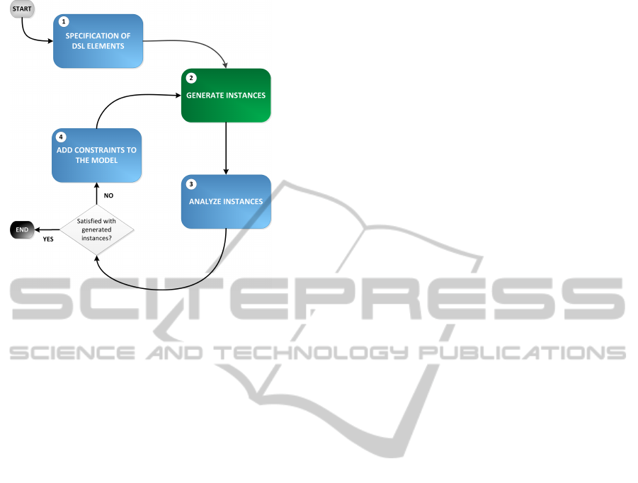
Figure 1: Methodology for the usage of Alloy in finding
language constraints for DSL Engineering.
DSL with its elements. These elements are de-
fined as signatures in Alloy;
• Steps 2 and 3. Generate and Analyze Instances
– The Alloy model is executed through the Al-
loy Analyzer tool to generate instances that should
correspond to valid models written in the DSL be-
ing defined. To generate those instances, the de-
veloper should write run commands with proper
bounds, for example, “run {} for 3” means that
the instances generated will have a maximum of 3
elements of each signature. Typically, in the first
iteration it is not necessary to define high bounds,
since issues will be found in small instances. In
the forthcoming iterations there will be the need to
increase the bound of runs in order to keep aiming
towards the growth of confidence in the quality of
the model;
• Step 4. Add Constraints to the Model – If prob-
lems are identified within instances generated in
the previous step, constraints should be added to
the model.
• Tune the Model by Repeating Steps 4, 2 and 3
– these steps should be repeated until no problems
are found in the generated instances of the model.
This methodology allows finding, tuning and
graphically analyze instances from a DSL model. Do-
main experts should use this methodology to facilitate
the reasoning about the constraints that are ought to
be specified, in order to fulfill language goals defined
prior. In the next section we present a case study to
support the proposed methodology.
5 EMPIRICAL EVALUATION
To assess the applicability and real-world relevance
of our method, we conducted a case study according
to Runeson and H
¨
ost guidelines (Runeson and H
¨
ost,
2009). Our evaluation addresses the following
research question:
RQ. Can Alloy be useful in assisting to discover con-
straints of a DSL, and therefore systematize the pro-
cess of building a DSL?
5.1 Experimental Object
Pattern Based GUI Testing (PBGT) is a new model-
based GUI testing paradigm that aims to promote
reuse of GUI testing strategies (Moreira et al., 2013).
PBGT requires a model describing the testing goals
from which test cases will be generated and executed
on the GUI under test. The DSL defined in this paper
(PARADIGM) will allow building such models.
The focus of this study is on the development of
PARADIGM language from scratch to be used in the
context of PBGT. PARADIGM is comprised by el-
ements and connectors. PARADIGM is defined by
four types of elements: Init, End, Structural and Be-
havioral. A model written in PARADIGM can be
structured in different levels of abstraction (i.e. can
be defined hierarchically) (Moreira and Paiva, 2014).
Forms and Groups are structural elements. A Form al-
ways starts with an Init and End element and embod-
ies a model (or sub-model). A Group element is used
to hold elements that may be executed in any order.
Behavioral elements represent the UI Test Patterns
that define strategies for testing the UI Patterns (Mor-
eira et al., 2013). PARADIGM connectors are based
on ConcurTaskTrees (CTT) (Patern
`
o et al., 1997) and
establish relations among elements.
5.2 Experimental Setup
To start the experiment we installed the Alloy Ana-
lyzer tool and then started the DSL development pro-
cess, by defining the elements of the language and fol-
lowing with the generation of the model instances and
the other steps described in the methodology. As al-
ready mentioned, this is an iterative process that ends
when the developer is comfortable with the instances
generated and all constraints are found.
5.3 Results and Findings
We applied the methodology proposed earlier and we
obtained a set of results and findings that will be de-
MODELSWARD2015-3rdInternationalConferenceonModel-DrivenEngineeringandSoftwareDevelopment
160
scribed below.
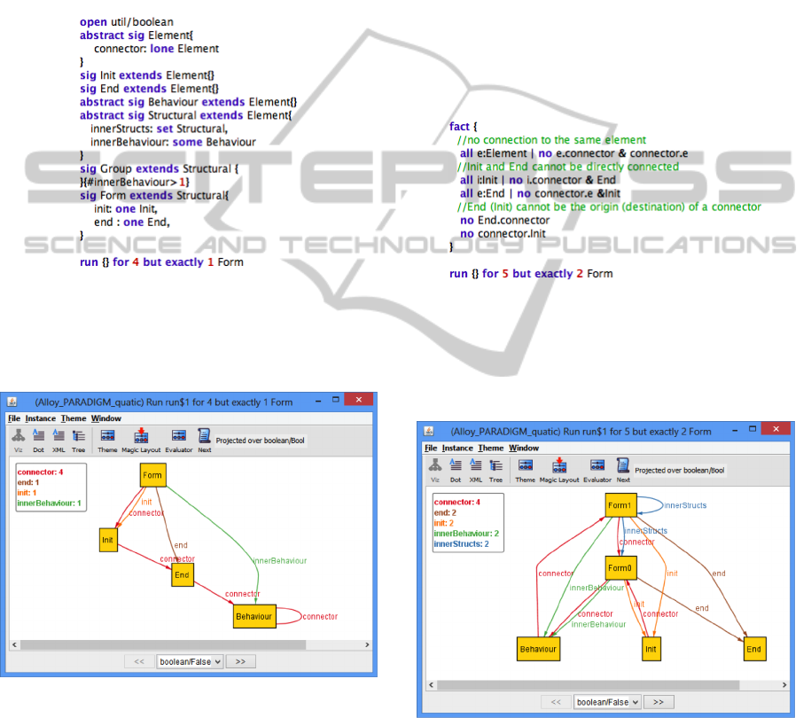
First Iteration
In our first iteration, we created an Alloy model for
PARADIGM. The model is illustrated in Figure 2.
The command “run {} for 4 but exactly 1 Form”
means that instances generated will have at most 4
elements of each signature but exactly one instance of
the Form signature.
Figure 2: PARADIGM Alloy Model – First iteration.
Then, we executed this model (from Figure 2) and
analyzed the generated instances. One of those in-
stances is displayed in Figure 3.
Figure 3: Generated instance of the model from Figure 2.
First Iteration Issues
The instance (Figure 3) faces some problems. There
is a link from a Form element to the Init element (the
Init element is an internal element inside the Form).
This should not happen since these elements belong
to different hierarchical levels. The other issue is re-
lated with links from an element to itself. This must
not happen. Yet, in the generated instance we can
see that there is a connector from Behaviour to Be-
haviour. Also, the Init element should always be the
first element in the model and the End element should
be the last one. Again, we obtained a link from the
Init to the End and from the End to the Behaviour el-
ement. This is not correct. Further, the Init element
should not link directly to the End element.
Second Iteration
In the pursuit of finding the expected behavior of
PARADIGM language elements, we proceeded for
the second iteration. We added new statements (con-
straints) in the model. These constraints are displayed
in Figure 4.
Figure 4: New added constraints to the PARADIGM Alloy
Model (from Figure 2) – Second iteration.
One of the generated instances of the model (from
Figure 2 including the new statements from Figure 4)
is illustrated in Figure 5.
Figure 5: Generated instance of the model from Figure 2
including the new statements from Figure 4.
Second Iteration Issues
In this iteration we still have some problems. The in-
nerStructs relation cannot allow one element to “live”
inside itself (we are obtaining Form1 with another
Form1 inside). Moreover, we cannot have elements
ANovelApproachusingAlloyinDomain-specificLanguageEngineering
161
from different levels (depth levels) connected. How-
ever, as can be seen, we have Behaviour connect-
ing Form1. Form1 has Init and End elements inside.
Form0 has the same Init and End elements inside. Yet,
elements Init and End cannot belong to more than one
Form (level). Each level (Form) must have an Init and
an End element but they cannot belong to more than
one Form (level).
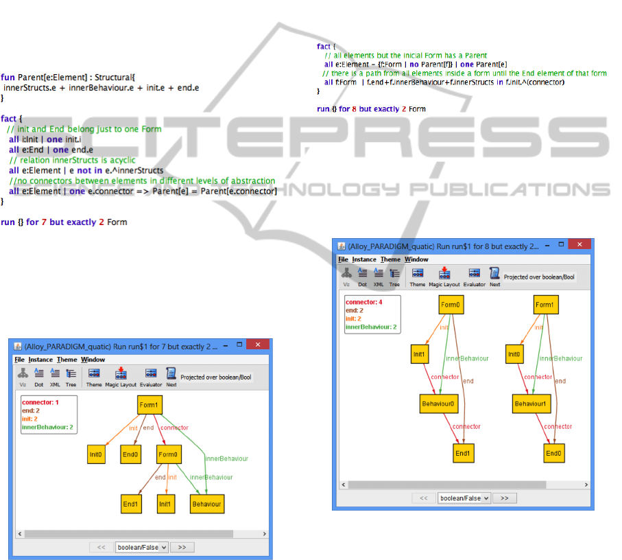
Third Iteration
We continuously increased the number of constraints.
The added constraints for this third iteration are dis-
played in Figure 6.
Figure 6: New added constraints to the PARADIGM Alloy
Model – Third iteration.
The obtained instance from executing the model
(including its previous iterations) with the new con-
straints from Figure 6, is illustrated in Figure 7.
Figure 7: Generated instance of the model including the
new statements from Figure 6.
Third Iteration Issues
By analyzing the executed model, we became aware
of the following problems. The Behaviour element is
inside Form0 and Form1 (it belongs to two different
abstraction levels, i.e, it has two parents). This is not
allowed. In addition, PBGT approach generates test
cases from PARADIGM models and for that it cal-
culates all the paths from Init to End elements. This
means that the elements inside PARADIGM models
must be connected. Inside Form1 there are not con-
nectors that link Init0 to Form0 and End0. Therefore,
there is no path. We need to ensure that there must be
connectors from Init to the End elements.
Fourth Iteration
We added further constraints to the model (Figure 8).
Figure 8: New added constraints to the PARADIGM Alloy
Model – Fourth iteration.
Then, we analyzed the generated instances by ex-
ecuting the model (including its previous iterations)
with the new constraints from Figure 8). One of those
instances is displayed in Figure 9.
Figure 9: Generated instance of the model including the
new statements from Figure 8.
Fourth Iteration Issues
In this iteration we only encountered one problem.
This instance shows two separated models and thus,
we need another constraint ensuring that there is only
one Form without parent, i.e., the main model.
MODELSWARD2015-3rdInternationalConferenceonModel-DrivenEngineeringandSoftwareDevelopment
162
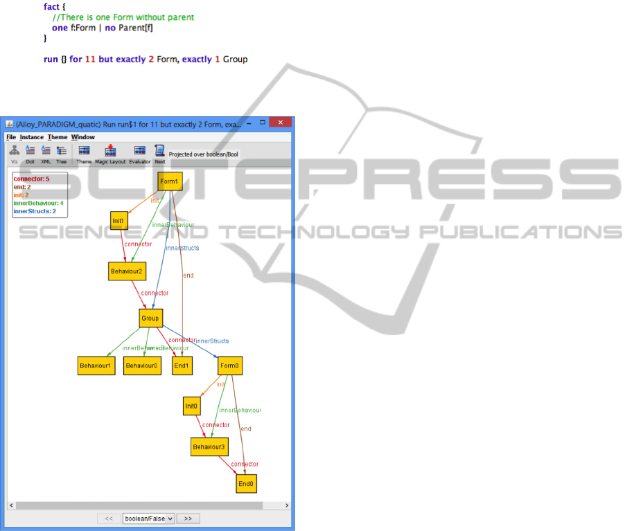
Fifth Iteration
In this iteration we added the constraint to ensure only
one Form with no parent and increase the bound of
the run command (Figure 10) to check if the generated
model instances were valid, i.e., correspond to correct
models written in PARADIGM.
Figure 10: New added constraints to the PARADIGM Alloy
Model – Fifth iteration.
Figure 11: Generated instance of the model including the
new statements from Figure 10.
Fifth Iteration Issues
In this iteration, for the instance (Figure 11), we did
not found any issues. Therefore, we have encountered
all our restrictions and we concluded the study execu-
tion.
Final Constraints
After five iterations, we were satisfied with the
obtained results. Therefore, the final language
constraints for PARADIGM were:
LC1: A Connector cannot connect an element to it-
self;
LC2: A Connector cannot have Init as destination
neither End as source;
LC3: An Init element cannot connect directly to an
End element;
LC4: Two elements cannot be connected more than
once by connectors of the same type;
LC5: Two Elements can only be connected if they
belong to the same Structural Element (Model; Form;
Group);
LC6: Elements inside a Form (but not inside Groups
of that Form) cannot be loose, i.e., for all elements
within a Form, there is at least one path from the Init
to the End that traverses that element;
LC7: The model must be a Form without a parent.
5.4 Threats to Validity
A threat to the external validity of our evaluation is
related with the generalization of the results to other
DSL languages. We recognize that more experimental
objects could be evaluated in order to support our re-
sults even further. However, the selected experimen-
tal object is representative to demonstrate, assess and
validate our methodology.
5.5 Discussion
We were able to build from scratch, a specification
for the PARADIGM DSL, according to the proposed
methodology. Alloy has proved to be helpful in find-
ing and tuning the language constraints, until we
achieved satisfaction with the results. In addition, it
assisted in discover issues with the specification and
we were able to quickly progress towards correcting
the issues and progressing further towards our goal.
Alloy was designed with the goal of making spec-
ifications automatically analyzable, and this provides
a significant advantage when considering using Alloy
to find language constraints, in the topic of DSL en-
gineering. In a way, everything written in Alloy is
executable.
Another aspect is that the Alloy Analyzer tool
does an exhaustive check within the defined limit.
Therefore, we have the assurance that in this partic-
ular domain, the specification is correct. Alloy also
provides a better understanding in finding the desired
behavior of the DSL language elements. The latter
can be observed throughout the several iterations of
our study.
ANovelApproachusingAlloyinDomain-specificLanguageEngineering
163

These results have boosted our confidence in dis-
covering the necessary constraints for PARADIGM.
We feel that we are now able to implement and incor-
porate them in a modeling environment (a tool that
allows to create PARADIGM models), and thus en-
suring that models are created correctly.
6 CONCLUSIONS
This paper introduced a novel approach using Alloy in
DSL engineering, in order to find and tune language
constraints. Thus, we provide an empirical study –
the development of a DSL called PARADIGM for the
PBGT domain – to support our methodology. Results
indicate that it is feasible to use Alloy to define the
language elements and its relations and also to tune
language constraints. Also, to the best of our knowl-
edge, Alloy has never been used to assist the creation
of DSLs in the context of GUI modeling.
One of the benefits of using Alloy is due to the
simplicity in write specifications and the capability
of executing these specifications (in Alloy Analyzer
Tool) in order to be analyzed in further depth in a
graphical manner.
ACKNOWLEDGEMENTS
This work is financed by the ERDF - European Re-
gional Development Fund through the COMPETE
Programme (operational programme for competi-
tiveness) and by National Funds through the FCT
- Fundac¸
˜
ao para a Ci
ˆ
encia e a Tecnologia (Por-
tuguese Foundation for Science and Technology)
within project FCOMP-01-0124-FEDER-020554.
REFERENCES
Bettini, L. (2013). Implementing Domain-Specific Lan-
guages with Xtext and Xtend. Packt Publishing Ltd.
Bravenboer, M., Kalleberg, K. T., Vermaas, R., and Visser,
E. (2008). Stratego/xt 0.17. a language and toolset for
program transformation. Science of Computer Pro-
gramming, 72(1):52–70.
Frias, M. F., Galeotti, J. P., L
´
opez Pombo, C. G., and
Aguirre, N. M. (2005). Dynalloy: upgrading alloy
with actions. In Proceedings of the 27th international
conference on Software engineering, pages 442–451.
ACM.
He, Y. (2006). Comparison of the modeling languages al-
loy and uml. In Arabnia, H. R. and Reza, H., editors,
Software Engineering Research and Practice, pages
671–677. CSREA Press.
Jackson, D. (2011). Software Abstractions: Logic, Lan-
guage, and Analysis. MIT Press; 2nd Revised edition.
Jones, C. B. (2001). The transition from vdl to vdm.
Kats, L. C. and Visser, E. (2010). The spoofax language
workbench: rules for declarative specification of lan-
guages and ides. In ACM Sigplan Notices, volume 45,
pages 444–463. ACM.
Moreira, R. M. L. M. and Paiva, A. C. R. (2014). A
GUI Modeling DSL for Pattern-Based GUI Testing -
PARADIGM. In Maciaszek, L. A. and Filipe, J., edi-
tors, ENASE. SciTePress.
Moreira, R. M. L. M., Paiva, A. C. R., and Memon, A.
(2013). A Pattern-Based Approach for GUI Modeling
and Testing. In Proceedings of the 24th International
Symposium on Software Reliability Engineering, IS-
SRE’13, Pasadena, CA, USA. IEEE Computer Soci-
ety.
O’Regan, G. (2013). Z formal specification language. In
Mathematics in Computing, pages 109–122. Springer
London.
Patern
`
o, F., Mancini, C., and Meniconi, S. (1997). Concur-
TaskTrees: A Diagrammatic Notation for Specifying
Task Models. In Proceedings of the IFIP TC13 In-
ternational Conference on Human-Computer Interac-
tion, INTERACT ’97, pages 362–369, London, UK,
UK. Chapman & Hall, Ltd.
Rumbaugh, J., Jacobson, I., and Booch, G. (2004). Unified
Modeling Language Reference Manual, The. Pearson
Higher Education.
Runeson, P. and H
¨
ost, M. (2009). Guidelines for conduct-
ing and reporting case study research in software engi-
neering. Empirical Software Engineering, 14(2):131–
164.
Schmitt, C., Kuckuk, S., K
¨
ostler, H., Hannig, F., and Te-
ich, J. (2014). An evaluation of domain-specific lan-
guage technologies for code generation. In Proc. Int.
Conf. on Computational Science and its Applications
(ICCSA).
Strembeck, M. and Zdun, U. (2009). An approach for
the systematic development of domain-specific lan-
guages. Softw. Pract. Exper., 39(15):1253–1292.
Voelter, M., Benz, S., Dietrich, C., Engelmann, B., He-
lander, M., Kats, L. C. L., Visser, E., and Wachsmuth,
G. (2013). DSL Engineering - Designing, Imple-
menting and Using Domain-Specific Languages. dsl-
book.org.
Warmer, J. and Kleppe, A. (2003). The Object Con-
straint Language: Getting Your Models Ready for
MDA. Addison-Wesley Longman Publishing Co.,
Inc., Boston, MA, USA, 2 edition.
MODELSWARD2015-3rdInternationalConferenceonModel-DrivenEngineeringandSoftwareDevelopment
164
