
BROS
A New Robotic Platform for the Treatment of Supracondylar Humerus Fracture
Ben Salem Mohamed Oussama
1,2
, Mosbahi Olfa
1,4
, Khalgui Mohamed
1,4
and Frey Georg
3
1
LISI laboratory, INSAT, University of Carthage, Tunis, Tunisia
2
Polytechnic School of Tunisia, University of Carthage, Tunis, Tunisia
3
Saarland University, Chair of Automation, Saarbrücken, Germany
4
eHealth Technologies Consortium, eHTC, Tunisia
Keywords: Supracondylar Humerus Fracture, Robot-assisted Surgery, E-Heath, Reconfiguration.
Abstract: The supracondylar humerus fracture is one of the most common and challenging injury faced by pediatric
orthopedic surgeons. Its treatment may lead to many neurological and vascular complications. This is
mainly due to the "blind" pinning performed by surgeons to fix the fractured elbow's fragments.
Furthermore, the medical staff is usually exposed to a high level of radiations during the surgery because of
the fluoroscopically assisted treatment. Thus, a new robotized platform baptized BROS is developed in
Tunisia to remedy this issue and allow performing a safer surgery. BROS is reconfigurable and may run
under several operating modes, meeting, thus, the surgeon's requirements and the environment constraints.
This paper introduces this new robotic platform and a real case of robot-assisted surgery is simulated to
check the performances of BROS.
1 INTRODUCTION
The field of robotics is expanding day after day. The
ability of robots to replace, supplement or transcend
human performance has had a profound influence on
many fields of our society, spanning fields such as
agriculture, military and especially medicine.
Patients demand greater precision, less and
minimally invasive procedures, and faster recovery
times. The increasing life expectancy associated
with a need for reducing costs and increasing
efficiency have opened the door for new and
innovative solutions in the medical robotic industry.
The field of computer-assisted surgery is relatively
new since the first clinical application of a robot was
performed to a neurosurgery in 1985 (Kwoh et al.,
1988). Since then, many research centers around the
world have developed a multitude of robotic surgical
products to tackle new areas such as ophthalmology,
radiology, urology, cardiothoracic and orthopedics
(Cleary and Nguyen, 2001).
One of the most common injuries faced by
pediatric orthopedic surgery is the supracondylar
fracture of the humerus (or SCH). It accounts for
18% of all pediatric fractures and 75% of all elbow
fractures (Landin and Danielsson, 1986). It mainly
occurs during the first decade of life and are more
common among boys (Landin, 1983). The current
treatment of SCH may lead to many complications.
The neurological ones consists in damages caused to
the median nerve during the reduction of the fracture
or during the open procedure. The study in (Gosens
and Bongers, 2003) also reports some vascular
complications, mostly consisting in the disruption of
the brachial artery. All those complications are
principally caused by the "blind" pinning the
surgeons perform (Flynn et al., 1974). Even though
they are usually using an image intensifier, the
medical staff can't guess in advance the trajectory
the pin will follow. Images are actually taken once
the pin is inserted, which may cause the previously
mentioned complications. Other inconvenient of the
current treatment technique is the recurrent medical
staff exposure to radiations when using the
fluoroscopic C-arm (Clein, 1954). These X-ray
Radiations are harmful, and fluoroscopic
examinations usually involve higher radiation doses
than simple radiography. For example, a work in
(Rampersaud et al., 2000) showed that, for spine
surgeons, radiation exposures may approach or
exceed guidelines for cumulative exposure. Another
research in (Haque et al., 2006) showed that the
151
Mohamed Oussama B., Olfa M., Mohamed K. and Georg F..
BROS - A New Robotic Platform for the Treatment of Supracondylar Humerus Fracture.
DOI: 10.5220/0005226801510163
In Proceedings of the International Conference on Health Informatics (HEALTHINF-2015), pages 151-163
ISBN: 978-989-758-068-0
Copyright
c
2015 SCITEPRESS (Science and Technology Publications, Lda.)

fluoroscopically assisted placement of pedicle
screws in adolescent idiopathic scoliosis may expose
the spine surgeon to radiation levels that exceed
established lifetime dose equivalent limits.
Considering these constraints and issues, a new
national project, baptized BROS (Browser-based
Reconfigurable Orthopedic Surgery), has been
launched to remedy these problems. BROS a new
reconfigurable robotized platform dedicated to the
treatment of supracondylar humeral fractures. It is
capable of running under several operating modes to
meet the surgeon's requirements and well-defined
constraints. Thus, it can whether automatically
perform the whole surgery or bequeath some tasks to
the surgeon. BROS architecture is composed of a
control unit, a browsing system with a middleware
to perform image processing, two robotic arms to
reduce the fracture and another one to insert pins in
the fractured elbow.
This paper is organized as follows: the next
section describes useful preliminaries for the reader.
Section 3 introduces a real case study of a surgery
undergone by a patient suffering from SCH to show
the limit of the current fracture treatment. We
expose, in Section 4, our robotic platform and its
functioning. Section 5 presents the developed
middleware, while Section 6 introduces the control
unit of BROS. We finish the paper in Section 7 by a
conclusion and an exposition of our future works.
2 BACKGROUND
We start, in this section, by presenting the robotic
arm that we will use to implement BROS and the
used software to configure it. We expose, thereafter,
an overview about the different classifications of the
supracondylar humerus fracture.
2.1 Platform and Environment
As the smallest robot from ABB, the IRB 120 offers
all the functionality and expertise of the ABB range
in a much smaller package. Like all ABB robots, the
IRB 120 is a particularly agile 6-axis robot which,
thanks to its compact turning radius, can be mounted
closer to other equipment. Besides, it is ideal for a
wide range of industries including the electronic,
food and beverage, machinery, solar,
pharmaceutical, medical and research sectors. With
its lightweight but strong aluminum structure and
small powerful engines, the IRB 120 weighs only 25
kg, which explains its rapid and precise acceleration.
In fact, this featherweight has all the traditional
features of ABB robots, including leading
performance in terms of trajectory tracking and
motion control. Thus, the IRB 120 won many
manufacturers' spurs (Emmerson, 2011; Cardwell,
2011).
IRB 120 can be programmed offline with
RobotStudio ABB's software that allows to simulate
an industrial manufacturing cell to find the optimal
position of the robot and avoid costly downtime and
production delays (Mikaelsson and Curtis, 2009).
RobotStudio from ABB Robotics is a powerful off-
line robot programming and simulation tool. What
makes it unique is the fact that, when the code is
fully developed off-line, it downloads to the actual
controller with no translation stage, reducing time-
to-market. RobotStudio is able to create the robot
movements using graphical programming, edit and
debug the robot system, and simulate and optimize
existing robot programs. It is widely used in
universities to educate engineering students in the
capabilities and applications of robots, as well as in
the automation industry by mechanical designers
and robot programmers. RobotStudio is also used in
remote maintenance and troubleshooting. It actually
connects to the live system to take an instant virtual
copy, and then goes off-line to enable the situation
to be studied in depth. RobotStudio also features a
RAPID Editor which enables the user to write a
robot program. The user can watch a single robot
execute the RAPID program in the graphical
environment (Connolly, 2009).
2.2 Classification of Supracondylar
Humeral Fracture
Many classifications of the supracondylar humeral
fractures were established. They are based on both
the direction and the degree of displacement of the
distal fragment (Barton et al., 2001). The Lagrange
classification system and the Gartland's are the most
widely used. The first is the most widely used in the
French literature. It divides these fractures into four
types on the basis of antero-posterior and lateral
radiographs (Lagrange and Rigault, 1962). In the
English literature, the second is the most commonly
used: the Gartland's classification is based on the
lateral radiograph and fractures are classified, as
illustrated in Figure 1, according to a simple three-
type system (Table 1) (Pirone et al., 1988). We
adopt this classification in this paper.
HEALTHINF2015-InternationalConferenceonHealthInformatics
152
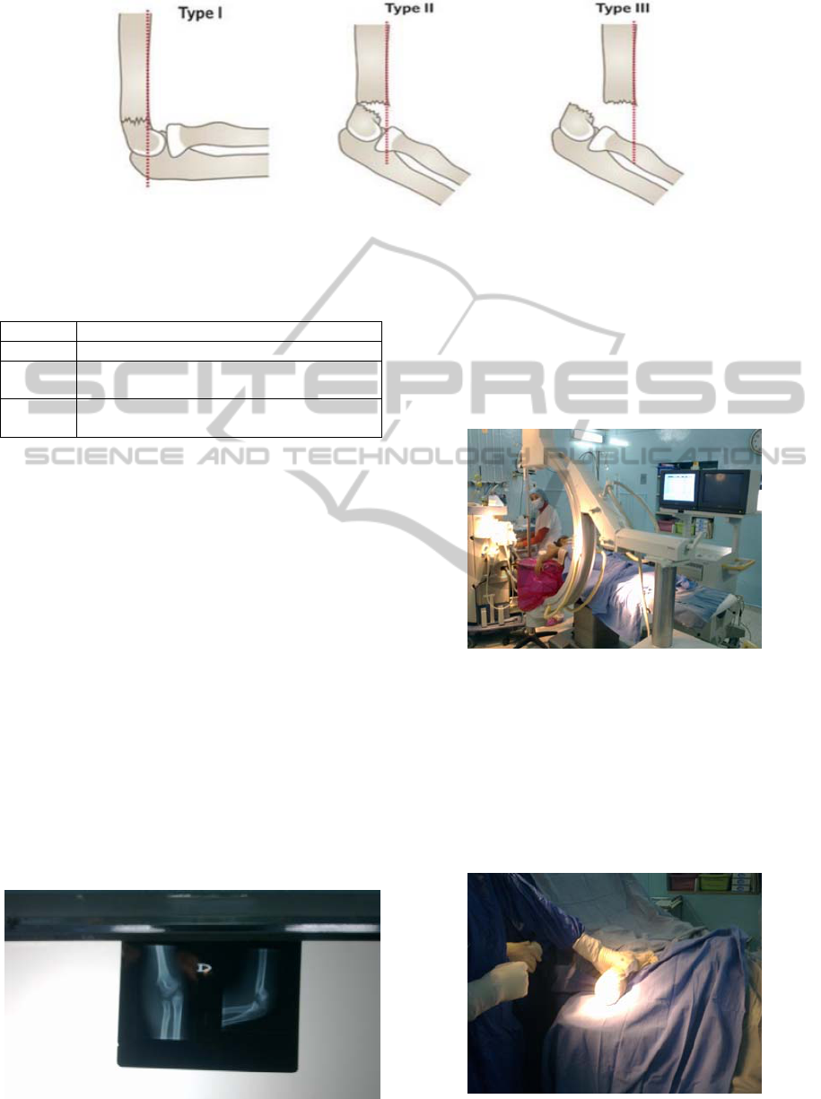
Figure 1: Gartland’s classification of supracondylar fractures of the humerus.
Table 1: Gartland’s classification of supracondylar
fractures of the humerus.
Type Radiologic characteristics
I Undisplaced fractures
II Displaced fracture with intact posterior
hinge
III Completely displaced fractures with no
contact between the fragments
3 CASE STUDY
We expose, in this section, a true case of a patient
suffering from a supracondylar humeral fracture
who came to the Children Hospital of Béchir Hamza
(Tunis). The patient who is a ten-year-old girl fell on
her outstretched right hand on November 12
th
2013.
Once supported, the patient's elbow was placed in a
brace in a 20-to-40° flexion to promote
vascularization of the organ. She underwent a
surgery on the same day. We were invited by
Prof.Dr.med. Mahmoud Smida, the head of Child
and Adolescent Orthopedics Service and our
medical collaborator, to attend the intervention.
Treatment with single traction is not considered
any more in modern centers due to a long required
hospitalization and excellent current surgical results.
The closed reduction with pinning is now the most
used technique. It is performed under general
Figure 2: The fracture's radiography.
anesthesia and fluoroscopic control. First, a
radiography of the injured elbow is taken to
determine the type of fracture. The latter was found
a type III fracture according to Gartland's
classification as show in Figure 2.
The patient, anesthetized, is then placed under
the fluoroscopic image intensifier (Figure 3).
Figure 3: The patient installed under the fluoroscopic
image intensifier.
The fracture is reduced in the frontal plane in
extension and the elbow is bent while pushing
forward the olecranon. The surgeon repeatedly
rotated the image intensifier rather than the limb and
took a total of 9 images to verify the reduction
profile. The limb is immobilized once a satisfying
reduction is obtained (Figure 4).
Figure 4: Limb immobilization.
BROS-ANewRoboticPlatformfortheTreatmentofSupracondylarHumerusFracture
153
Two percutaneous pinning are finally performed
in the distal fragment as illustrated in Figure 5 to fix
the bone and avoid any risk of cubitus varus (a
common deformity in which the extended forearm is
deviated towards midline of the body). To avoid any
vascular or nerve injury during the insertion of the
two pins, 15 fluoroscopic images were taken.
Figure 5: Percutaneous pinning.
During this surgery, a total of 24 fluoroscopic
images was taken, which involves high doses of
radiation to the medical staff, especially since such
interventions are performed 5 times per day on
average. The second pin had to be removed and
reinserted since it didn't straightaway follow the
right trajectory, which can lead to some
complications. To remedy these problems, we
launch a new project, baptized BROS, which
consists in a robotized platform to automatically
perform such surgeries or assist the surgeon by
limiting his exposition to radiations and bypassing
the blind pinning issue.
4 BROS
BROS is a new and original robotic platform. This
project was launched to remedy the two most
important difficulties the medical staff is facing: the
blind pining and the recurrent exposure to radiations.
We present in this section the BROS's
architecture and its operating modes.
4.1 Architecture
BROS is a robotic platform dedicated to humeral
supracondylar fracture treatment. It is able to reduce
fractures, block the arm and fix the elbow bone's
fragments by pinning. It also offers a navigation
function to follow the pins' progression into the
fractured elbow.
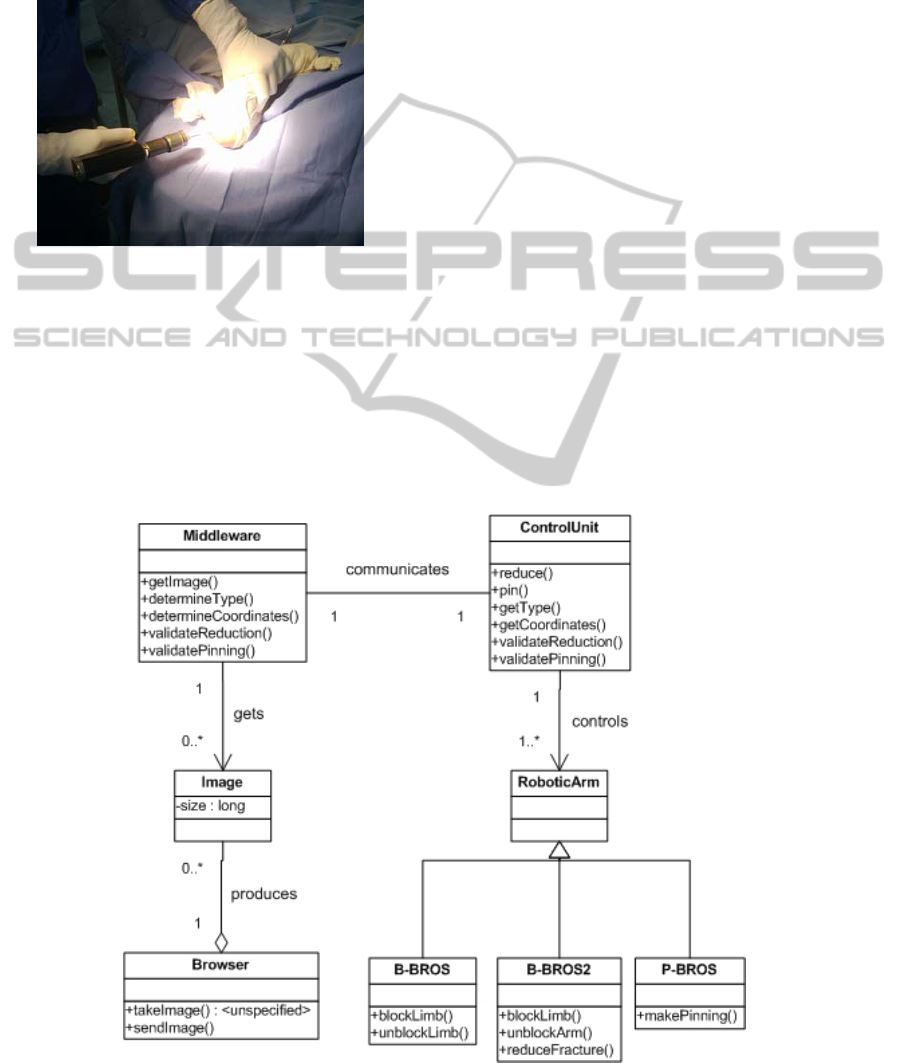
BROS is, as shown in the class diagram
hereafter, composed of a browser (BW), a control
unit (UC), a middleware (MW), a pining robotic arm
(P-BROS) and 2 blocking and reducing arms (B-
BROS1 and B-BROS2). The said components are
detailed hereafter.
Figure 6: BROS's class diagram.
HEALTHINF2015-InternationalConferenceonHealthInformatics
154

Browser
The browser, which is a Medtronics's product and
called FluoroNav, is a combination of specialized
surgical hardware and image guidance software
designed for use with a StealthStation Treatment
Guidance System. Together, these products enable a
surgeon to track the position of a surgical instrument
in the operating room and continuously update this
position within one or more still-frame fluoroscopic
images acquired from a C-Arm. The advantages of
this “virtual” navigation over conventional
fluoroscopic navigation include: (i) the ability to
navigate using multiple fluoroscopic views
simultaneously, (ii) the ability to remove the C-Arm
from the operative field during navigation, (iii)
significant reduction in radiation exposure to the
patient and staff.
In addition, the FluoroNav System allows the
surgeon to: (i) simulate and measure instrument
progression or regression along a surgical trajectory,
(ii) save instrument trajectories, and display the
angle between two saved trajectories or between a
saved trajectory and the current instrument
trajectory, (iii) measure the distance between any
two points in the camera’s field of view, (iv)
measure the angle and distance between a surgical
instrument and a plane passing through the surgical
field (such as the patient midplane).
Primary hardware components in the FluoroNav
System include the FluoroNav Software, a C-Arm
Calibration Target, a reference frame, connection
cables, and specialized surgical instruments.
Control Unit
The CU ensures the smooth running of the surgery
and its functional safety. It asks the supracondylar
fracture's type to the middleware, and then
computes, according to it, the different coordinates
necessary to specify the robotic arms' behaviors
concerning the fracture's reduction, blocking the arm
and performing pinning. The surgeon monitors the
intervention progress thanks to a dashboard installed
on the CU.
Middleware
The middleware is a software installed on the
browser and which acts as a mediator between the
CU and the BW. It is an intelligent component that
provides several features of real-time monitoring
and decision making. The middleware contains
several modules which are fully explained in Section
5: (i) an image processing module, (ii) a controller,
(iii) a communication module with the CU.
Pining Robotic Arm
The pining robotic arm, P-BROS, inserts two
parallel Kirschner wires according to Judet
technique (Judet, 1953) to fix the fractured elbow's
fragments. To insure an optimal postoperative
stability, BROS respects the formula:
0.22
(1)
where S is the stability threshold, B the distance
separating the two wires and D the humeral palette's
width (Smida et al., 2007).
Blocking and Reducing Robotic Arms
B-BROS1 blocks the arm at the humerus to prepare
it to the fracture reduction. B-BROS2 performs then
a closed reduction to the fractured elbow before
blocking it once the reduction is properly completed.
4.2 Reconfiguration and Operating
Modes
Reconfiguration is an important feature of BROS. It
is designed to be able to operate in different modes.
The surgeon can actually decide to manually do a
task if BROS does not succeed to automatically
perform it, whether it is facture reduction, blocking
the arm or pinning the elbow. Thus, five different
operating modes are designed and detailed hereafter:
(i) Automatic Mode (AM): The whole surgery is
performed by BROS. The surgeon oversees the
operation running, (ii) Semi-Automatic Mode
(SAM): The surgeon reduces the fracture. BROS
performs the remaining tasks, (iii) Degraded Mode
for Pining (DMP): BROS only realizes the pinning.
It's to the surgeon to insure the rest of the
intervention, (iv) Degraded Mode for Blocking
(DMB): BROS only blocks the fractured limb. The
remaining tasks are manually done by the surgeon,
(v) Basic Mode (BM): The whole intervention is
manually performed. BROS provides navigation
function using the middleware that checks in real
time the smooth running of the operation.
4.3 Humeral Supracondylar Fracture
Treatment
To treat a humeral supracondylar fracture using
BROS, the following steps are performed in the
automatic mode:
i. the surgeon launches the system and chooses
one of the five operating modes;
ii. CU asks MW about the fracture coordinates;
iii. MW requests an image from BW and the
latter sends it;
BROS-ANewRoboticPlatformfortheTreatmentofSupracondylarHumerusFracture
155
iv. MW determines the different coordinates by
image processing and sends them to CU;
v. based on the received coordinates, CU orders
B-BROS1 to block the arm at the humerus;
vi. B-BROS1 blocks the limb;
vii. CU asks B-BROS2 to reduce the fracture
based on the latter's line;
viii. B-BROS2 reduces the fracture;
ix. CU asks MW to ensure that the reduction
was successful;
x. MW requests a new image from BW and
checks the fracture reduction result. If it is
satisfactory, BROS moves to step xi. Steps
from vii. to ix. are repeated otherwise;
xi. CU orders B-BROS2 to block the arm;
xii. under the request of UC, P-BROS performs
the first and the second pinning;
xiii. once the pinning is successful, CU asks B-
BROS1 and B-BROS2 to unblock the limb.
Running example 1
To test our new robotized platform, we decided to
simulate the surgery that would be performed on a
real case. Thus, we chose a new patient, a nine-
year-old girl, suffering from a fracture similar to the
one presented in the case study of Section 3 (a a
type III fracture). We simulated the whole surgery
on June 9
th
2014 using the software RobotStudio
and the developed middleware and control unit. We
will present the obtained results as we introduce
these two components in the next sections.
5 MIDDLEWARE
We introduce in this section the architecture of the
middleware and its image processing module.
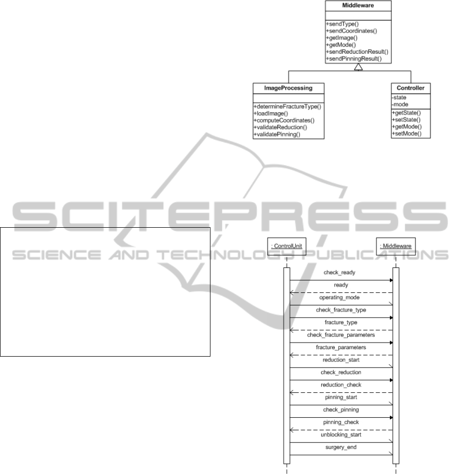
5.1 Architecture
The Middleware features two important modules:
the first performs operations relating to image
processing and the second insures the
synchronization and communication with the whole
robotized platform. Middleware's class diagram is
illustrated in Figure 7.
Since the middleware acts as a mediator between
the browser and the control unit, several data are
exchanged between MW and CU during the surgery.
First, the control unit notifies the start of the
intervention and the activated operating mode to the
middleware. Then, it asks it to compute necessary
parameters like fracture's type and spatial
coordinates. It also informs MW about the end of
Figure 7: Middleware's class diagram.
reduction and pinning. The middleware and the
control unit are connected through an ad hoc
network. We illustrate the different exchanges
between MW and CU by a sequence diagram as
shown in Figure 8.
Figure 8: Sequence diagram of communication with CU.
The controller is a module that saves the current
status reached by the intervention. Indeed, the
control unit informs the middleware of each fired
transition and the current triggered operating mode.
The control unit updates these information as the
intervention advances in time. Thus, the middleware
is kept aware of the progress of the surgery. This
module synchronizes, then, the middleware with the
whole operation.
The image processing module is deeply detailed
in the next section.
HEALTHINF2015-InternationalConferenceonHealthInformatics
156
5.2 Image Processing
Image processing is the most important module of
the middleware and provides a number features that
we detail below.
Locating
Locating is an important feature that involves setting
a spatial reference which is considered during the
whole intervention. The middleware and the control
unit must use the same coordinate system since
several points coordinates computed by MW are,
firstly, sent to CU so the latter performs a
preoperative simulation and, secondly, to B-BROS
and P-BROS to realize the fracture reduction and
pinning. We choose to fix the coordinate system
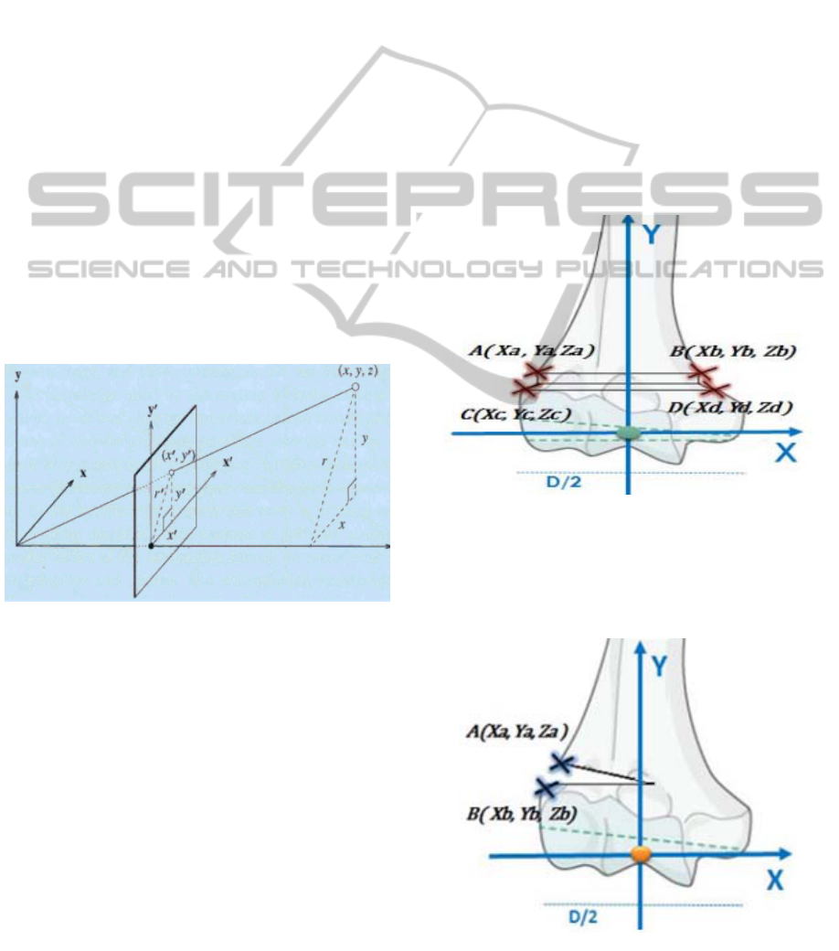
origin at the patient's elbow as illustrated in Figure
9. The X, Y and Z axes respectively represent the
elbow's rotation axis, the humeral palette length's
median and the normal to (XY) plan.
Figure 9: The coordinate system axes.
Determination of the Fracture Type
MW starts by receiving from BW a first image of
the fracture to determine its type. It compares the
acquired image with the ones stored in its database.
To do this, the middleware uses two image
processing techniques, ensuring, thus, proper
detection of the fracture type. The first one is image
matching and consists in comparing images in order
to obtain a measure of their similarity. It extracts
invariant local features for all images, and then uses
voting to rank the database images in similarity with
the query image (Grauman and Darrell, 2005). The
second used image processing technique is contour
comparison. It consists in detecting an image
contour by quantifying the presence of a boundary at
a given image location through local measurements
(Arbelaez et al., 2011). The contour comparison is
applied on the patient's elbow image acquired from
BW and images stored at the database, one at a time.
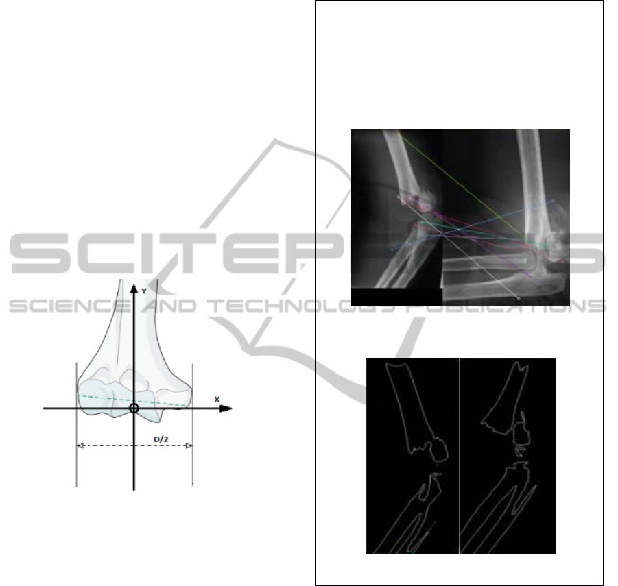
Running example 2
Figure 10 shows the result of image matching
applied on the running example's fractured elbow
(on the left) and an image from the MW database
(on the right). Figure 11, for its part, shows a
contour comparison with another image from the
database. The type III is confirmed.
Figure 10: Image matching applied on two fractured
elbow images.
Figure 11: Contour comparison performed by MW.
Coordinates Transformation
The middleware acquires images from the browser.
The latter uses a system camera composed of two
lenses to geometrically triangulate the spatial
coordinates of each light source on the instrument,
reference frame, and C-Arm Target. However, the
images it sends to MW are two-dimensional, and
MW needs to operate in a three-dimensional
environment to properly ensure the different steps of
the surgery, such as the fracture reduction and
pinning. Thus, we must, first, realize a camera
calibration which consists in finding the relationship
between the spatial coordinates of a point in space
BROS-ANewRoboticPlatformfortheTreatmentofSupracondylarHumerusFracture
157
(i.e. the operating theatre) and the associated point in
the image taken by the camera (Tsai, 1987). To
achieve the desired transformation, two type of
parameters must be determined:
the camera extrinsic parameters which define
the position and orientation of camera relative
to the space in which we work. Technically,
determining these parameters consists in
finding the translation vector between the
relative positions of the origins of two
references: the camera reference and the
operating theatre's. A rotation vector aligning
the axes of the two references must also be
computed.
the camera intrinsic parameters which are
required to bind the image pixels coordinates
with the corresponding ones in the camera
coordinate system. These parameters present
the camera optical, digital and geometric
features like the focal length, the geometric
distortion and image magnification factors.
Figure 12 illustrates the different used coordinate
systems where: (i) (x, y) plan is the image pixels
reference, (ii) (x', y', z') is the camera coordinate
system, (iii) (x, y, z) is the operating theatre
reference.
Figure 12: The different coordinate systems.
To translate the coordinates of a point in the image
from the latter's reference to the operating theatre's
and vice versa, we use the following formula:
1
Zconst
(2)
where : (i)
1
are the coordinates of a point in
the image, (ii)
M
is the camera matrix, (iii)
R
represents the rotation vector, (iv)
T
is the
translation vector, (v)
X, Y, Z
const
are the
coordinates corresponding to the point
S
in the
operating theatre reference.
Fracture Reduction Validation
The validation of fracture reduction consists in
checking whether the bone fragments regained their
original places or not. Thus, this module detects,
based on the acquired image, the bone discontinuity
and, then, computes the distance between the
displaced bone fragments. We hereafter explain this
technique with the most common fracture types of
Lagrange classification: II and III.
Validating the reduction of a type II fracture
involves calculating the distances AC and BD as
illustrated in Figure 13. A reduction is considered
successful when:
│
│││0
(3)
BROS has only three attempts to achieve a
successful reduction before switching to the semi-
automatic mode (SAM) to let the surgeon manually
perform it.
Figure 13: The reduction of a type II fracture.
The type III fractures usually present a rotary
disorder. Their reduction consists, therefore, in the
rotation of the forearm with an angle which is
arcsin (Z
b
- Za) as illustrated in Figure 14.
Figure 14: The reduction of a type III fracture.
HEALTHINF2015-InternationalConferenceonHealthInformatics
158
Pinning Validation
Pinning validation amounts to checking the respect
of the formula 1 introduced in section 4.1 by
computing the humeral palette's width and the
distance separating the two pins.
6 CONTROL UNIT
The control unit, the entity responsible of the smooth
running and the safety of surgery, is composed of
several modules which we detail hereafter. We use
RobotStudio to implement it and RobotWare
(Robotics, 2007) as the robot controller. Both are
ABB's products.
6.1 Station Definition
This module implements the station which is, in our
case, the operating room with all its components.
The latter can be grouped into two categories: the
mechanisms and the static components. The
mechanisms are objects that perform 3D motion
during simulations, whereas static components, as
their name suggests, remain fixed during all surgery.
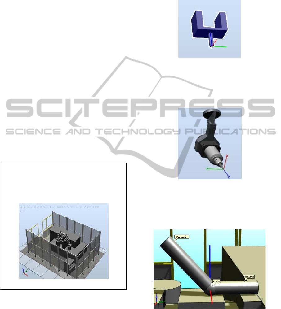
Running example 3
Figure 15 shows the implementation of our
operating theater with its different robotic arms,
the patient's limb modeling and the surgical bed.
Figure 15: The operating room definition.
Mechanisms
Our operating theatre's mechanisms are B-BROS1,
B-BROS2 and PBROS. They are all ABB's IRB 120
which we earlier presented in section 2.1. "Blocker
1" is the used tool to block the patient's limb at
humerus and lately unblock it according to
coordinates computed by the blocking module. To
reduce the fracture and block the limb at forearm,
"Blocker 2" is used according to coordinates
received from the reduction module. Blocker 1 and
Blocker 2 have the same 3D modeling illustrated in
Figure 16.
Figure 16: Blocker 1 and Blocker 2's 3D modeling.
"Pinning", as its name suggests, is the used tool to
perform pinning at the patient's elbow according
coordinates computed by the pinning module. Its 3D
modeling is showed in Figure 17.
Figure 17: Pinning's 3D modeling.
To simulate the progress of the surgery on the
patient's limb, we model the latter as illustrated in
Figure 18. It is modeled by a mechanism that rotates
about the X axis (in red).
Figure 18: Limb's 3D modeling.
Static Components
Static components are the different 3D objects which
are useful to the simulation like the robotic arms'
racks and the surgical bed.
BROS-ANewRoboticPlatformfortheTreatmentofSupracondylarHumerusFracture
159
6.2 B-BROS1 Module
B-BROS1 module describes the behavior of the
robotic arm B-BROS1 and how it blocks the
patient's limb at the humerus and unblocks it once
the surgery is completed. Thus, this module features
two procedures: (i) B_BROS1_humerusBlock () : it
blocks the arm at a distance of y+100 mm where y is
the coordinate on Y axis of the intersection point of
the humeral palette and its median. Figure 19
illustrates how the blocking is performed, (ii)
B_BROS1_humerusUnblock (): it releases the
patient's limb once the fracture treatment is
completed.
Figure 19: Blocking the patient's limb.
6.3 B-BROS2 Module
This module features several procedures which
allow robotized fracture reduction when the
automatic mode is triggered and direct robotized arm
blocking when AM, SAM or DMB is triggered. B-
BROS2 module releases the patient's limb once the
surgery is completed. We, hereafter, detail the
procedures: (i) B_BROS2_reduce_II (A, B, C, D) : it
performs the reduction of a type II fracture and takes
into account the parameters that we defined in
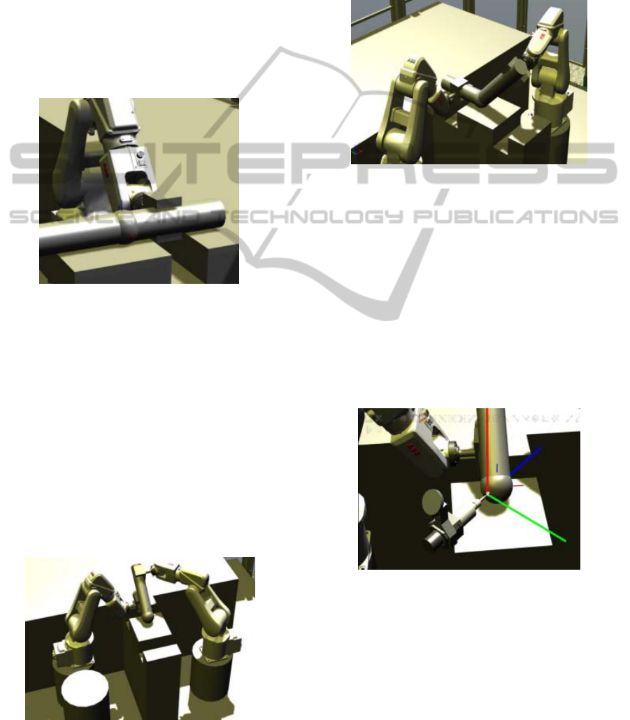
Section 5.2. Figure 20 illustrates a robotized
fracture reduction, (ii) B_BROS2_unblock_II (): this
procedure unblock the patient's limb suffering from
Figure 20: Robotized fracture reduction.
a type II fracture once the surgery is completed, (iii)
B_BROS2_reduce_III (A, B): it computes the
rotation angle of the rotary disorder in the case of a
type III fracture and, then, reduces the latter, (iv)
B_BROS2_block () : the procedure blocks the limb
at the forearm once a manual reduction is performed
during SAM or DMB. Figure 21 shows how this is
performed.
Figure 21: Blocking the fractured limb at the forearm.
6.4 P-BROS Module
This section describes the behavior of P-BROS, the
robotic arm performing fracture reduction according
to its type and the triggered operating mode. We
point out that the used pinning technique is Judet's
which we mentioned in Section 4.1. The orientation
of the tool "Pinning" (Section 6.1), relatively to the
coordinate system defined in Section 5.2, depends
on the type of the fracture. Thus, the figures 22 and
23 respectively shows the orientation of "Pinning" in
the case of a type II and a type III fractures.
Figure 22: Orientation of "Pinning" in the case of a
type II fracture.
The P-BROS module features several procedures
that we hereafter detail:(i) P_BROS_DoublePin (A,
B, C, D, HP) : it performs a parallel pinning using
two pins inserted from the external condyle to the
lateral humeral column in the case of a type II
fracture which requires a double pinning. The
procedure uses as parameters the four points of the
HEALTHINF2015-InternationalConferenceonHealthInformatics
160

Figure 23: Orientation of "Pinning" in the case of a type
III fracture.
distal dissolution and the width of the humeral
palette (HP), (ii) P_BROS_SinglePin_III (A, B, HP)
: this procedure performs a percutaneous pinning for
a type III fracture. The pin is actually inserted from
the external condyle throughout the medial column
in a rectilinear direction by keeping a fixed (XY)
plane, (iii) P_BROS_SinglePin_IV (A, B, HP) : it
realizes a percutaneous pinning for a type IV
fracture. Indeed, for this type of fracture, the pin is
inserted in the lateral condyle and makes an angle of
45° relative to the orientation of the pin in the case
of a type III fracture. The pin is inserted until
reaching the lateral column.
6.5 Synchronization Module
We present, in this section, the synchronization
module of the control unit. It is the entity that
insures the coordination between the tasks of B-
BROS1, B-BROS2 and P-BROS modules. To insure
this function, we use interruptions through binary
logic signals. Indeed, each signal corresponds to a
very specific task. The signal is high when the task
is running and low when it is idle or finished
executing. We note that the used signals represent
the steps of a fracture treatment based on the
operating mode and regardless to the nature of a
given action (robotized or manual).
We define for the control unit the following logic
signals which we detail in Table 2:
Table 2: Synchronization logic signals.
Logic Signal Description
HandBlocking
This signal controls the first step of a
fracture treatment which is blocking
the patient's limb at the humerus. It is
the highest priority task. The signal is
high when B-BROS1 starts blocking
the humerus and it switches to low
once blocking is finished.
Table 2: Synchronization logic signals (cont.).
HandReduction The signal controls the fracture
reduction and the forearm blocking. It
switches to high when HandBlocking
is low and either B-BROS2 starts the
robotized reduction and/or blocking or
the surgeon starts the manual reduction
and/or blocking. It is the second
priority task.
HandPinning HandPinning controls pinning, whether
it is manual or robotized. It changes to
high when the signal HandReduction
changes to low informing, thus, that
reduction and blocking are finished.
When it switches to high, HandPinning
starts pinning and switches to low once
it is finished.
HandUnblocking It controls the limb unblocking, which
is the lowest priority task.
6.6 CU-MW Communication Module
A good communication between the control unit and
the middleware is critical to the smooth functioning
of BROS. For example, the control unit cannot start
the different processing until it receives key
parameters like the fracture type and the coordinates
of the points of the distal fragment discontinuity.
The module respects the diagram presented in
Section 5.1.
6.7 Surgeon-Robot Interface
It is the graphical interface through which the
surgeon communicates with the platform and
oversees the progress of the operation. The surgeon
can, using this interface, choose the operating mode
to start with. Through this GUI, the surgeon consults
any medical parameter like the fracture type, the
displacement nature or the angle of the rotational
trouble in the case of type III fractures. This
interface meets the man-machine requirements like:
(i) Guidance: All resources used to guide the
surgeon during the use of the interface like
grouping/distinction, immediate feedback and
legibility, (ii) Workload: Minimum and explicit
actions ("start reduction", "start pinning"),
informational density more or less acceptable for a
surgeon, (iii) Error management: This is to protect
sensitive actions against errors with error messages,
(iv) Ergonomics: The interface must be flexible and
adaptable to a surgeon and especially in an operating
room.
BROS-ANewRoboticPlatformfortheTreatmentofSupracondylarHumerusFracture
161

Running example 4
The whole surgery was successfully performed
by BROS under the automatic operating mode
and simulated using RobotStudio and
RobotWare. Only 4 fluoroscopic images were
needed, what makes 21 images less than in the
study case introduced in Section 3. BROS
insured all the intervention steps and the surgeon
had only to remotely check the smooth running
of the surgery and be ready to intervene in the
case where the robotized platform would not be
able to perform one of the surgery's steps or he
would judge that a human intervention is
necessary.
7 CONCLUSION AND
PERSPECTIVES
Our work consisted, through this paper, in
introducing BROS, this new robotic platform
dedicated to the treatment of supracondylar humerus
fracture, and its contributions. BROS is a flexible
system since it may run under different operating
modes to meet the surgeon requirements and the
environment constraints: it is reconfigurable.
Through the simulation of a real case of BROS-
assisted surgery, we proved the usefulness of this
robotic platform to avoid the complications that may
be generated because of the blind pinning and
prevent the danger posed by the recurrent exposition
to radiations. We can, now, certify that BROS is an
innovating project which will be of a great help to
pediatric orthopedic surgeons. The next step is to
proceed to the real implementation of BROS using
the ABB robotic arms.
ACKNOWLEDGEMENTS
This research work is carried out within a
MOBIDOC PhD thesis of the PASRI program, EU-
funded and administered by ANPR (Tunisia). The
BROS national project is a collaboration between
the Children Hospital of Béchir Hamza (Tunis),
eHTC and INSAT (LISI Laboratory) in Tunisia. We
thank the medical staff, Prof.Dr.med. Mahmoud
Smida (Head of Child and Adolescent Orthopedics
Service) and Dr.med. Zied Jlalia, for their fruitful
collaboration and continuous medical support. A
second paper is submitted in the conference for the
modeling and verification of BROS.
REFERENCES
Arbelaez, P., Maire, M., Fowlkes, C., and Malik, J.
(2011).Contour detection and hierarchical image
segmentation. Pattern Analysis and Machine
Intelligence, IEEE Transactions on, 33(5):898–916.
Barton, K. L., Kaminsky, C. K., Green, D. W., Shean, C.
J., Kautz, S. M., and Skaggs, D. L. (2001). Reliability
of a modified gartland classification of supracondylar
humerus fractures. Journal of Pediatric Orthopaedics,
21(1):27–30.
Cardwell, M. An irb 120 robots picks and packs tubes of
hair color into boxes for l’oreal canada.
www.abb.com.
Cleary, K. and Nguyen, C. (2001). State of the art in
surgical robotics: clinical applications and technology
challenges. Computer Aided Surgery, 6(6):312–328.
Clein, N. W. (1954). How safe is x-ray and fluoroscopy
for the patient andthe doctor? The Journal of
pediatrics, 45(3):310–315.
Mikaelsson, P. and Curtis, M. (2009). Portrait-robot d'un
petit prodige: ABB présente son nouveau robot IRB
120 et son armoire de commande IRC5 Compact.
Revue ABB, (4), 39-41.
Connolly, C. (2009). Technology and applications of abb
robotstudio. Industrial Robot: An International
Journal, 36(6):540–545.
Emmerson, B. Irb 120 inserting thermoplastic trays in to
boxes for bdmo. www.abb.com.
Flynn, J. C., Matthews, J. G., Benoit, R. L., et al. (1974).
Blind pinning of displaced supracondylar fractures of
the humerus in children. J Bone Joint Surg Am,
56(2):263–72.
Gosens, T. and Bongers, K. J. (2003). Neurovascular
complications and functional outcome in displaced
supracondylar fractures of the humerus in children.
Injury, 34(4):267–273.
Grauman, K. and Darrell, T. (2005). Efficient image
matching with distributions of local invariant features.
In Computer Vision and Pattern Recognition, 2005.
CVPR 2005. IEEE Computer Society Conference on,
volume 2, pages 627–634 vol. 2.
Haque, M. U., Shufflebarger, H. L., OBrien, M., and
Macagno, A. (2006). Radiation exposure during
pedicle screw placement in adolescent idiopathic
scoliosis: is fluoroscopy safe? Spine, 31(21):2516–
2520.
Judet, J. (1953). Traitement des fractures sus-condyliennes
transversales de l'humérus chez l'enfant. Rev Chir
Orthop, 39:199–212.
Kwoh, Y. S., Hou, J., Jonckheere, E. A., and Hayati, S.
(1988). A robot with improved absolute positioning
accuracy for ct guided stereotactic brain surgery.
Biomedical Engineering, IEEE Transactions on,
35(2):153–160.
Lagrange, J. and Rigault, P. (1962). Fractures
supracondyliennes. Rev Chir Orthop, 48:337–414.
Landin, L. A. (1983). Fracture patterns in children:
Analysis of 8,682 fractures with special reference to
incidence, etiology and secular changes in a swedish
HEALTHINF2015-InternationalConferenceonHealthInformatics
162

urban population 1950-1979. Acta Orthopaedica,
54(S202):3–109.
Landin, L. A. and Danielsson, L. G. (1986). Elbow
fractures in children: an epidemiological analysis of
589 cases. Acta Orthopaedica, 57(4):309–312.
Pirone, A., Graham, H., Krajbich, J., et al. (1988).
Management of displaced extension-type
supracondylar fractures of the humerus in children. J
Bone Joint Surg Am, 70(5):641–50.
Rampersaud, Y. R., Foley, K. T., Shen, A. C., Williams,
S., and Solomito, M. (2000). Radiation exposure to the
spine surgeon during fluoroscopically assisted pedicle
screw insertion. Spine, 25(20):2637–2645.
Robotics, A. (2007). Application manual: Motion
coordination and supervision, robot controller,
robotware 5.0. Västeras, Sweden.
Smida, M., Smaoui, H., Ben Jlila, T., Saeid, W., Safi, H.,
Ammar, C., Jalel, C., and Ben Ghachem, M. (2007).
Un index de stabilité pour l'embrochage percutané
latéral parallèle des fractures supracondyliennes du
coude chez l'enfant. Revue de Chirurgie Orthopédique
et Réparatrice de l’Appareil Moteur, 93(4):404.
Tsai, R. Y. (1987). A versatile camera calibration
technique for high-accuracy 3d machine vision
metrology using off-the-shelf tv cameras and lenses.
Robotics and Automation, IEEE Journal of, 3(4):323–
344.
BROS-ANewRoboticPlatformfortheTreatmentofSupracondylarHumerusFracture
163
