
A Test Generator for Model-Based Testing
Ella Roubtsova
1
and Serguei Roubtsov
2
1
Open University of the Netherlands
2
Technical University Eindhoven, The Netherlands
1
Ella.Roubtsova@ou.nl,
2
s.roubtsov@tue.nl
Keywords:
Model Based Testing, Test Generator, Case Management Solutions.
Abstract:
The idea of software testing by software itself drives the attempts of creation of model based testing ap-
proaches. Model based testing relies on models, that encode the desired behaviour of a system, the relevant
behaviour of its environment; however, both the static and the behaviour models are not directly applicable
for model based testing. The models should be different from implementation and possess the observational
consistency allowing preservation behaviour of parts in the behaviour of the whole. The models need to be
built into a tool for preparation of the model and data for test generation. This paper proposes to use protocol
models for model based testing. A protocol model presents the external behaviour. Unlike other modelling
approaches, the Protocol Modelling semantics incorporates data into the model. This property gives us advan-
tages for the choice of the strategy of test generation. The main contribution of the paper is a combination of
algorithms for test generating from a protocol model. The preparation of a protocol model for test generation
and the results of test generation are illustrated with an example.
1 INTRODUCTION
What is a software test? It is a procedure or a se-
quence of actions that allows one to prove that the
software meets the requirements. A test may come
from requirements directly or may be generated (Fig-
ure 1) from a model different from the implementa-
tion model, as it is suggested in the UML test pro-
file (UML, 2005).
Requirements Model
System
Under Test
Test
Case
Test
Script
Test
Selection
Verdict
Feedback
Feedback
Feedback
Figure 1: Model-Based Testing.
Development of a dedicated test generation model
is often considered by system developers as unnec-
essary overhead, unless the model provides obvious
reduction of testing effort. The choice of a behaviour
modelling method with right properties facilitates re-
duction of testing effort and simplifies further system
maintenance.
The right properties of the modelling method de-
pend on the application domain. In this paper, we
focus on the domain of Case Management Solutions
(CMS), that covers the systems that “coordinate a ser-
vice request in finance, health, legal, citizen or human
resources-related matters, on behalf of a subject such
as a customer, a citizen, or an employee” (Davenport
and Nohria, 1994; Aalst van der and Weske, 2005).
The domain of Case Management Systems (CMSs)
has been defined in an OMG document. ”A Case is
a proceeding that involves actions taken regarding a
subject in a particular situation to achieve a desired
outcome... Case management planning is typically
concerned with determination of which Tasks are ap-
plicable, or which follow-up Tasks are required, given
the state of the Case. Decisions may be triggered by
events or new facts that continuously emerge during
the course of the Case, such as the receipt of new
documents, completion of certain Tasks, or achieving
certain Milestones. Individual Tasks that are planned
and executed in the context of the Case might be pre-
defined procedural Processes in themselves, but the
overall Case cannot be orchestrated by a predefined
sequence of Tasks. Representation of the circum-
stances and the decision factors in a Case model re-
quires references to data about the subject of the Case.
Modeling of constraints and guidance on the actions
to be taken in a Case requires the specification of rules
that reference the data in the CaseFile.... A new Case
model may be defined as entirely at the discretion of
103
Roubtsova E. and Roubtsov S.
A Test Generator for Model-Based Testing.
DOI: 10.5220/0005424801030112
In Proceedings of the Fourth International Symposium on Business Modeling and Software Design (BMSD 2014), pages 103-112
ISBN: 978-989-758-032-1
Copyright
c
2014 by SCITEPRESS – Science and Technology Publications, Lda. All rights reserved

human participants initially, but it should be expected
to evolve as repeatable patterns and best practices
emerge.” (OMG, 2013) A CMS supports communica-
tion of the system with different business actors. The
system reaction to the requests of actors is determinis-
tically defined by business rules. It should not contain
implementation details. Business rules are formulated
using visible states of the system expressed with data.
Therefore, the behaviour modelling method should
(1) result in a deterministic models,
(2) present only visible system states and
(3) enable expressions with relevant data and data
transformation.
The distinguished property of these systems is the fre-
quent need of change and subsequent testing due to
the changes of law regulations and business optimiza-
tion. Modelling approaches which facilitate indepen-
dent modelling of a change and its composition with
the old model can reduce modelling and testing effort.
In this paper, we address the problem of model-
based testing of CMSs. First, we analyse the mod-
elling techniques in order to select the one that is
the most suitable for CMSs. Second, we propose a
method of using the chosen modelling technique for
test generation and the corresponding algorithms.
2 MODELLING APPROACHES
TO MODEL-BASED TESTING
The first research question that we answer in the paper
is: Is there a modelling approach most suitable to the
domain of Case Management Systems?
We start our analysis with the approaches stan-
dardised in the UML (OMG, 2003).
2.1 Modelling Approaches in the UML
Use Cases are used to describe the scenarios of inter-
actions between the system and the environment. Use
Cases are presented in a combination of the natural
language and informal diagrams. The informal and
partial use case does not cover system requirements,
does not use data, does not support the composition
of models.
Interaction Diagrams (Sequence Diagrams and
Communication Diagrams) can be used to express in-
teraction of communicating objects during their life-
time. Normally, one such diagram presents one se-
quence of interaction. If decision points are used, an
interaction diagram can present a restricted number
of sequences. A set of interaction diagrams usually
presents only a subset of possible sequences. Com-
position of interaction diagrams is not defined in the
UML. The suggestions for ”mechanical” composi-
tion (Roubtsova and Kuiper, 2003; Greenyer et al.,
2008; Hanenberg et al., 2007) do not guarantee the
specification of complete behaviour.
Activity Diagrams provide a flow based model-
ing medium, similar to Petri Nets (Petri and Reisig,
2008). They are used to show “the sequence and
conditions for coordinating behaviors” rather than be-
haviours of objects. (OMG, 2003). This means that
Activity Diagrams are not suitable for representing
the behavior of an object model and, as a conse-
quence, the separate modelling of requirements is not
always possible.
State Machines exist in two variants: Behavioral
State Machines (BSM) and Protocol State Machines
(PSM) (OMG, 2003).
A Behavior State Machine usually presents behav-
ior of one class. “Behavior is modeled as a traversal
of a graph of state nodes interconnected by one or
more joined transition arcs that are triggered by the
dispatching of series of (event) occurrences. During
this traversal, the state machine executes a series of
activities associated with various elements of the state
machine.” (OMG, 2003) A transition label e[g]/a in-
cludes an event e that triggers the transition, a guard
g that restricts the condition of a transition firing and
the action a that happens if the transition takes place.
The composition semantics for BSMs defines an event
queue which holds the incoming event instances un-
til they are dispatched, an event dispatcher mecha-
nism that selects event instances from the queue, and
an event processor which processes dispatched event
instances according to the general semantics of the
UML state machines. Event instances being results of
some actions within the system or in the environment
are conveyed to one or more BMSs (OMG, 2003). An
event is received by a BMS if it is placed on the event
queue of the BMS. An event is dispatched when it is
removed from the queue and delivered to the state ma-
chine for processing. If an event is dispatched, it may
result in one or more transitions. If no transition is
enabled, then the event is discarded. Finally the event
is consumed and it is no longer available for process-
ing. The consumption of events depends on the active
state of a state machine. If an event triggers a tran-
sition in the current state, it is dispatched and con-
sumed. “A state may specify a set of event types that
may be deferred in the state. An event instance that
does not trigger any transition in the current state will
not be dispatched if its type matches with the type
of one of the deferred events. Instead it remains in
the event queue while another not deferred message
is dispatched instead” (OMG, 2003). In other words,
• if an event recognized by a machine that enables
Fourth International Symposium on Business Modeling and Software Design
104

a transition in its current state, then it can be con-
sumed;
• if an event recognized by a machine that does not
enable a transition in the current, an this event is
included in the list of deferred events for this state,
it is kept in a queue for later processing;
• otherwise the event is discarded (McNeile and
Roubtsova, 2009).
This means that processing of an event by different
machines is asynchronous and the result of processing
is non-deterministic. If an event can cause firing of
two transitions, which transition can happen first is
not defined.
Thus, BSMs do provide complete behavior de-
scriptions and can provide model based execution
needed for MBT. However, BSM do not result in de-
terministic models and do not meet our requirements
for the modelling method for MBT of CMS.
The UML Protocol State Machines (PSMs) are
used to express the transitions that a classifier can trig-
ger. A PSM is a way to define a life cycle of an ob-
ject, or an order of the invocation of its operations.
PSMs can express usage scenarios of object classes
and interfaces. The effect actions of transitions are
not specified in a PSM transition as the trigger itself
is the operation. However, pre- and post- conditions
are specified, so that the label of a transition is of
the form [precondition] event/ [postcondition]. The
occurrence of an event that a PSM cannot handle is
viewed as a precondition violation, but the consequent
behavior is left open. “The interpretation of the recep-
tion of an event in an unexpected situation (current
state, state invariant, and pre-condition) is a semantic
variation point: the event can be ignored, rejected, or
deferred; an exception can be raised; or the applica-
tion can stop on an error. It corresponds semantically
to a pre-condition violation, for which no predefined
behavior is defined in UML” (OMG, 2003). Unlike
BSMs, PSMs can (to a limited extent) be composed.
“A class may have several protocol state machines.
This happens frequently, for example, when a class
inherits several parent classes having protocol state
machine, when the protocols are orthogonal.” (OMG,
2003). However, the semantics of composition for
PSMs is undefined.
As a result of the above analysis we conclude that
none of the UML behaviour modelling approaches are
satisfying enough to meet the requirements to mod-
elling Case Management Systems.
2.2 Outside the UML
The MBT approaches often experiment with labeled
transition systems with different semantics. For ex-
ample, the Labelled Transition Systems (LTSs) used
by Kervinen at al. (Kervinen et al., 2006) (s
0
,S,E,T )
( s
0
is an initial state; S - a set of states; E is a set
of events; T ⊆ S × E × S) is a deterministic model.
There is no state in which any output transition share
the same action name. The LTSs can be composed us-
ing the CSP parallel composition (Hoare, 1985). Also
there are rules of matching events that are used for
synchronous composition.
LTSs used by Kervinen at al. (Kervinen et al.,
2006) meet most of our requirements to the modelling
method for CMS. Such LTSs are able to provide the
basis of MBT implementation. The shortcoming is
their abstraction from data.
The Protocol Modelling technique (McNeile and
Simons, 2006) overcomes the above mentioned short-
comings of LTSs. Protocol Modelling uses the CSP
parallel composition (Hoare, 1985) extended by A.
McNeile to enable the composition of models with
data (McNeile and Simons, 2006). It is proven
in (McNeile and Roubtsova, 2008) that protocol mod-
els possess the property called observational consis-
tency. This property means that a protocol machine
may be added to and deleted from the model or lo-
cally changed and the trace behaviour of other proto-
col machines is not affected by the behaviour of of the
added, deleted or modified protocol machines (Mc-
Neile and Roubtsova, 2008). We argue that, poten-
tially, observational consistency of protocol models
can reduce the modelling and testing effort when the
CMS is changed.
3 PROTOCOL MODELLING FOR
MBT
Our second research question is: How can a protocol
model be used for test generation?
3.1 What is a Protocol Model?
The building blocks of a Protocol Model are proto-
col machines and events. They are instances of corre-
spondingly protocol machine types and event types.
A protocol machine type is an LTS extended to
enable modelling with data:
PM
i
= (s
0
i
,S
i
,E
i
,A
i
,CB
i
,T
i
), where
• s
0
i
is the initial state;
• S
i
is a non-empty finite set of states.
• E
i
is a finite set of recognized event types e
i
, com-
ing from the environment.
A Test Generator for Model-Based Testing
105
• A
i
is a finite set of attributes of different types.
The set can be empty.
• CB
i
(PM
1
,..., PM
n
,E
1
,..., E
m
) =
(PM
1
,..., PM
n
,E
1
,..., E
m
)
is a callback function for updating the values of
the attributes, states and events of the protocol
machines of the protocol model. PM
1
,..., PM
n
are the protocol machines of the protocol model.
E
1
,..., E
m
are events of the protocol model. The
default callback function (the absence of the call-
back) does not change the model elements.
• T
i
⊆ S
i
× E
i
× S
i
a finite set of transitions:
t = (s
x
,e,s
y
), s
x
,s
y
∈ S
i
, e ∈ E
i
. The set of tran-
sitions can be empty. The states may be updated
without callback functions. The values of the at-
tributes, states and events may be updated using
the callback function only as a result of a transi-
tion, i.e. as a result of an event acceptance.
In order to facilitate reuse, protocol machines
come in two variants: Objects and Behaviours. Be-
haviours cannot be instantiated on their own but may
extend functionality of objects. In a sense, objects
with included behaviours are similar to mixins in
programming languages (Bracha and Cook, 1990).
An event type is a tuple
e = (EventName,A
e
,CB
e
)
• A
e
is a finite set of attributes of the event.
• CB
e
(PM
1
,..., PM
n
,E
1
,..., E
m
) =
(PM
1
,..., PM
n
,E
1
,..., E
m
)
is a callback function corresponding to this event.
A default callback function (the absence of it)
does not changes the model elements. The call-
back function for an event is used if the event cal-
culates attributes of generates other events from
the state of the model.
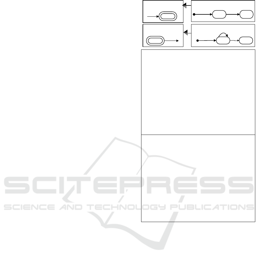
An example of a protocol model is shown in Fig-
ure 2. It is a model of a small case management
system for handling a document. Unique document
parts are submitted to a document. When all parts
have been submitted, the document can be submit-
ted. to a document by participants of a project. There
are four protocol machines in Figure 2: OBJECT
Part with included BEHAVIOUR Duplicate Check
and OBJECT Document with included BEHAVIOUR
Document Submittable. The protocol machines are
described textually as sets of their attributes, states
and transitions. A behaviour protocol machine is al-
ways included into at least one object protocol ma-
chine. The INCLUDES relation is shown on the top
of Figure 2 graphically as an arc with a half-dashed
submitted
Create Part Submit Part
Part
created
Create Doc
Document
Create Part,
Submit Part
creates
unique
Create Part
Duplicate Check
public class DuplicateCheck extends Behaviour {
public String getState() {
String myName=getString("Name");
Instance[] existingIns = this.selectInState(this.getObjectType(), "@any");
for (int i = 0; i < existingIns.length; i++)
if (existingIns[i].getString("Name").equals(myName) &&
!existingIns[i].equals(this))
return "duplicate";
return "unique";
}
}
public class DocumentSubmittable extends Behaviour {
public String getState() {
boolean allSubmitted =true;
Instance[] myParts = this.selectByRef("Part", "Document");
if (myParts.length==0)
{allSubmitted = false;}
for (int i = 0; i < myParts.length; i++) {
if ((myParts[i].getState("Part").equals("created")))
allSubmitted = false;
}
return allSubmitted ? "submittable" : "not submittable";
}
public String getDocumentStatus() {
return this.getState("DocumentSubmittable");
}
}
OBJECT Part
NAME Name
INCLUDES Duplicate Check
ATTRIBUTES Name: String,
STATES created ,submitted
TRANSITIONS @new* Create Part= created,
created*Submit Part=submitted
BEHAVIOUR !Duplicate Check
STATES unique, duplicate
TRANSITIONS @any*Create Part=unique
OBJECT Document
NAME Name
INCLUDES DocumentSubmittable
ATTRIBUTES Name:String,
STATES created, submitted, cancelled
TRANSITIONS @new*CreateDoc=created,
created*CreatePart=created,
created*SubmitDoc=submitted
BEHAVIOUR !DocumentSubmittable
# Ensures that a document cannot be
#submitted if it has unfinished Parts
ATTRIBUTES !Document Status: String
STATES submittable, not submittable
TRANSITIONS submittable*SubmitDoc=@any
EVENT Create Part
ATTRIBUTES
Part: Part,
Name: String,
Document: Document
EVENT Submit Part
ATTRIBUTES
Part :Part,
Document: Document
EVENT CreateDoc
ATTRIBUTES
Document:Document,
Name:String,
EVENT SubmitDoc
ATTRIBUTES
Document: Document,
submittable
Submit
Doc
Document
Submittable
submitted
Submit Doc
Figure 2: Protocol Model of a Document that consists of
Parts.
arrowhead. Each of behaviours has the corresponding
callback presented as a small Java function. The call-
back of the behaviour Duplicate check returns states
unique or duplicate. The callback of the behaviour
Document Submittable returns the state submittable,
not submittable. There are four event types in the
model presented with their attributes: Create Part,
Create Doc, Submit Part and Submit Doc.
3.2 Data Handling and Its Use for MBT
Within the Protocol Modelling, the callback functions
are the instruments for data handling. In the Mod-
elScope tool (McNeile and Simons, 2000) supporting
execution of protocol models, the callbacks are coded
as small Java classes with methods changing and/or
returning the values of attributes and states of in-
Fourth International Symposium on Business Modeling and Software Design
106

stances of protocol machines. They may also change
attributes of events and generate event instances.
Usually transitions t ∈ T
i
of a protocol machine
PM
i
enable updates of its own states of the state set
S
i
. On the other hand, protocol machines can read
the states of each other, although cannot change them.
This property creates dependencies of protocol ma-
chines. The dependency means that one protocol ma-
chine needs to read the state of another machine to
calculate its own state and/or the attributes. Such cal-
culated states are called derived states, which distin-
guishes them from the ”stored” states denoted in the
model (McNeile and Simons, 2006). Callback func-
tions CB
i
are used to update attributes and calculate
derived states.
There are two possibilities in dependent machines:
(1) The pre-state of a transition can be calculated. The
pre-state is similar to a guard calculated in the UML
state machines. BEHAVIOUR Document Submittable
is an example of a pre-state.
(2) The predicted after-state of a transition can be
calculated and used to allow or refuse the event.
This predicted after-state is a unique feature of Pro-
tocol modelling. Both behaviour protocol machines
in Figure 2 have the after-states. For example, BE-
HAVIOUR Duplicate Check derives state unique or
duplicate after event CreatePart and enables the event
only if the Part has a unique name. If an event is not
enabled, the protocol machine is rolled back to the
previous state of the model.
As the state of a dependent machine is changed
by the corresponding callback, not by a transition,
the dependency between protocol machines needs to
be taken into account for test generation. Using the
information in the callbacks, the derived states of a
protocol machine can be visualised in the model with
the corresponding stored states with the same names.
The state changes, coded in the callbacks, can be pre-
sented as transitions. The transformed in such a way
protocol machines with derived states, are called con-
nected forms (McNeile and Roubtsova, 2012). They
have been used for workflow analysis of protocol
models. We propose to use them for test generation.
Currently, we perform the model transformation as a
manual procedure.
For example, the callback Duplicate Check ex-
tends behaviour BEHAVIOUR Duplicate Check.
The state duplicate may appear during the pro-
ceeding of event CreatePart but it should be rolled
back. This means that there is no continuation of the
test possible with the duplicated Part. In such a situa-
tion, the ModelScope tool generates an error message.
The working protocol model of BEHAVIOUR Dupli-
cate Check contains only one transition (Figure 2).
BEHAVIOUR !DuplicateCheck
STATES unique, duplicate
TRANSITIONS @any*CreatePart=unique,
Using the information from the callback we create
the connected form being a non-deterministic proto-
col machine intended to be used for test generation. It
contains two transitions for event CreatePart and the
third transition for the event SubmitPart possible only
in state unique:
BEHAVIOUR !DuplicateCheck
STATES unique, duplicate
TRANSITIONS @any*CreatePart=unique,
@any*CreatePart=duplicate,
unique*SubmitPart=unique
3.3 Analysis of CSP Parallel
Composition and It Use for MBT
Another observation concerns the use of the CSP
composition.
A protocol model contains only the protocol ma-
chine types serving as patterns for creating instances
of protocol machines. In the initial state, a protocol
model PM is a CSP parallel composition of the pro-
tocol machines each of which corresponds to a pro-
tocol machine type in the initial state @new. The in-
stances of protocol machines of each type are created
as a result of an acceptance of an event that transits
the machine from the state @new to some state of the
machine life cycle.
In any state, a system model PM is a CSP paral-
lel composition of finite set of instances of protocol
machines.
n
PM = kPM
i
= (s
0
,S, E, A,CB, T ), n ∈ N.
i = 1
A Protocol Model PM is also a protocol machine,
the set of states of which is the Cartesian product of
states of all composed protocol machines (McNeile
and Simons, 2006):
n
s
0
=
S
s
0
i
is the initial state;
i = 1
n
S =
∏
S
i
is the set of states;
i = 1
n
E =
S
E
i
is the set of events;
i = 1
n
A =
S
A
i
is the set attributes of all machines;
i = 1
n
CB =
S
CB
i
is the set of callbacks of all machines.
i = 1
A Test Generator for Model-Based Testing
107

The set of transitions T of the protocol model is
defined by the rules of the CSP parallel composi-
tion (Hoare, 1985). The rules synchronise transitions
T
i
of protocol machines. Namely, a Protocol Model
handles only one event at a time. An event can be ac-
cepted only if all protocol machines having this event
in their alphabets are in the state where they can ac-
cept this event. Otherwise the event is refused.
As a protocol machine can contain several in-
stances of a certain type, tests should be able to dif-
ferentiate them. This is possible since each OBJECT
has a NAME attribute by which it can be identified. In
our example in Figure 2 all events have only one link
to object Part. This means that only one instance is
used.
Similarly, any BEHAVIOUR can be included in
several objects. In such cases the corresponding ob-
ject model contains INCLUDES statement (see Figure
2) with the name of included BEHAVIOUR type. Al-
though BEHAVIOUR does not have a NAME attribute,
it can be uniquely identified in tests by the NAME at-
tribute of the host OBJECT.
4 TEST GENERATION
Our proposed Protocol Model Based test generation
technique consists of the following steps:
- Creation of object models for all individual protocol ma-
chines;
- Iterative generation of the System Protocol Machine, us-
ing the CSP composition;
- Generation of test traces for the system protocol machine.
4.1 Creation of Object Models for
Individual Protocol Machines
Our test generation starts with building object models
containing all such ’first class’ model elements as pro-
tocol machines (objects and behaviours), events and
callbacks as well as their attributes, states, transitions.
These models are built by parsing the system protocol
model textual representations in Figure 2.
4.2 Iterative Generation of the System
Protocol Machine
The fact that the CSP parallel composition of protocol
machines is a protocol machine allows us to imple-
ment the iterative algorithm for generating the system
protocol machine from the models of objects and be-
haviours obtained at the first step (Algorithm 1).
Algorithm 1: Algorithm for CSP parallel composition k of
all protocol machines.
GIVEN:Set of Protocol machines from the protocol model
{PM
i
}, i = 0,...n
RESULT: CSP parallel composition of all protocol machines of
the protocol model SystemPM = kPM
i
i = 0,...n
Algorithm:
SystemPM = PM
0
i = 1
while (i <n) do
Algorithm 2 for CSP composition k of two Protocol Ma-
chines
SystemPM = SystemPMkPM
i
i++
end while
Algorithm 2: Algorithm for CSP composition k of two Pro-
tocol Machines.
GIVEN:
Object (behaviour) O
1
:
Transitions O
1
: x
i
∗ A = x
j
. Set of events E
1
. Set of states S
1
.
Object (behaviour) O
2
:
Transitions O
2
: y
k
∗ A = x
h
. Set of events E
2
. Set of states S
2
.
RESULT: CSP parallel composition O
1
kO
2
.
Algorithm:
Find E
1
∩ E
2
.
for Each e ∈ E
1
∩ E
2
do
Find transitions of O
1
: O
1
.x
i
∗ e = O
1
.x
j
, labeled by e.
Find transitions of O
2
: O
2
.y
k
∗ e = O
2
.y
h
, labeled by e.
Construct the transition of the composition of O
1
kO
2
:
O
1
.x
i
;O
2
.y
k
∗ e = O
1
.x
j
;O
2
.y
h
.
Add the initial and end states of the transition to the set of
states of O
1
kO
2
.
Add e to the set of events of O
1
kO
2
.
end for
for Each a /∈ E
1
∩ E
2
do
Find transitions of O
1
: O
1
.x
i
∗ a = O
1
.x
j
labeled by a;
for All states of O
2
: y do
Construct transition of O
1
kO
2
: O
1
.x
i
;O
2
.y ∗ a =
O
1
.x
j
;O
2
.y;
Add initial and end states of the transition to the set of
states of O
1
kO
2
Add a to the set of events of O
1
kO
2
end for
Find transitions of O
2
: O
2
.y
k
∗ a = O
2
.x
h
labeled by a;
for All states of O
1
: x do
Construct transitions of O
1
kO
2
: O
1
.x; O
2
.y
k
∗ a =
O
1
.x; O
2
.y
h
;
Add initial and end states of the transition to set of states
of O
1
kO
2
Add a to the set of events of O
1
kO
2
end for
end for
The Algorithm 2 for CSP composition k of two
Protocol Machines reflects the synchronization of
protocol machines. The rules of the CSP composition
say that an event is accepted by the Protocol Model if
it is accepted by both protocol machines if they both
contain this event in their event sets, otherwise it is
refused. This means that if the transitions of two pro-
tocol machines are labeled with the same event, then
their initial and final states are united to produce a
synchronised transition. If an event belongs to the set
of only one of protocol machines (in the set of two),
then the state of this machine is changed according to
Fourth International Symposium on Business Modeling and Software Design
108

Traces for OBJECT Part & BEHAVIOUR !DuplicateCheck
1)Part.@new&!DuplicateCheck.@new*CreatePart=Part.created&!DuplicateCheck.unique-->
Part.created&!DuplicateCheck.unique*SubmitPart=Part.submitted&!DuplicateCheck.unique-->
|
2)Part.@new&!DuplicateCheck.@new*CreatePart=Part.created&!DuplicateCheck.duplicate-->
Traces for OBJECT Document & BEHAVIOUR Document Submittable & OBJECT Part & BEHAVIOUR !DuplicateCheck
1)Document.@new&DocumentSubmittable.@new&Part.@new&DuplicateCheck.@new*CreateDoc=Document.created&DocumentSubmittable.notSubmittable&Part.@new&DuplicateCheck.@new-->
Document.created&DocumentSubmittable.notSubmittable&Part.@new&DuplicateCheck.@new*CreatePart=Document.created&DocumentSubmittable.notSubmittable&Part.created&DuplicateCheck.unique-->
Document.created&DocumentSubmittable.notSubmittable&Part.created&DuplicateCheck.unique*SubmitPart=Document.created&DocumentSubmittable.submittable&Part.submitted&DuplicateCheck.unique-->
Document.created&DocumentSubmittable.submittable&Part.submitted&DuplicateCheck.unique*SubmitDoc=Document.submitted&DocumentSubmittable.submittable&Part.submitted&DuplicateCheck.unique-->
|
2)Document.@new&DocumentSubmittable.@new&Part.@new&DuplicateCheck.@new*CreateDoc=Document.created&DocumentSubmittable.notSubmittable&Part.@new&DuplicateCheck.@new-->
Document.created&DocumentSubmittable.notSubmittable&Part.@new&DuplicateCheck.@new*CreatePart=Document.created&DocumentSubmittable.notSubmittable&Part.created&DuplicateCheck.duplicate-->
Figure 3: Traces of the Part with Duplicate check and the model of a Document with one Part.
its transition, and the state of the other machine re-
mains unchanged.
4.3 Generation of Test Traces for the
System Protocol Machine
To generate tests we use the set of transitions of
SystemPM obtained at the previous step. The precon-
ditions are the following:
- Each unique trace has to start from the transition in which
the initial state of each object is @new. This way a test case
can cover the whole life cycle of the objects involved in a
trace.
- Each possible transition in a particular trace has to be re-
peated only once. This way we decrease the number of test
steps while still providing complete transition coverage.
Algorithm 3 : Generation of test traces for the protocol
model.
GIVEN: Transitions T of SystemPM: (x,e,y),x,y ∈ S, e ∈ E
RESULT: test case traces for SystemPM
Algorithm:
Initial state of the system l =”all objects in state @new”.
for each t ∈ T do
if The input state of t x ⊆ l then
Add t to the set of transitions T
j
, j = 0,...,k possible in
the initial state ”all objects in state @new”
end if
end for
for Each T
j
, j= 0,...,k do
Apply the Algorithm for Transition Tree Generation for T
j
Make a trace by Traversing Transition Tree for T
j
end for
Algorithm 4: Transition Tree Generation recursively makes
a tree of traces starting with the initial transition T
j
.
GIVEN:
Transitions T of SystemPm
Transition T j for which precondition 1 holds
Result: test case traces for T
j
as an initial transition
Algorithm:
Add T
j
to a tree as a node
remove T
j
from T /* to enforce precondition 2*/
for each t ∈ T do
if initial state t = end state of T
j
then
Transition Tree Generation for t
end if
end for
Traversing Transition Tree from the initial transi-
tion T
j
is straight forward. Each trace starts from the
initial transition and stops in a leaf for which no tran-
sition exists with the initial state equal to the end state
in the current leaf. Termination is assured because at
each step in the trace the corresponding transition is
removed from the finite set T .
4.4 Results of Test Generation
We implemented the above algorithms as a Java ap-
plication. As we already mentioned, changeability is
an immanent feature of Case Management Systems.
In order to support testing of changeability, the traces
can be built evolutionary. The task of regression test-
ing (Myers, 2004) is selecting the minimal set of tests
required to cover a particular change. Reducing the
regression testing can contribute significantly in de-
creasing the overall testing effort.
Let us assume, that the model for OBJECT Part
with BEHAVIOUR Duplicate Check was created first.
After that it was extended to a composed model OB-
JECT Document, BEHAVIOUR Document Submit-
table, OBJECT Part, BEHAVIOUR !DuplicateCheck.
Traces for OBJECT Part with BEHAVIOUR Du-
plicate Check are shown on the top of Figure 3.
Traces for the composed model OBJECT Document,
BEHAVIOUR Document Submittable, OBJECT Part,
BEHAVIOUR !DuplicateCheck are show on the bot-
tom of Figure 3.
As we can see, lines 2 and 3 of the trace 1 of the
composed model include the trace 1 of the OBJECT
Part with BEHAVIOUR Duplicate check. The states
of OBJECT Document, BEHAVIOUR Document Sub-
mittable are not changed in this trace. Similarly, line
2 of trace 2 includes the trace 2 of OBJECT Part, BE-
HAVIOUR Document Submittable. This means that
there is no need to repeat the tests of OBJECT Part,
BEHAVIOUR Duplicate check for regression testing.
The property of observational consistency of Protocol
Models works for reduction of regression testing.
A Test Generator for Model-Based Testing
109

Traces for OBJECTPart&BEHAVIOUR!DuplicateCheck
1)Part.@new&!DuplicateCheck.@new*CreatePart=Part.created&!DuplicateCheck.unique-->
Part.created&!DuplicateCheck.unique*SubmitPart=Part.submitted&!DuplicateCheck.unique-->
|
2)Part.@new&!DuplicateCheck.@new*CreatePart=Part.created&!DuplicateCheck.duplicate-->
Traces for OBJECTDocument&OBJECTDocumentSubmittable&
OBJECTPart1&OBJECTDuplicateCheck1&OBJECTPart2&OBJECTDuplicateCheck2
1)Document.@new&DocumentSubmittable.@new&Part1.@new&DuplicateCheck1.@new&Part2.@new&DuplicateCheck2.@new*CreateDoc=Document.created&DocumentSubmittable.notSubmittable&Part1.@new&DuplicateCheck1.@new&Part2.@new&DuplicateCheck2.@new-->
Document.created&DocumentSubmittable.notSubmittable&Part1.@new&DuplicateCheck1.@new&Part2.@new&DuplicateCheck2.@new*CreatePart[Part2]=Document.created&DocumentSubmittable.notSubmittable&Part1.@new&DuplicateCheck1.@new&Part2.created&DuplicateCheck2.unique-->
Document.created&DocumentSubmittable.notSubmittable&Part1.@new&DuplicateCheck1.@new&Part2.created&DuplicateCheck2.unique*SubmitPart[Part2]=Document.created&DocumentSubmittable.subPart2&Part1.@new&DuplicateCheck1.@new&Part2.submitted&DuplicateCheck2.unique-->
Document.created&DocumentSubmittable.subPart2&Part1.@new&DuplicateCheck1.@new&Part2.submitted&DuplicateCheck2.unique*CreatePart[Part1]=Document.created&DocumentSubmittable.subPart2&Part1.created&DuplicateCheck1.unique&Part2.submitted&DuplicateCheck2.unique-->
Document.created&DocumentSubmittable.subPart2&Part1.created&DuplicateCheck1.unique&Part2.submitted&DuplicateCheck2.unique*SubmitPart[Part1]=Document.created&DocumentSubmittable.submittable&Part1.submitted&DuplicateCheck1.unique&Part2.submitted&DuplicateCheck2.unique-->
Document.created&DocumentSubmittable.submittable&Part1.submitted&DuplicateCheck1.unique&Part2.submitted&DuplicateCheck2.unique*SubmitDoc=Document.submitted&DocumentSubmittable.submittable&Part1.submitted&DuplicateCheck1.unique&Part2.submitted&DuplicateCheck2.unique-->
|
2)Document.@new&DocumentSubmittable.@new&Part1.@new&DuplicateCheck1.@new&Part2.@new&DuplicateCheck2.@new*CreateDoc=Document.created&DocumentSubmittable.notSubmittable&Part1.@new&DuplicateCheck1.@new&Part2.@new&DuplicateCheck2.@new-->
Document.created&DocumentSubmittable.notSubmittable&Part1.@new&DuplicateCheck1.@new&Part2.@new&DuplicateCheck2.@new*CreatePart[Part2]=Document.created&DocumentSubmittable.notSubmittable&Part1.@new&DuplicateCheck1.@new&Part2.created&DuplicateCheck2.unique-->
Document.created&DocumentSubmittable.notSubmittable&Part1.@new&DuplicateCheck1.@new&Part2.created&DuplicateCheck2.unique*SubmitPart[Part2]=Document.created&DocumentSubmittable.subPart2&Part1.@new&DuplicateCheck1.@new&Part2.submitted&DuplicateCheck2.unique-->
Document.created&DocumentSubmittable.subPart2&Part1.@new&DuplicateCheck1.@new&Part2.submitted&DuplicateCheck2.unique*CreatePart[Part1]=Document.created&DocumentSubmittable.subPart2&Part1.created&DuplicateCheck1.duplicate&Part2.submitted&DuplicateCheck2.unique-->
|
3)Document.@new&DocumentSubmittable.@new&Part1.@new&DuplicateCheck1.@new&Part2.@new&DuplicateCheck2.@new*CreateDoc=Document.created&DocumentSubmittable.notSubmittable&Part1.@new&DuplicateCheck1.@new&Part2.@new&DuplicateCheck2.@new-->
Document.created&DocumentSubmittable.notSubmittable&Part1.@new&DuplicateCheck1.@new&Part2.@new&DuplicateCheck2.@new*CreatePart[Part2]=Document.created&DocumentSubmittable.notSubmittable&Part1.@new&DuplicateCheck1.@new&Part2.created&DuplicateCheck2.unique-->
Document.created&DocumentSubmittable.notSubmittable&Part1.@new&DuplicateCheck1.@new&Part2.created&DuplicateCheck2.unique*CreatePart[Part1]=Document.created&DocumentSubmittable.notSubmittable&Part1.created&DuplicateCheck1.unique&Part2.created&DuplicateCheck2.unique-->
Document.created&DocumentSubmittable.notSubmittable&Part1.created&DuplicateCheck1.unique&Part2.created&DuplicateCheck2.unique*SubmitPart[Part2]=Document.created&DocumentSubmittable.subPart2&Part1.created&DuplicateCheck1.unique&Part2.submitted&DuplicateCheck2.unique-->
Document.created&DocumentSubmittable.subPart2&Part1.created&DuplicateCheck1.unique&Part2.submitted&DuplicateCheck2.unique*SubmitPart[Part1]=Document.created&DocumentSubmittable.submittable&Part1.submitted&DuplicateCheck1.unique&Part2.submitted&DuplicateCheck2.unique-->
Document.created&DocumentSubmittable.submittable&Part1.submitted&DuplicateCheck1.unique&Part2.submitted&DuplicateCheck2.unique*SubmitDoc=Document.submitted&DocumentSubmittable.submittable&Part1.submi tted&DuplicateCheck1.unique&Part2.submitted&DuplicateCheck2.unique-->
|
4)Document.@new&DocumentSubmittable.@new&Part1.@new&DuplicateCheck1.@new&Part2.@new&DuplicateCheck2.@new*CreateDoc=Document.created&DocumentSubmittable.notSubmittable&Part1.@new&Dupli cateCheck1.@new&Part2.@new&DuplicateCheck2.@new-->
Document.created&DocumentSubmittable.notSubmittable&Part1.@new&DuplicateCheck1.@new&Part2.@new&DuplicateCheck2.@new*CreatePart[Part2]=Document.created&DocumentSubmittable.notSubmittable&Part1.@new&DuplicateCheck1.@new&Part2.created&DuplicateCheck2.unique-->
Document.created&DocumentSubmittable.notSubmittable&Part1.@new&DuplicateCheck1.@new&Part2.created&DuplicateCheck2.unique*CreatePart[Part1]=Document.created&DocumentSubmittable.notSubmittable&Part1.created&DuplicateCheck1.unique&Part2.created&DuplicateCheck2.unique-->
Document.created&DocumentSubmittable.notSubmittable&Part1.created&DuplicateCheck1.unique&Part2.created&DuplicateCheck2.unique*SubmitPart[Part1]=Document.created&DocumentSubmittable.subPart1&Part1.submitted&DuplicateCheck1.unique&Part2.created&DuplicateCheck2.unique-->
Document.created&DocumentSubmittable.subPart1&Part1.submitted&DuplicateCheck1.unique&Part2.created&DuplicateCheck2.unique*SubmitPart[Part2]=Document.created&DocumentSubmittable.submittable&Part1.submitted&DuplicateCheck1.unique&Part2.submitted&DuplicateCheck2.unique-->
Document.created&DocumentSubmittable.submittable&Part1.submitted&DuplicateCheck1.unique&Part2.submitted&DuplicateCheck2.unique*SubmitDoc=Document.submitted&DocumentSubmittable.submittable&Part1.submitted&DuplicateCheck1.unique&Part2.submitted&DuplicateCheck2.unique-->
|
5)Document.@new&DocumentSubmittable.@new&Part1.@new&DuplicateCheck1.@new&Part2.@new&DuplicateCheck2.@new*CreateDoc=Document.created&DocumentSubmittable.notSubmittable&Part1.@new&DuplicateCheck1.@new&Part2.@new&DuplicateCheck2.@new-->
Document.created&DocumentSubmittable.notSubmittable&Part1.@new&DuplicateCheck1.@new&Part2.@new&DuplicateCheck2.@new*CreatePart[Part2]=Document.created&DocumentSubmittable.notSubmittable&Part1.@new&DuplicateCheck1.@new&Part2.created&DuplicateCheck2.unique-->
Document.created&DocumentSubmittable.notSubmittable&Part1.@new&DuplicateCheck1.@new&Part2.created&DuplicateCheck2.unique*CreatePart[Part1]=Document.created&DocumentSubmittable.notSubmittable&Part1.created&DuplicateCheck1.duplicate&Part2.created&DuplicateCheck2.unique-->
Document.created&DocumentSubmittable.notSubmittable&Part1.created&DuplicateCheck1.duplicate&Part2.created&DuplicateCheck2.unique*SubmitPart[Part2]=Document.created&DocumentSubmittable.subPart2&Part1.created&DuplicateCheck1.duplicate&Part2.submitted&DuplicateCheck2.unique-->
|
6)Document.@new&DocumentSubmittable.@new&Part1.@new&DuplicateCheck1.@new&Part2.@new&DuplicateCheck2.@new*CreateDoc=Document.created&DocumentSubmittable.notSubmittable&Part1.@new&DuplicateCheck1.@new&Part2.@new&DuplicateCheck2.@new-->
Document.created&DocumentSubmittable.notSubmittable&Part1.@new&DuplicateCheck1.@new&Part2.@new&DuplicateCheck2.@new*CreatePart[Part2]=Document.created&DocumentSubmittable.notSubmittable&Part1.@new&DuplicateCheck1.@new&Part2.created&DuplicateCheck2.duplicate-->
Document.created&DocumentSubmittable.notSubmittable&Part1.@new&DuplicateCheck1.@new&Part2.created&DuplicateCheck2.duplicate*CreatePart[Part1]=Document.created&DocumentSubmittable.notSubmittable&Part1.created&DuplicateCheck1.unique&Part2.created&DuplicateCheck2.duplicate-->
Document.created&DocumentSubmittable.notSubmittable&Part1.created&DuplicateCheck1.unique&Part2.created&DuplicateCheck2.duplicate*SubmitPart[Part1]=Document.created&DocumentSubmittable.subPart1&Part1.submitted&DuplicateCheck1.unique&Part2.created&DuplicateCheck2.duplicate-->
|
7)Document.@new&DocumentSubmittable.@new&Part1.@new&DuplicateCheck1.@new&Part2.@new&DuplicateCheck2.@new*CreateDoc=Document.created&DocumentSubmittable.notSubmittable&Part1.@new&DuplicateCheck1.@new&Part2.@new&DuplicateCheck2.@new-->
Document.created&DocumentSubmittable.notSubmittable&Part1.@new&DuplicateCheck1.@new&Part2.@new&DuplicateCheck2.@new*CreatePart[Part2]=Document.created&DocumentSubmittable.notSubmittable&Part1.@new&DuplicateCheck1.@new&Part2.created&DuplicateCheck2.duplicate-->
Document.created&DocumentSubmittable.notSubmittable&Part1.@new&DuplicateCheck1.@new&Part2.created&DuplicateCheck2.duplicate*CreatePart[Part1]=Document.created&DocumentSubmittable.notSubmittable&Part1.created&DuplicateCheck1.duplicate&Part2.created&DuplicateCheck2.duplicate-->
|
8)Document.@new&DocumentSubmittable.@new&Part1.@new&DuplicateCheck1.@new&Part2.@new&DuplicateCheck2.@new*CreateDoc=Document.created&DocumentSubmittable.notSubmittable&Part1.@new&DuplicateCheck1.@new&Part2.@new&DuplicateCheck2.@new-->
Document.created&DocumentSubmittable.notSubmittable&Part1.@new&DuplicateCheck1.@new&Part2.@new&DuplicateCheck2.@new*CreatePart[Part1]=Document.created&DocumentSubmittable.notSubmittable&Part1.created&DuplicateCheck1.unique&Part2.@new&DuplicateCheck2.@new-->
Document.created&DocumentSubmittable.notSubmittable&Part1.created&DuplicateCheck1.unique&Part2.@new&DuplicateCheck2.@new*CreatePart[Part2]=Document.created&DocumentSubmittable.notSubmittable&Part1.created&DuplicateCheck1.unique&Part2.created&DuplicateCheck2.unique-->
Document.created&DocumentSubmittable.notSubmittable&Part1.created&DuplicateCheck1.unique&Part2.created&DuplicateCheck2.unique*SubmitPart[Part2]=Document.created&DocumentSubmittable.subPart2&Part1.created&DuplicateCheck1.unique&Part2.submitted&DuplicateCheck2.unique-->
Document.created&DocumentSubmittable.subPart2&Part1.created&DuplicateCheck1.unique&Part2.submitted&DuplicateCheck2.unique*SubmitPart[Part1]=Document.created&DocumentSubmittable.submittable&Part1.submitted&DuplicateCheck1.unique&Part2.submitted&DuplicateCheck2.unique-->
Document.created&DocumentSubmittable.submittable&Part1.submitted&DuplicateCheck1.unique&Part2.submitted&DuplicateCheck2.unique*SubmitDoc=Document.submitted&DocumentSubmittable.submittable&Part1.submitted&DuplicateCheck1.unique&Part2.submitted&DuplicateCheck2.unique-->
|
9)Document.@new&DocumentSubmittable.@new&Part1.@new&DuplicateCheck1.@new&Part2.@new&DuplicateCheck2.@new*CreateDoc=Document.created&DocumentSubmittable.notSubmittable&Part1.@new&DuplicateCheck1.@new&Part2.@new&DuplicateCheck2.@new-->
Document.created&DocumentSubmittable.notSubmittable&Part1.@new&DuplicateCheck1.@new&Part2.@new&DuplicateCheck2.@new*CreatePart[Part1]=Document.created&DocumentSubmittable.notSubmittable&Part1.created&DuplicateCheck1.unique&Part2.@new&DuplicateCheck2.@new-->
Document.created&DocumentSubmittable.notSubmittable&Part1.created&DuplicateCheck1.unique&Part2.@new&DuplicateCheck2.@new*CreatePart[Part2]=Document.created&DocumentSubmittable.notSubmittable&Part1.created&DuplicateCheck1.unique&Part2.created&DuplicateCheck2.unique-->
Document.created&DocumentSubmittable.notSubmittable&Part1.created&DuplicateCheck1.unique&Part2.created&DuplicateCheck2.unique*SubmitPart[Part1]=Document.created&DocumentSubmittable.subPart1&Part1.submitted&DuplicateCheck1.unique&Part2.created&DuplicateCheck2.unique-->
Document.created&DocumentSubmittable.subPart1&Part1.submitted&DuplicateCheck1.unique&Part2.created&DuplicateCheck2.unique*SubmitPart[Part2]=Document.created&DocumentSubmittable.submittable&Part1.submitted&DuplicateCheck1.unique&Part2.submitted&DuplicateCheck2.unique -->
Document.created&DocumentSubmittable.submittable&Part1.submitted&DuplicateCheck1.unique&Part2.submitted&DuplicateCheck2.unique*SubmitDoc=Document.submitted&DocumentSubmittable.submittable&Part1.submitted&DuplicateCheck1.unique&Part2.submitted&DuplicateCheck2.unique-->
|
10)Document.@new&DocumentSubmittable.@new&Part1.@new&DuplicateCheck1.@new&Part2.@new&DuplicateCheck2.@new*CreateDoc=Document.created&DocumentSubmittable.notSubmittable&Part1.@new&DuplicateCheck1.@new&Part2.@new&DuplicateCheck2.@new-->
Document.created&DocumentSubmittable.notSubmittable&Part1.@new&DuplicateCheck1.@new&Part2.@new&DuplicateCheck2.@new*CreatePart[Part1]=Document.created&DocumentSubmittable.notSubmittable&Part1.created&DuplicateCheck1.unique&Part2.@new&DuplicateCheck2.@new-->
Document.created&DocumentSubmittable.notSubmittable&Part1.created&DuplicateCheck1.unique&Part2.@new&DuplicateCheck2.@new*CreatePart[Part2]=Document.created&DocumentSubmittable.notSubmittable&Part1.created&DuplicateCheck1.unique&Part2.created&DuplicateCheck2.duplicate-->
Document.created&DocumentSubmittable.notSubmittable&Part1.created&DuplicateCheck1.unique&Part2.created&DuplicateCheck2.duplicate*SubmitPart[Part1]=Document.created&DocumentSubmittable.subPart1&Part1.submitted&DuplicateCheck1.unique&Part2.created&DuplicateCheck2.duplicate-->
|
11)Document.@new&DocumentSubmittable.@new&Part1.@new&DuplicateCheck1.@new&Part2.@new&DuplicateCheck2.@new*CreateDoc=Document.created&DocumentSubmittable.notSubmittable&Part1.@new&DuplicateCheck1.@new&Part2.@new&DuplicateCheck2.@new-->
Document.created&DocumentSubmittable.notSubmittable&Part1.@new&DuplicateCheck1.@new&Part2.@new&DuplicateCheck2.@new*CreatePart[Part1]=Document.created&DocumentSubmittable.notSubmittable&Part1.created&DuplicateCheck1.unique&Part2.@new&DuplicateCheck2.@new-->
Document.created&DocumentSubmittable.notSubmittable&Part1.created&DuplicateCheck1.unique&Part2.@new&DuplicateCheck2.@new*SubmitPart[Part1]=Document.created&DocumentSubmittable.subPart1&Part1.submitted&DuplicateCheck1.unique&Part2.@new&DuplicateCheck2.@new-->
Document.created&DocumentSubmittable.subPart1&Part1.submitted&DuplicateCheck1.unique&Part2.@new&DuplicateCheck2.@new*CreatePart[Part2]=Document.created&DocumentSubmittable.subPart1&Part1.submitted&DuplicateCheck1.unique&Part2.created&DuplicateCheck2.unique-->
Document.created&DocumentSubmittable.subPart1&Part1.submitted&DuplicateCheck1.unique&Part2.created&DuplicateCheck2.unique*SubmitPart[Part2]=Document.created&DocumentSubmittable.submittable&Part1.submitted&DuplicateCheck1.unique&Part2.submitted&DuplicateCheck2.unique-->
Document.created&DocumentSubmittable.submittable&Part1.submitted&DuplicateCheck1.unique&Part2.submitted&Duplica teCheck2.unique*SubmitDoc=Document.submitted&DocumentSubmittable.submittable&Part1.submitted&DuplicateCheck1.unique&Part2.submitted&DuplicateCheck2.unique-->
|
12)Document.@new&DocumentSubmittable.@new&Part1.@new&DuplicateCheck1.@new&Part2.@new&DuplicateCheck2.@new*CreateDoc=Document.created&DocumentSubmittable.notSubmittable&Part1.@new&DuplicateCheck1.@new&Part2.@new&DuplicateCheck2.@new-->
Document.created&DocumentSubmittable.notSubmittable&Part1.@new&DuplicateCheck1.@new&Part2.@new&DuplicateCheck2.@new*CreatePart[Part1]=Document.created&DocumentSubmittable.notSubmittable&Part1.created&DuplicateCheck1.unique&Part2.@new&DuplicateCheck2.@new-->
Document.created&DocumentSubmittable.notSubmittable&Part1.created&DuplicateCheck1.unique&Part2.@new&DuplicateCheck2.@new*SubmitPart[Part1]=Document.created&DocumentSubmittable.subPart1&Part1.submitted&DuplicateCheck1.unique&Part2.@new&DuplicateCheck2.@new-->
Document.created&DocumentSubmittable.subPart1&Part1.submitted&DuplicateCheck1.unique&Part2.@new&DuplicateCheck2.@new*CreatePart[Part2]=Document.created&DocumentSubmittable.subPart1&Part1.submitted&DuplicateCheck1.unique&Part2.created&DuplicateCheck2.duplicate-->
|
13)Document.@new&DocumentSubmittable.@new&Part1.@new&DuplicateCheck1.@new&Part2.@new&DuplicateCheck2.@new*CreateDoc=Document.created&DocumentSubmittable.notSubmittable&Part1.@new&DuplicateCheck1.@new&Part2.@new&DuplicateCheck2.@new-->
Document.created&DocumentSubmittable.notSubmittable&Part1.@new&DuplicateCheck1.@new&Part2.@new&DuplicateCheck2.@new*CreatePart[Part1]=Document.created&DocumentSubmittable.notSubmittable&Part1.created&DuplicateCheck1.duplicate&Part2.@new&DuplicateCheck2.@new-->
Document.created&DocumentSubmittable.notSubmittable&Part1.created&DuplicateCheck1.duplicate&Part2.@new&DuplicateCheck2.@new*CreatePart[Part2]=Document.created&DocumentSubmittable.notSubmittable&Part1.created&DuplicateCheck1.duplicate&Part2.created&DuplicateCheck2.unique-->
Document.created&DocumentSubmittable.notSubmittable&Part1.created&DuplicateCheck1.duplicate&Part2.created&DuplicateCheck2.unique*SubmitPart[Part2]=Document.created&DocumentSubmittable.subPart2&Part1.created&DuplicateCheck1.duplicate&Part2.submitted&DuplicateCheck2.unique-->
|
14)Document.@new&DocumentSubmittable.@new&Part1.@new&DuplicateCheck1.@new&Part2.@new&DuplicateCheck2.@new*CreateDoc=Document.created&DocumentSubmittable.notSubmittable&Part1.@new&DuplicateCheck1.@new&Part2.@new&DuplicateCheck2.@new-->
Document.created&DocumentSubmittable.notSubmittable&Part1.@new&DuplicateCheck1.@new&Part2.@new&DuplicateCheck2.@new*CreatePart[Part1]=Document.created&DocumentSubmittable.notSubmittable&Part1.created&DuplicateCheck1.duplicate&Part2.@new&DuplicateCheck2.@new-->
Document.created&DocumentSubmittable.notSubmittable&Part1.created&DuplicateCheck1.duplicate&Part2.@new&DuplicateCheck2.@new*CreatePart[Part2]=Document.created&DocumentSubmittable.notSubmittable&Part1.created&DuplicateCheck1.duplicate&Part2.created&DuplicateCheck2.duplicate-->
|
Figure 4: Traces generated from the Protocol Model.
Fourth International Symposium on Business Modeling and Software Design
110
For the realistic testing of the model contains Doc-
ument that may be submitted if all its Parts, we need
at least two Parts. The submission of these parts can
take place in different order. In the protocol model
the number of parts and the submittability is calcu-
lated in the callback. Using the information from the
callback we build the connected form of the protocol
model and generate from it the test cases. The gener-
ator produces 14 traces that include the traces of the
Part with Duplicate Check. Figure 4 shows the traces.
The traces 1,3,4, 8,9, 11 (black) include the first
trace of the OBJECT Part with BEHAVIOUR Dupli-
cate check for both Parts.
The traces 2,5,6,7,10, 12,13, 14 (blue) are termi-
nated by the BEHAVIOUR Duplicate Check of one or
two Parts and do not result in submitted Document.
The tests of the OBJECT Part with BEHAVIOUR Du-
plicate Check are again included into the tests of the
new model and should not be repeated. There are
lines where the states of other objects and behaviours
are not changed. This means that the tests of initial
model should not be repeated as regression tests of
the extended model.
5 CONCLUSION AND FUTURE
WORK
The first research question we addressed in this paper
was to find a modelling approach that meets the re-
quirements for model-based testing of highly change-
able Case Management Solutions.
As the result of our analysis, we found that the
Protocol Modelling technique has the most promising
properties as it uses the CSP parallel composition ex-
tended with data and possesses the property of obser-
vational consistency preserving behaviour of the parts
in behaviour of the whole model.
Our second research question addressed the
method of using the Protocol Modelling for test gen-
eration. We developed a method that combines the
technique for manual preparation of a protocol model
and the algorithms for automatic test generation from
a protocol model. The experiments using our method
show that protocol modelling decreases the mod-
elling and testing efforts for regression testing (My-
ers, 2004) of CMSs. The protocol model presents the
external behaviour of a system under the testing. It is
different from the system implementation and there-
fore does not cause error propagation from the system
model and code into the tests. Such model changes as
behaviour extensions are easily localised as new pro-
tocol machines. This reduces the modelling effort for
MBT. Thanks to the property of observational consis-
tency a change in the model preserves the tests of the
old parts of the system. This reduces the effort for re-
gression testing (Watkins and Simon, 2010). A small
illustration of our experiments has been shown in the
paper.
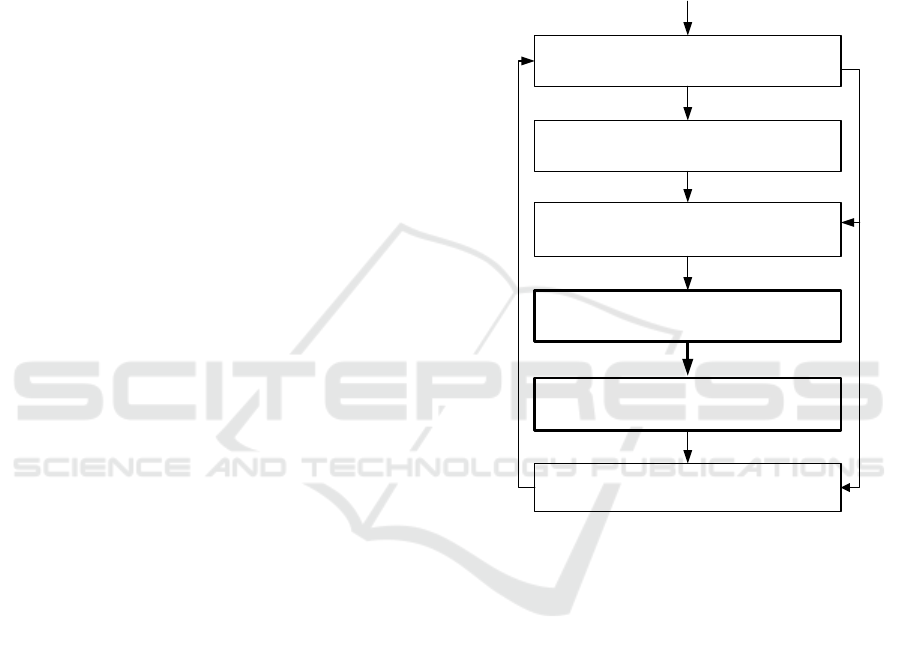
The contribution of this paper is shown in Figure 5
as boxes 3 and 4. Our algorithms form parts of the
Protocol Model-Based testing tool chain, that we are
going to apply for Case Management Systems.
1.Protocol Model with CallBacks
3.Object Model Generation
by parsing of the prepared Protocol Model
(contribution of this paper)
2. Protocol Model Preparation
(connected forms, instances)
4.Test Generation
(contribution of this paper)
5.Test Execution.
Analysis of the Test Execution
Set of Requirements
Figure 5: Protocol Model-Based Testing Methodology.
In future work we are also considering the follow-
ing research directions:
(1) Partitioning a protocol model into the groups
of independent protocol machines with disjoint sets
of recognised events. The theory of Protocol Mod-
elling identifies the trace-independent protocol ma-
chines and has a proof of observational consistency
for them (McNeile and Roubtsova, 2008). Thus, the
independent sets of protocol machines should result in
independent sets of traces. Each such a group of pro-
tocol machines can be used to produce related tests
which can be tested separately. This would again fa-
cilitate the reduction of testing effort if any of such
sets change. In future work we will present our al-
gorithm of partitioning of protocol machines and the
methods for selection of a test strategy using parti-
tioning of protocol machines.
(2) Automation of the model preparation and pro-
duction of test scripts from our test traces. Un-
A Test Generator for Model-Based Testing
111

like other modeling methods, the protocol modeling
makes use of callbacks that calculate data and states.
Running the callbacks during the process of the gen-
eration of tests scripts from the test traces, generation
of which is described in this paper, we are going to
build executable tests.
REFERENCES
Aalst van der, W. and Weske, M. (2005). Case Handling: a
new paradigm for business process support. Data &
Knowledge Engineering, 52(2):129–162.
Bracha, G. and Cook, W. (1990). Mixin-based inheri-
tance. OOPSLA/ECOOP ’90 Proceedings of the Eu-
ropean conference on object-oriented programming
on Object-oriented programming systems, languages,
and applications, pages 303–311.
Davenport, T. and Nohria, N. (1994). Case Management
and the Integration of Labor. Sloan Management Re-
view.
Greenyer, J., Rieke, J., Travkin, O., and Kindler, E. (2008).
TGGs for Transforming UML to CSP: Contribution to
the ACTIVE 2007 Graph Transformation Tools Con-
test. University of Paderborn,Technical Report tr-ri-
08-287.
Hanenberg, S., Stein, D., and Unland, R. (2007). From
aspect-oriented design to aspect-oriented programs:
tool-supported translation of JPDDs into code. In
AOSD, pages 49–62.
Hoare, C. (1985). Communicating Sequential Processes.
Prentice-Hall International.
Kervinen, A., Maunumaa, M., P
¨
a
¨
akk
¨
onen, T., and Katara,
M. (2006). Model-Based Testing Through a GUI.
volume 3997 of Lecture Notes in Computer Science,
pages 16–31.
McNeile, A. and Roubtsova, E. (2008). CSP parallel com-
position of aspect models. AOM’08, pages 13–18.
McNeile, A. and Roubtsova, E. (2009). Composition Se-
mantics for Executable and Evolvable Behavioural
Modeling in MDA. BM-MDA’09,ACM DL:ISBN:
978-1-60558-503-1, pages 1–8.
McNeile, A. and Roubtsova, E. (2012). Motivation and
guaranteed completion in workflow. LNBIP, 142:16–
42.
McNeile, A. and Simons, N. (2000). http://www.metama-
xim.com/.
McNeile, A. and Simons, N. (2006). Protocol Modelling.
A Modelling Approach that Supports Reusable Be-
havioural Abstractions. Software and System Model-
ing, 5(1):91–107.
Myers, G. (2004). The Art of Software Testing. Wiley.
OMG (2003). Unified Modeling Language: Superstructure
version 2.1.1 formal/2007-02-03.
OMG (2013). Case Management Model
and Notation (CMMN). FTF Beta 1.
http://www.omg.org/spec/CMMN/121101.
Petri, C. and Reisig, W. (2008). Petri net, volume 3. Schol-
arpedia: 3(4):6477.
Roubtsova, E. and Kuiper, R. (2003). Process Semantics
for UML Component Specifications to Assess Inheri-
tance. Electr. Notes Theor. Comput. Sci., 72(3):145–
159.
UML (2005). Testing profile. formal/05-07-07,Version 1.0.
Watkins, J. and Simon, M. (2010). Testing IT. 2nd ed. Cam-
bridge University Press.
Fourth International Symposium on Business Modeling and Software Design
112
