
Electromagnetic Linear Micro Drives for Braille Screen:
Characteristics, Control and Optimization
Dimitar N. Karastoyanov, Lyubka A. Doukovska, and Vassia K. Atanassova
Institute of Information and Communication Technologies, Bulgarian Academy of Sciences
Acad. G. Bonchev str., bl. 2, 1113 Sofia, Bulgaria
dkarast@iinf.bas.bg; doukovska@iit.bas.bg; vassia.atanassova@gmail.com
Keywords: Linear actuators, Braille screen, Optimization, Permanent magnets, Force characteristics, Finite element
method.
Abstract: The graphical interfaces based on visual representation and direct manipulation of objects made the
adequate use of computers quite difficult for people with reduced sight. A new type graphical Braille screen
is developed. Permanent magnet linear actuator intended for driving a needle in Braille screen has been
optimized. Finite element analysis, response surface methodology and design of experiments have been
employed for the optimization. The influence of different parameters of the construction of a recently
developed permanent magnet linear electromagnetic actuator for driving a needle in a Braille screen is
discussed. The static force characteristics and magnetic field distribution is studied when varying the
parameters.
1 INTRODUCTION
Permanent magnets have been intensively used in the
constructions of different actuators in recent years.
One of the reasons for their application is the
possibility for development of energy efficient
actuators. New constructions of permanent magnet
actuators are employed for different purposes. One
such purpose is the facilitation of perception of
images by visually impaired people using the so
called Braille screens.
Recently, different approaches have been utilized
for the actuators used to move Braille dots (Nobels, et
al., 2002; Cho, et al., 2006; Hernandez, et al., 2009;
Green, et al., 2006; Chaves, et al., 2009; Kwon, et al.,
2008; Kato, et al., 2005; Kawaguchi, et al., 2010). A
linear magnetic actuator designed for a portable
Braille display application is presented in (Nobels, et
al., 2002). Actuators based on piezoelectric linear
motors are given in (Cho, et al., 2006; Hernandez, et
al., 2009). A phase-change microactuator is presented
in (Green, et al., 2006) for use in a dynamic Braille
display. Similar principle is employed in (Chaves, et
al., 2009), where actuation mechanism using metal
with a low melting point is proposed. In (Kwon, et al.,
2008), Braille code display device with a poly-
dimethylsiloxane membrane and thermopneumatic
actuator is presented. Braille sheet display is presented
in (Kato, et al., 2005) and has been successfully manu-
factured on a plastic film by integrating a plastic sheet
actuator array with a high-quality organic transistor
active matrix. A new mechanism of the Braille display
unit based on the inverse principle of the tuned mass
damper is presented in (Kawaguchi, et al., 2010).
Different electromagnetic actuators have been
studied by the authors in (Yatchev, et al., 2011c;
Karastoyanov, 2010; Karastoyanov, Simeonov, 2010;
Karastoyanov, Simeonov, et al., 2010; Karastoyanov,
Yatchev, et al., 2011).
In the present paper, recently developed permanent
magnet linear actuator for driving a needle (dot) in
Braille screen is studied and its magnetic field and
static force-stroke characteristics have been obtained
using the finite element method (Yatchev, et al.,
2011a; Yatchev, et al., 2011b).
2 ACTUATOR CONSTRUCTION
The principal actuator construction is shown in
Figure 1. The moving part is axially magnetized
cylindrical permanent magnet.
The two coils are connected in series in such way
that they create magnetic flux of opposite directions in
88
Karastoyanov D., Doukovska L. and Atanassova V.
Electromagnetic Linear Micro Drives for Braille Screen: Characteristics, Control and Optimization.
DOI: 10.5220/0005421700880093
In Proceedings of the Third International Conference on Telecommunications and Remote Sensing (ICTRS 2014), pages 88-93
ISBN: 978-989-758-033-8
Copyright
c
2014 by SCITEPRESS – Science and Technology Publications, Lda. All rights reserved
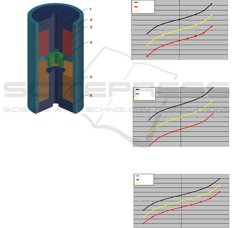
the region of the permanent magnet. In this way,
depending on the polarity of the power supply, the
permanent magnet will move either up or down.
When motion up is needed, the upper coil should
create flux in the air gap coinciding with the flux of
the permanent magnet. Lower coil at the same time
will create opposite flux and the permanent magnet
will move in upper direction. When motion down is
needed, the polarity of the power supply is reversed.
The motion is transferred to the Braille dot using
non-magnetic shaft, not shown in Figure 1.
Figure 1: Principal construction of the studied actuator. 1 –
upper core; 2 – outer core; 3 – upper coil; 4 – moving
permanent magnet; 5 – lower coil; 6 – lower core.
The actuator features increased energy efficiency,
as the need of power supply is only during the
switching between the two end positions of the
mover. In each end position, the permanent magnet
creates holding force, which keeps the mover in this
position.
3 STATIC FORCE
CHARACTERISTICS
The static force characteristics are obtained for
different construction parameters of the actuator.
The outer diameter of the core is 7 mm. The air gap
between the upper and lower core, the length of
the permanent magnet and the coils height has been
varied.
In Figures 2–5, the force-stroke characteristics
are given for different values of the permanent
magnet height hm, coil height hw, magnetomotive
force Iw and apparent current density in the coils J.
With c1 and c2, supply of the coils is denoted. The
notation “c1 = –1, c2 = 1” means supply for motion
up; “c1 = 1; c2 = –1” means supply for motion
down, while “c1 = 0, c2 = 0” means no current in the
coil, i.e. this is the force due only to the permanent
magnet.
Figure 2: Force-stroke characteristics for hm = 2mm,
δ = 3mm, hw = 5mm, Iw = 180A, J = 20А/mm
2
.
Figure 3: Force-stroke characteristics for hm = 3mm,
δ = 4mm, hw = 5mm, Iw = 180A, J = 20А/mm
2
.
Figure 4: Force-stroke characteristics for hm = 4mm,
δ = 5mm, hw = 5mm, Iw = 90A, J = 10А/mm
2
.
-1.2
-1
-0.8
-0.6
-0.4
-0.2
0
0.2
0.4
0.6
0.8
1
1.2
-0.6 -0.4 -0.2 0 0.2 0.4 0.6
F, N
x, mm
Вариант NV3a (с външен магнитопровод и с горна и долна шайби при височина на ПМ hm=2 mm и
въздушна междина δ =3 mm, hw=5mm, Iw=180, J=20А/mm2
c1=-1,c2=1
c1=1,c2=-1
c1=0,c2=0
-1.2
-1
-0.8
-0.6
-0.4
-0.2
0
0.2
0.4
0.6
0.8
1
1.2
-0.6 -0.4 -0.2 0 0.2 0.4 0.6
F, N
x, mm
Вариант NV3a (с външен магнитопровод и с горна и долна шайби при височина на ПМ hm=3 mm и
въздушна междина δ =4 mm, hw=5mm, Iw=180, J=20А/mm2
c1=-1,c2=1
c1=1,c2=-1
c1=0,c2=0
-1.2
-1
-0.8
-0.6
-0.4
-0.2
0
0.2
0.4
0.6
0.8
1
1.2
-0.5 -0.4 -0.3 -0.2 -0.1 0 0.1 0.2 0.3 0.4 0.5
F, N
x, mm
Вариант NV3a (с външен магнитопровод и с горна и долна шайби при височина на ПМ hm=4 mm и
въздушна междина δ =5 mm, hw=5mm, Iw=90, J=10А/mm2
c1=-1,c2=1
c1=1,c2=-1
c1=0,c2=0
Electromagnetic Linear Micro Drives for Braille Screen: Characteristics, Control and Optimization
89
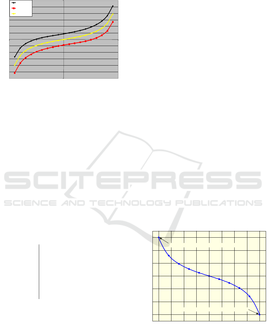
Figure 5: Force-stroke characteristics for hm = 2mm,
δ = 5mm, hw = 10mm, Iw = 180A, J = 10А/mm
2
.
As seen, the major part of the characteristics is
suitable for Braille screen application.
4 OPTIMIZATION
The objective function is minimal magneto motive
force of the coils. The optimization parameters are
dimensions of the permanent magnet, ferromagnetic
discs and the cores. As constraints, minimal electro-
magnetic force acting on the mover, minimal starting
force and overall outer diameter of the actuator
have been set. The optimization is carried out
using sequential quadratic programming, (Yatchev,
Karastoyanov, 2012).
The canonic form of the optimization problem is:
min{NI}
5
0.5
0.3
0 25 / 2
0.3
0.05
hw
hm
hd
J A mm
Fh N
Fs N
where:
NI — ampere-turns — minimizing energy con-
sumption with satisfied force requirements;
Fh — holding force — mover (shaft) in upper
position, no current in the coils;
Fs — starting force — mover (shaft) in upper or
lower position and energized coils;
J — coils current density;
hw, hm, hd — geometric dimensions.
Minimization of magneto-motive force NI is direct
subsequence of the requirement for minimum energy
consumption.
Constraints for Fs and Fh have already been
discussed. The lower bounds for the dimensions are
imposed by the manufacturing limits and the upper
bound for the current density is determined by the
thermal balance of the actuator.
The radial dimensions of the construction
are directly dependent by the outer diameter of the
core – D which fixed value was discussed earlier.
The influence of those parameters on the behavior of
the construction have been studied in previous
works, that make clear that there is no need radial
dimensions to be included in the set of optimization
parameters.
The optimization is carried out by sequential
quadratic programming. The optimization results are
as follows:
NI
opt
= 79.28 A,
hw
opt
= 5 mm,
hm
opt
= 2.51 mm,
hd
opt
= 1.44 mm,
J
opt
= 19.8 A
The optimal parameters were set as input values
to the FEM model. The force-stroke characteristics
of the optimal actuator are shown in Figures 6 and 7.
In Figures 8 and 9, the magnetic field of the
optimal actuator is plotted for two cases.
Figure 6: Force-stroke characteristic of the optimal
actuator. The force is created by the permanent magnet
only (no current in the coils).
-1.2
-1
-0.8
-0.6
-0.4
-0.2
0
0.2
0.4
0.6
0.8
1
1.2
-1 -0.5 0 0.5 1
F, N
x, mm
Вариант NV3a (с външен магнитопровод и с горна и долна шайби при височина на ПМ hm=4 mm и
въздушна междина δ =6 mm, hw=5mm, Iw=90, J=10А/mm2
c1=-1,c2=1
c1=1,c2=-1
c1=0,c2=0
-0.4 -0.3 -0.2 -0.1 0 0.1 0.2 0.3 0.4
-0.3
-0.2
-0.1
0
0.1
0.2
0.3
x, mm
Fh, N
Optimal force-stroke characteristic (no current in the coil)
Fh - holding force in upper position of the shaft
Fh - holding force in lower position of the shaft
Third International Conference on Telecommunications and Remote Sensing
90
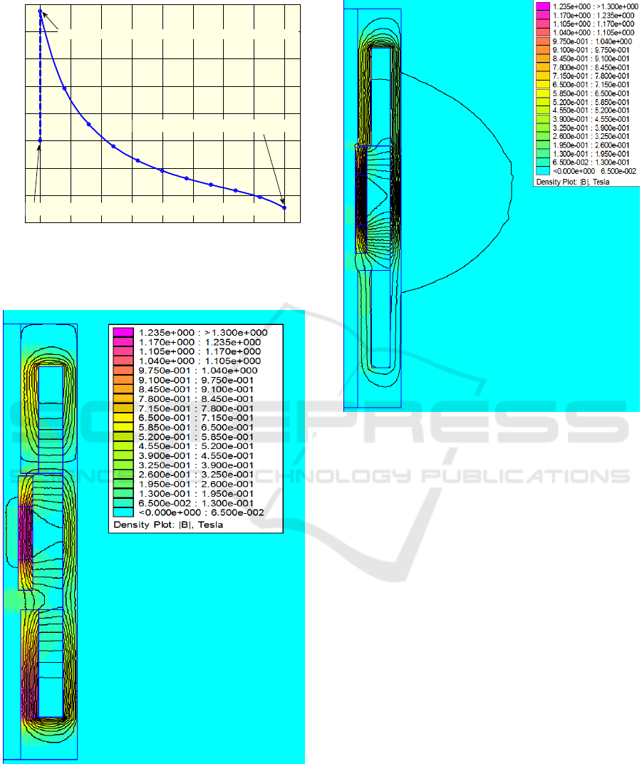
Figure 7: Force-stroke characteristic of the optimal
actuator. Coils are energized. The shaft is displaced from
final upper to final lower position.
Figure 8: Magnetic field of the optimal actuator with shaft
in upper position and coils energized to create downward
force.
Figure 9: Magnetic field of the optimal actuator with no
current in the coils.
The force constraints for Fs and Fh are active
which can be expected when minimum energy con-
sumption is required. The active constraint for hw is
also expected because longer upper and lower cores
size which respectively means longer coils will
increase the leakage coil flux and corrupted coil
efficiency.
5 CONTROL
The developed actuator has static force character-
istics which are suitable for Braille screen app-
lication, as illustrated on Figure 10.
The employed approach has confirmed its robust-
ness for solution to the optimization problem for the
actuator. The obtained optimal solution satisfies the
requirements for actuators for Braille screen. The
presented variant of the linear electromagnetic
actuator is energy efficient because of the impulse
way of its work, (Balabozov, et al., 2012). All the
three varied parameters influence the characteristics
and especially the initial force, which is significant
for these actuators.
-0.4 -0.3 -0.2 -0.1 0 0.1 0.2 0.3 0.4
0
0.1
0.2
0.3
0.4
0.5
0.6
0.7
0.8
x, mm
F, N
FORCE-STROKE characteristic (energized coils)
Fh - force switches to the holding force when current is ceased
F - final force (shaft imoved in lower position, coils still energized)
Fs - starting force (shaft in upper position)
Electromagnetic Linear Micro Drives for Braille Screen: Characteristics, Control and Optimization
91
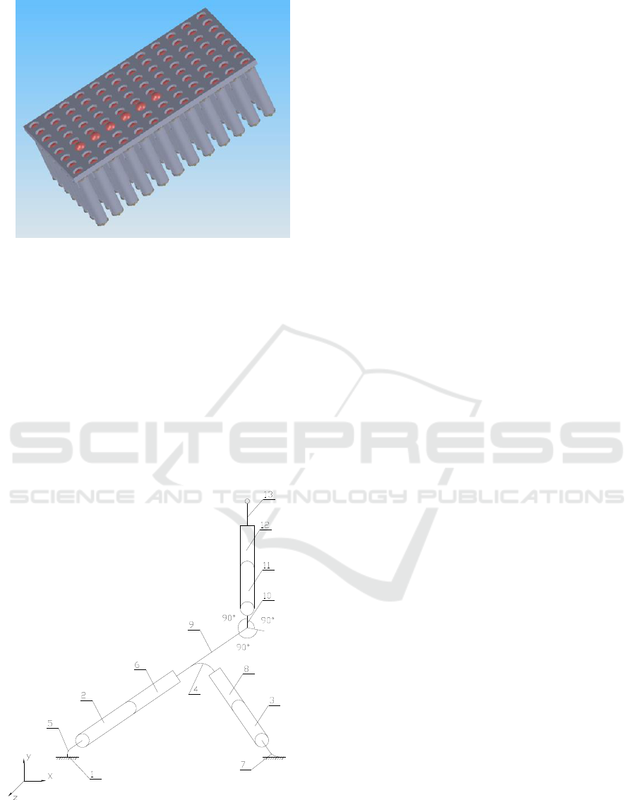
Figure 10: Braille screen with needles (dots) driven by
linear actuators.
For better resolution of the graphical images the
Braille screen must be larger, for example 96×64
linear micro drives (pixels). It is more than 6000
elements in human hand size with 4 coil connectors
for each. In this case we need a strong electro-
mechanical test of the entire circuit. We plan to use
micro robots for positioning and testing, (Georgiev,
et al., 2010; Genova, et al., 2010; Kotev, et al.,
2011). We develop a smart micro robot with 3 DOF
and piezo effectors, shown on Figure 11.
Figure 11: Micro manipulator with 3 degree of freedom
and piezo effectors, where: 1 – base; 2, 3, 11 – mobile
links; 4, 5, 7 – elastic connections; 6, 8, 12 – piezo
actuators; 9, 10 – hard connections; 13 – sensing element.
6 CONCLUSION
Based on the results obtained the following con-
clusions can be drawn:
The developed actuator has static force character-
istics which are suitable for Braille screen
application;
Increasing the height of the coil has important
influence on the force-displacement character-
istics and the holding force. Above a certain
value, thought, further increase does not lead to
significant change;
The maximal stroke influences more significantly
the initial force than the holding one and its
minimal value could be recommended;
Higher outer diameter of the actuator leads to
significant increase of both holding and initial
force;
Current density of 15 A/mm2 could ensure
enough initial force at lower starting position of
the mover.
ACKNOWLEDGEMENTS
The research work reported in the paper is partly
supported by the project AComIn “Advanced
Computing for Innovation”, grant 316087, funded by
the FP7 Capacity Programme (Research Potential of
Convergence Regions).
REFERENCES
Balabozov I., I. Yatchev, K. Hinov, D. Karastoyanov,
Influence of Different Factors on The Static Force
Characteristics of a Permanent Magnet Linear Actuator
for Braille Screen, SIELA 2012, May 28-30 2012,
Bourgas, Bulgaria, vol. 2, 20–26.
Chaves D., I. Peixoto, A.C.O. Lima, M. Vieira, C. J. de
Araujo, Microtuators of SMA for Braille display
system. IEEE International Workshop on Medical
Measurements and Applications. MeMeA 2009, 64–
68.
Cho H. C., B. S. Kim, J. J. Park, J. B. Song, Development
of a Braille Display using Piezoelectric Linear Motors.
International Joint Conference SICE-ICASE, 2006,
1917–1921.
Hernandez H., E. Preza, R. Velazquez, Characterization of
a Piezoelectric Ultrasonic Linear Motor for Braille
Displays. Electronics, Robotics and Automotive
Mechanics Conference CERMA 2009, 402–407.
Georgiev G., V. Kotev, T. Tiankov, Accuracy and
calibration of micropositioning robotic Systems.,
Journal ACTA Technica corviniensis – Bulletin of
Third International Conference on Telecommunications and Remote Sensing
92

engineering, Fascicule 3, July – September, tome III,
2010, 125–130.
Genova P., V. Kotev, F. Ionescu, K. Kostadinov, Linkage
mechanisms with piezo- structured ceramic actuators.,
Proceedings of 2010 International Conference on
Optimisation of the Robots and Manipulators,
Calimanesti, Romania, 28–30 May, 2010, 211–214.
Green S., B. Gregory, N. Gupta, Dynamic Braille Display
Utilizing Phase-Change Microactuators. 5th IEEE
Conference on Sensors, 2006, 307–310.
Karastoyanov D., Braille screen, Bulgarian Patent
announce No 110731, 10.08.2010.
Karastoyanov D., S. Simeonov, Braille display, Bulgarian
Patent announce No 110794, 11.11.2010.
Karastoyanov D., S. Simeonov, A. Dimitrov, Braille
display, Bulgarian Patent announce No 110795,
11.11.2010.
Karastoyanov D., I. Yachev, K. Hinov, T. Rachev, Braille
screen, Bulgarian Patent announce No 111055,
13.10.2011.
Kato Y. et al., A flexible, lightweight Braille sheet display
with plastic actuators driven by an organic field-effect
transistor active matrix. IEEE International Electron
Devices Meeting, 2005.
Kawaguchi Y., K. Ioi, Y. Ohtsubo, Design of new Braille
display using inverse principle of tuned mass damper.
Proceedings of SICE Annual Conference 2010, 379–
383.
Kotev V., K. Kostadinov, P. Genova, Design of incur-
porated macro-micro robots for macro and micro
operations., 8th Int. Conference on Informatics in
Control, Automation And Robotics (ICINCO 2011),
28-31 July 2011, Noordwijkerhout, The Netherlands.
Proceedings ICINCO 2011, vol. 2, 2011, 273–276.
Kwon H.-J., S. W. Lee, S. S. Lee, Braille code display
device with a PDMS membrane and thermopneumatic
actuator. 21st IEEE International Conference on Micro
Electro Mechanical Systems MEMS 2008, 527–530.
Nobels T., F. Allemeersch, K. Hameyer, Design of a High
Power Density Electromagnetic Actuator for a Portable
Braille Display. International Conference EPE-PEMC
2002, Dubrovnik & Cavtat, 2002.
Yatchev I., D. Karastoyanov, Optimization of Permanent
Magnet Linear Actuator for Braille Screen.,
International Symposium IGTE 2012, September 16-
18, 2012, Graz, Austria, 59–63.
Yatchev I. et al. Finite element modelling of electro-
magnets for Braille screen. Proceedings of PES 2011
Conference, Nis, Serbia, 2011.
Yatchev I., et al. Force characteristics of an electromagnet-
tic actuator for Braille screen, Proceedings of
International Conference on Electrical Machines,
Drives and Power Systems ELMA 2011, 21-22 October
2011, Varna, Bulgaria, 338–341.
Yatchev I. et al. Static force characteristics of electro-
magnetic actuators for Braille screen. Facta
Universitatis, Ser.: Elec. Energ. vol. 24, No. 2, August
2011, 157–167.
Electromagnetic Linear Micro Drives for Braille Screen: Characteristics, Control and Optimization
93
