
Experimental Evaluation of a Modified Obstacle Based Potential Field
Algorithm for an Off-road Mobile Robot
Rickard Nyberg, George Nikolakopoulos and Dariusz Kominiak
Control Engineering Group, Department of Computer Science, Electrical and Space Engineering,
Lule
˚
a University of Technology, Lule
˚
a, Sweden
Keywords:
Off Road Mobile Robot, Artificial Potential Fields, Visual Feedback, Depth Image, Obstacle Detection.
Abstract:
This article presents an experimental evaluation of a modified obstacle based artificial potential field algorithm
for an off-road mobile robot. The first contribution of the presented approach concerns the transformation
of the artificial potential field method for the guidance of the vehicle and obstacle avoidance, in order to
make it suitable for utilising a visual feedback. The visual feedback is relying on a depth image, provided
by the low cost kinect sensor. The second contribution concerns the proposal of a novel scheme for the
identification and perception of obstacles. Based on the proposed methodology, the vehicle is capable of
categorising the obstacles based on their height in order to alter the calculated forces, for enabling a cognitive
decision regarding their avoidance or the driving over them, by utilising the robot’s off road capabilities.
The proposed scheme is highly suggested for off road robots, since in the normal cases, the existence of
small rocks, branches, etc. can be accidentally identified as obstacles that could make the robot to avoid
them or block its further movement. The performance of the proposed modified potential field algorithm has
been experimentally applied and evaluated in multiple robotic exploration scenarios, where from the obtained
results the efficiency and the advantages of such a modified scheme have been depicted.
1 INTRODUCTION
Autonomous off-road vehicles have a vast variety of
potential applications in a lot of different domains
such as exploration, search and rescue, environmen-
tal management and forest machinery. Transforming
an off–road vehicle into fully autonomous to reliably
navigate and avoid obstacles, still remains a major
challenge in robotics. To complete such a vision, a
mobile robot system needs to be equipped with reli-
able sensors to percept the environment, build envi-
ronmental maps and planning safe paths through the
cruising terrain, while it would be ideal if the onboard
sensors and perception systems would be able to han-
dle very rugged and uneven terrains. An ability which
comes in contrast to the more conventional robotic
systems, being operated in simpler and more struc-
tured environments.
One of the main problems in off-road vehicle nav-
igation is obstacle detection and avoidance, mainly
due to the wide diversity of appearance of potential
obstacles, different shapes and varying height that
make this problem very challenging. In the related
scientific literature, several approaches have been pro-
posed to address these problems. In some cases, the
focus have been more towards designing special off-
road robotic platforms, instead of focusing on au-
tonomous navigation. Such an example is the rover
Shrimp presented in (Siegwart et al., 2002), which is
a six-wheeled rover with a special spring suspension
to guarantee optimal ground contact of all wheels at
any time. Another example is the HELIOS-VI(Hirose
et al., 2001), a terrain adaptive crawler. Many efforts
have tried to solve the problem relying on several sen-
sors, including laser range finder and radar (Matthies
et al., 1995), while other approaches include the uti-
lization of stereo vision technique (Broggi et al.,
2005). Active sensors make the problem consider-
ably easier, but there are always a trade off in cost and
power consumption. In the area of image process-
ing for robotic guidance, there has been a tremendous
growth in the latest years. Some indicative research
efforts have been reported in (Zhang et al., 2010),
where a visual SLAM algorithm has been introduced
that utilizes stereo vision to estimate a 3D map repre-
sentation of the environment. The research in (Vala-
vanis et al., 2000) presents a method for vision guided
navigation for non-holonomic robots, by using only
626
Nyberg R., Nikolakopoulos G. and Kominiak D..
Experimental Evaluation of a Modified Obstacle Based Potential Field Algorithm for an Off-road Mobile Robot.
DOI: 10.5220/0005121006260633
In Proceedings of the 11th International Conference on Informatics in Control, Automation and Robotics (ICINCO-2014), pages 626-633
ISBN: 978-989-758-040-6
Copyright
c
2014 SCITEPRESS (Science and Technology Publications, Lda.)

quantities that can be directly measured in the image
and thus bypassing the pose estimation phase. Other
research groups used image processing to control a
robot to stay on a desired path (Schlengel et al., 1997).
Image processing has also been used for exploration
purposes, where the robot is driven towards areas that
are informative for navigation by utilizing a monocu-
lar pan-tilt camera.
In the area of obstacle avoidance and guidance in
exploration robotic tasks, one of the most popular and
experimentally applied method is the one of the Arti-
ficial Potential Fields (APF) (Khatib, 1986), while a
lot of modifications and improvements can be located
in (Guo et al., 2013) and (Vadakkepat et al., 2000).
The main contribution of this article is dual. First the
transformation of the APF method to make it suitable
for utilizing visual feedback will be presented. Un-
til now, it should be highligted that the majority of
the APF implementations utilize sonar sensors or in-
fra red sensors to measure only the distance to obsta-
cles. With visual feedback and a camera as a sensor
it is possible to retrieve more information about the
environment and the obstacles, while increasing the
sensing robustness and the overall flexibility of the
robotic platform. Secondly, a novel scheme for iden-
tification and perception of obstacles, which not only
considers the distance to the obstacles but also their
height, will be presented. The cognitive categorisa-
tion of obstacles will feed the APF scheme, while di-
rectly affecting the guidance of the vehicle in order to
overcome small obstacles.
This article is structured as it follows. Section ??
presents the basic theory of the APF method and es-
tablishes the image processing algorithm for identify-
ing and measuring obstacles based on depth images.
In Section 3, the modification of the APF based on
the kinematic model of the robot and on the identi-
fied height of obstacles will be presented. The overall
experimental setup and an overview of the suggested
overall modified APF will be presented in Section 4.
The evaluation of the proposed methodology is being
performed by multiple experimental scenarios, pre-
sented in Section 5, while the conclusions are drawn
in Section 6.
2 OBSTACLE DETECTION AND
AVOIDANCE
2.1 Artificial Potential Fields
The basic principle behind the APF methodology is
that obstacles that should be avoided, are surrounded
by repulsive potentials, while the goal point is sur-
rounded by an attractive potential. As a result, the
robot at the q–point will navigate in the direction of
the resulting force U, computed by summing the set
of all the repulsive forces U
rep
, with the set of all the
attractive forces U
att
as:
U(q) = U
att
(q) +U
rep
(q)
For computing the repulsive and attractive potentials,
U
att
(q) and U
rep
(q), multiple methods can be found
in the related literature.
One popular methodology, which is the one
adopted in this research, is to measure a scaled dis-
tance to the goal, U(q) = ζd(q,q
goal
) with ζ the scal-
ing factor, utilized to scale the effect of the attractive
potential, and thus the attractive force can then be ex-
pressed as (Choset et al., 2005):
U
att
=
1
2
ζd
2
(q, q
goal
),
while the gradient becomes:
∇U
att
(q) = ∇(
1
2
ζd
2
(q, q
goal
)) = ζd(q − q
goal
)
and thus in this case, if the robot starts at any point,
other than the goal, and by following the negative gra-
dient, it will follow a path to the goal. A combination
of the quadratic and conic potential is utilized to es-
cape the problem, which the quadratic potential can
generate, to high velocities close to the goal, as fol-
lows (Choset et al., 2005):
U
att
(q) =
1
2
ζd
2
(q, q
goal
), d(q, q
goal
) ≤ d
∗
goal
d
∗
goal
ζd(q, q
goal
) −
1
2
ζ(d
∗
goal
)
2
, d(q, q
goal
) > d
∗
goal
.
where the gradient is defined by:
∇U
att
(q) =
(
ζd(q − q
goal
), d(q, q
goal
) ≤ d
∗
goal
,
d
∗
goal
ζd(q−q
goal
)
d(q,q
goal
)
, d(q, q
goal
) > d
∗
goal
,
with d
∗
goal
the threshold distance from the goal, where
the algorithm switches between conic and quadratic
potentials.
The next step is to calculate the repulsive poten-
tial. The repulsive potential keeps the robot away
from the obstacles and the strength of the repul-
sive potential depends on how close the robot is to
the obstacle. The repulsive potential is defined in
terms of distance to the closest obstacle D(q), defined
as (Choset et al., 2005):
U
rep
(q) =
1
2
η
1
D(q)
−
1
Q
∗
2
, D(q) ≤ Q
∗
,
0, D(q) > Q
∗
,
whose gradient is
∇U
rep
(q) =
(
η
1
D(q)
−
1
Q
∗
1
D
2
(q)
∇D(q), D(q) ≤ Q
∗
,
0, D(q) > Q
∗
ExperimentalEvaluationofaModifiedObstacleBasedPotentialFieldAlgorithmforanOff-roadMobileRobot
627

The utilization of the Q
∗
factor allows the robot
to ignore obstacles that are sufficiently far away, while
η can be considered as a gain on the repulsive gradi-
ent. In case that these algorithmic formulations are
being applied, it is possible to produce a path, which
it might oscillate around points that are equally distant
in both directions from the obstacles. To avoid these
oscillations, the repulsive potential can be defined in
terms of distances to individual obstacles, instead of
just the closest obstacle. Then each obstacle has its
own potential function as (Choset et al., 2005):
U
rep
i
(q) =
1
2
η
1
d
i
(q)
−
1
Q
∗
i
2
, if d
i
(q) ≤ Q
∗
i
0, if d
i
(q) > Q
∗
i
(1)
where Q
∗
i
defines the size of the domain of influence
for obstacle i. Then the total repulsive field becomes:
n
∑
i=1
U
rep
i
(q). (2)
An significant advantage of the APF method is the
fact that it could be realised also for controlling the
velocity of the robot. In this approach, the translation
velocities (v
x
, v
y
) can be set proportional to the force
F(q) that is generated by the potential field as:
F(q) = −∇U
att
(q) − ∇U
rep
(q) (3)
An object in the physical environment often consists
of a regular shape and material. The problem in de-
tecting obstacles is how the obstacles should be dis-
tinguished from the environment, and how to deter-
mine where the obstacle begins and where the ground
begins.
2.2 Depth Image Pre-filtering Process
The depth image from the kinect is somewhat unsta-
ble and flickery, since in some regions the depth cam-
era cannot read any depth values, which are presented
as completely black regions in Fig. 2, marked by
red rectangulars. Moreover, these regions are chang-
ing over the time, a fact that causes the video to
flicker. Thus the depth sequential frames from the
kinect should be processed to filter and exclude this
flickering and also to extract the necessary informa-
tion needed for detecting obstacles. Since the kinect
gives depth values in the range 0.5m - 3m, the first
step is to filter out values larger than a certain thresh-
old. The reason for this is the fact that obstacles be-
ing far away as 3m from the robot should not have an
influence on the robot’s movement. Thus after thresh-
olding the acquired depth image is being filtered to
display values only in the region of 0.5m - 1.5m. This
Figure 1: Depth image before image processing with dead
regions marked with red squares.
filtering has also a direct effect on the processing time
due to the less data needed to be processed.
For avoiding the flickering effect, mentioned ear-
lier, a median filter has been utilized and applied
through every depth image acquisition, where is im-
age entry is being replaced by the median of the
neighbouring entries (Justusson, 1981). A compari-
son among the original sampled depth image and af-
ter the application of the median filtering is being pre-
sented in Fig. 2.
Figure 2: Depth image before (left) and after (right) image
processing.
Finally to determine where an obstacle boarder
begins and ends edge detection can be used. The
detection is made by identifying points in the depth
image frames, where the brightness changes sharply.
The edge detection algorithm used in this research is
the Canny edge detection (Francis, 1983).
2.3 Depth Image based APF
Often, when the APF method is implemented on mo-
bile robots, the sensor used is some type of dis-
tance sensor; sonar or laser range (Kalmegh et al.,
2010),(Sercan and Hakan, 2011), while very little
work has been done where the APF method is im-
plemented with a camera as a sensor. With this type
of imaging sensor, new problems arise during the im-
plementation of the APF method. Since the camera
faces forward in the robots moving direction, the an-
gles to all the obstacles is harder to obtain. Also since
the depth data are filtered and only obstacles in the
desired region can be seen, the depth values of the
open regions between obstacles can not be taken into
account when calculating the forces.
ICINCO2014-11thInternationalConferenceonInformaticsinControl,AutomationandRobotics
628

The first step in implementing the APF with a
depth camera is to determine a Region Of Interest
(ROI). This will make the image processing faster,
while the robot does not have to consider the whole
environment, but only an important part of it. The
ROI should be selected in a way such that the robot
can detect relevant obstacles and not loose too much
information about its surroundings and thus a trade
off should be applied. The kinect sensor provides the
depth values as the distance from an imaginary plane,
going through the kinect, and this z-value can then be
used as r
y
, while the the x-value can be utilized as r
x
.
The robots direction of movement is then calculated
by applying (3) to each pixel in the ROI and then each
force component is summed up to result in the overall
force vector F
res
in which the robot should move. The
left and right wheel speeds are determined by normal-
izing the resulting force vector as:
ˆ
F
res
=
F
res
||F
res
||
(4)
The resulting force vector will then end up on a cir-
cle with maximum radius equal to one. If the result-
ing force is pointing at 90
◦
the robot should move
straight forward and with a force pointing at 0
◦
, the
robot should turn right in-place and between theses
extremes do varying degrees of turning.
3 NAVIGATION BASED ON
MODIFIED APF
In the presented approach it is assumed that the robot
knows neither the map of the environment nor the
start or goal position (free exploration mission). This
introduces a problem when it comes to calculating the
attractive potential. Since there is no point that at-
tracts the robot, the attractive potential must be based
on something else than a goal position. This can be
solved by making the robot attracted by open spaces,
or equivalently distance measurements greater than
a certain threshold value are considered as attractive
forces to the robot. With this approach in mind, the
force in (3) can be rewritten as (Kalmegh et al., 2010):
F
i
= k
1
t
2
−
1
|r
θ
|
2
· ˆr
θ
, (5)
where t is the threshold distance. Equation (5) is the
force produced by the measured distance r
θ
, and if r
θ
is larger than the threshold distance the force becomes
attractive and the opposite occurs if r
θ
is smaller than
the threshold. The total force is then the sum of all
the forces:
F
tot
= k
2π
∑
θ=0
1
t
2
−
1
|r
θ
|
2
· ˆr
θ
, (6)
where:
r
θ
=
r
x
r
y
=
r · cos θ
r · sin θ
. (7)
and
|r
θ
|
2
= r
2
x
+ r
2
y
(8)
ˆr
θ
=
r
θ
||r
θ
||
. (9)
Equations (8), (9) are then used together with equa-
tion (6) to calculate the total force vector acting on
the robot. The robot is then steered in the direction of
the resulting force, and driving with a velocity propor-
tional to the magnitude of the force, while the overall
concept is presented in Figure 3.
Figure 3: Basic principle of APF method with attraction to
open spaces.
3.1 Kinematic model of the robot
In this research effort, the robot is considered as a
rigid body on wheels, operating on a horizontal plane.
The position of the robot can be expressed as vector,
q, with respect to the global reference frame as(Sercan
and Hakan, 2011):
q
I
=
x y θ
T
Where x, y and θ represents the position and orienta-
tion of the robot respectively. The transformation be-
tween the local velocities and the generalized veloci-
ties can be calculated as(Sercan and Hakan, 2011):
˙x
˙y
˙
θ
=
cos(θ) sin(θ) 0
−sin(θ) cos(θ) 0
0 0 1
v
x
v
y
ω
(10)
while, for preventing lateral slip, the following non-
holonomic constraints must be applied as:
v
y
− ω · d = 0 (11)
[
sin(θ) cos(θ) −d
] ·
˙
X
˙
Y
˙
θ
T
= A(q) ˙q = 0
(12)
where d is defined as the distance between the
robots center of mass and center of geometry. Then
(10) can be rewritten as:
˙q = S(q) · u (13)
ExperimentalEvaluationofaModifiedObstacleBasedPotentialFieldAlgorithmforanOff-roadMobileRobot
629

S(q) =
cos(θ) −d sin(θ)
sin(θ) d cos(θ)
0 1
, u =
v
x
ω
T
(14)
Which represents the kinematic model of the robot
with u the control input.
3.2 Height Measurement
With a camera as a sensor it is quite straight forward
to obtain the height of an object in the field of view,
with the help of some basic geometry.
Image plane
P
C
f
Y
y
Z
Figure 4: Definitions of image and real world coordinated.
From Figure 3 and the utilization of similar trian-
gles principle the following relationships can be ob-
tained as:
y
f
=
Y
Z
−→ Y = Z ·
y
f
(15)
where f is the focal length obtained from camera cal-
ibration, y is the y-coordinate of point P, Y is the real
world y-coordinate of point P and Z is the depth value
of point P. Both f and y are in pixels and Z is given
in meters. With equation (4.32) it is possible to de-
termine the real world height of an object in the field
of view. To simplify the calculations, only the height
of the closest obstacle is considered. A scenario that
can cause problems, even though the obstacle might
be low enough for the robot to pass over, is when the
whole obstacle appears between the wheels as illus-
trated in Fig. 5.
When both points P
1
and P
2
are inside the danger
zone, the robot should avoid the obstacle. By extract-
ing the depth value to the obstacles center point, from
the depth sequential frames, (7) can be utilized to cal-
culate the repulsive force generated by the obstacle
and the robot can safely avoid it.
4 EXPERIMENTAL SETUP
The platform used in this research is a robotic vehicle
called ”Wild Thumper” (WT). This platform is spe-
Figure 5: Danger zone for obstacles.
cially made to drive in rough environments. The WT
has big wheels with very rough patterning, and it has
four DC-motors, one for each wheel, that makes it
possible to drive each wheel separately. This property
is useful when not all wheels are in contact with an
obstacle, since the speed on each wheel can be con-
trolled separately. The special super-twist suspension
on each wheel makes the platform good for driving in
very uneven terrain, while it guarantees that always
one wheel will be in contact with the ground.
The main processing unit on the robot is the Ar-
duino Due microcontroller. This board is based on
the Atmel SAM3X8E ARM Cortex-M3 CPU and the
main benefit of this board is the computational speed.
The motor controller board used here is the Rover 5
motor driver board for driving each motor and also
to receive the data generated from the encoders. The
communication between the main computer and the
Arduino board is done with an XBee-link. XBee is
a form factor compatible radio module that uses Zig-
Bee protocol. Two XBees are needed for this setup
for a bi-directional communication link; one mounted
on the Arduino board and one connected to the main
computer. To measure the rotational speed of the
wheels, four rotary magnetic encoders are mounted
on each motor shaft. The resolution of the encoders is
2000 pulses per revolution. All these additional elec-
tromechanical components have been properly been
mounted on the WT robot as it has been depicted in
Fig. 6.
The overall proposed modified APF algorithm is
being presented in Fig. 7. The procedure is divided
into two main parts; one in which the artificial forces
from each pixel in the ROI are calculated and one
where the artificial forces depending on the obstacle
height are calculated. The first step in both parts is to
convert the image coordinates into real world coordi-
nates and also to convert the RGB depth image into
an intensity image. To extract the correct x and z val-
ues corresponding to the ROI, a filter is used and to
eliminate the flickering a median filter is used on the
depth image. The main calculations then uses these
ICINCO2014-11thInternationalConferenceonInformaticsinControl,AutomationandRobotics
630

Kinect camera
Battery
Switch, arduino,
motorcontroller
XBee
Figure 6: Side view.
filtered x and z values and the ROI-image to calcu-
late the total resulting force. This is done by looping
through each pixel in the ROI and calculating and sav-
ing the force components. The calculations for height
requires the y values to be in pixels to be able to cal-
culate the real world height of the obstacles. A blob
analysis is made on the processed image and from this
the coordinates of the detected blobs corners are sent
to the force calculations. When the height of the clos-
est obstacle is determined the next step is to determine
if it is lower than the threshold and also if it is inside
the danger zone. Depending on if the obstacle is low
enough and if it lies inside the danger zone the force
from that obstacle is either calculated as F
height
or set
to zero. Finally, in the last step F
height
is added to
the force calculated from the ROI. The corresponding
left and right wheel speeds are sent to the Arduino via
the XBee link and directed to the motor controller,
which in turn sends the commands to the motors. The
speeds of each motor is then measured with the en-
coders and sent back to the Arduino in which an in-
ternal PI-controller is utilized for each motor speed.
Figure 7: Overall Flow Chart of the Proposed Modified
APF.
5 EXPERIMENTAL RESULTS
The evaluation of the overall proposed scheme has
been carried in experimental studies, while investigat-
ing the behaviour of the robot in different scenarios.
The first group of tests were made without consider-
ing the height of the obstacles and the second group of
tests the height consideration were added to the calcu-
lation of the APF forces in order to directly evaluate
the efficiency of the proposed scheme.
The first experimental test was carried with re-
spect to the S-shaped obstacle course as it is being
presented in Fig 8. The path of the robot was recorded
Figure 8: S-shapped obstacle position.
with odometry and is presented in Fig. 9, where the
blue rectangles represent the real obstacles. From the
Figure 9: Recorded path of robot.
obtained results it is obvious that the robot is capa-
ble of detecting properly the obstacles and transverse
towards the no obstacle-empty space. The acquired
depth images and the selected ROI and filtering pro-
cesses are sufficient capable of driving backward and
forward the robot, while once more it should be high-
lighted that the robot is not aware of the starting and
finishing goal.
ExperimentalEvaluationofaModifiedObstacleBasedPotentialFieldAlgorithmforanOff-roadMobileRobot
631
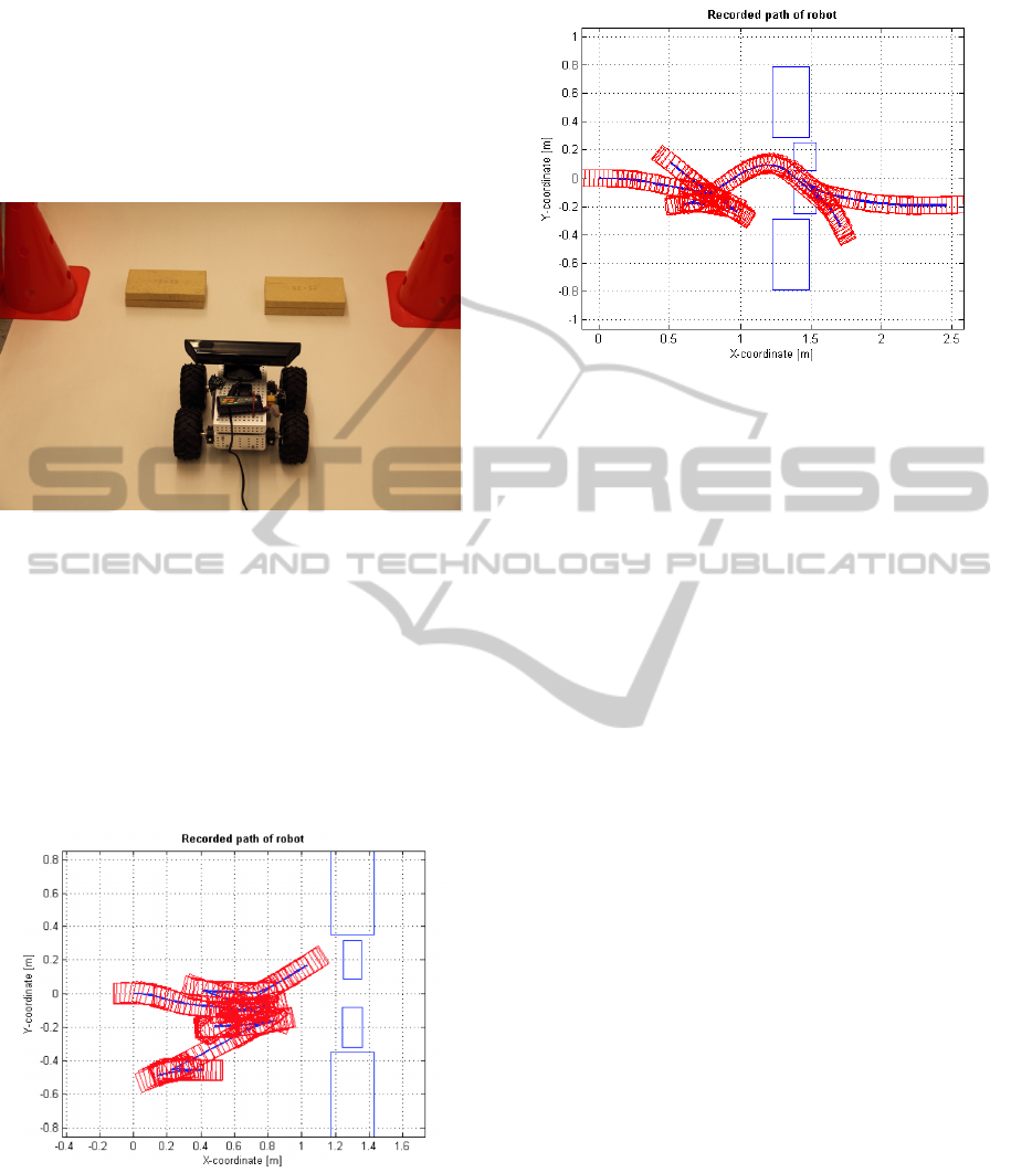
The second test was conducted in order to evalu-
ate the performance of the robot navigation, when ob-
stacles of low height have been inserted in the robots
path, as it is being presented in Fig. 10. As before,
the path of the robot has been recorded by odometry
and the results are presented in Fig. 12 from a side
view. From the obtained results it is obvious that the
Figure 10: Terrain with obstacles of various sizes.
robot, based on the supplied depth images, is able to
detect the obstacles, while is not able to recognise the
corresponding height of them and thus the robot is
performing continuous forward and backward moves,
without managing to overcome the obstacles. How-
ever, in case that the consideration of the height mea-
surement as a factor for altering the calculation of the
potential fields, as it is being presented in Fig. 12 it
is clear that the robot manages to overcome the small
scale obstacles by driving over them.
Figure 11: Recorded path of the robot for the terrain with
obstacles of various sizes, without the modified APF for
considering the height of obstacles.
In the case of off–road terrains, characterised by
numerous small obstacles, the presented modified
APF methodology would have a significant impact,
since it will enable the direct driving of the robot,
while avoiding false path alterations being initiated
Figure 12: Recorded path of the robot for the terrain with
obstacles of various sizes, with the modified APF for con-
sidering the height of obstacles.
by the existence of small scale obstacles that could be
easily ignored and bypassed by the robot.
6 CONCLUSIONS
In this article an experimental evaluation of a modi-
fied obstacle based artificial potential field algorithm
for an off-road mobile robot has been presented. The
modification relied on altering the APF algorithm in
order to make it suitable for utilising a visual feedback
and proposing a novel scheme for the identification
and perception of obstacles. Based on the proposed
methodology, the vehicle was capable of categorising
the obstacles based on their height in order to alter the
calculated forces, for enabling a cognitive decision re-
garding their avoidance or the driving over them. The
performance of the proposed modified potential field
algorithm has been experimentally applied and evalu-
ated in multiple robotic exploration scenarios, where
from the obtained results the efficiency and the advan-
tages of such a modified scheme have been depicted.
REFERENCES
Broggi, A., Caraffi, C., Fedriga, R., and Grisleri, P. (2005).
Obstacle detection with stereo vision for off-road ve-
hicle navigation. IEEE Computer Society Conference
on Computer Vision and Pattern Recognition.
Choset, H., Lynch, K., S.Hutchinson, Kantor, G., Burgard,
W., Kavraki, L., and Thrun, S. (2005). Principles
of robot motion; theory, algorithms and implementa-
tions. MIT Press.
Francis, C. J. (1983). Finding edges and lines in images.
Massachusetts Inst. of Tech. Report 1.
ICINCO2014-11thInternationalConferenceonInformaticsinControl,AutomationandRobotics
632

Guo, J., Gao, Y., and Guangzhao, C. (2013). Path planning
of mobile robot based on improved potential field. In-
formation Technology Journal, 12.
Hirose, S., Fukushima, E., Damoto, R., and Nakamoto, H.
(2001). Design of terrain adaptive versatile crawler
vehicle helios-vi. International Conference on Intelli-
gent Robots and Systems, pages 1540–1545.
Justusson, B. (1981). Median filtering: Statistical proper-
ties. Springer.
Kalmegh, S., Samra, D., and Rasegaonkar, N. (2010). Ob-
stacle avoidance for a mobile exploration robot using
a single ultrasonic range sensor. International Confer-
ence on Emerging Trends in Robotics and Communi-
cation Technologies, pages 8–11.
Khatib, O. (1986). Real-time obstacle avoidance for ma-
nipulators and mobile robots. International Journal
of Robotics Research, 5:500–505.
Matthies, L., Gat, E., Harrison, R., Wilcox, B., Volpe,
R., and Litwin, T. (1995). Mars microrover naviga-
tion: Performance evaluation and enhancement. Au-
tonomous Robots, 2:291–311.
Schlengel, N., Kachroo, P., Ball, J., and Bay, S. (1997). Im-
age based control for scaled automated vehicles. IEEE
Conference on Transportation System.
Sercan, A. and Hakan, T. (2011). Robust motion control
of a four wheel drive skid-steered mobile robot. 7th
international conference on electrical and electronics
engineering.
Siegwart, R., Lamon, P., Estier, T., Lauria, M., and Piguet,
R. (2002). Wireless sensor networks: a survey. Com-
puter Networks, 38(4):393–422.
Vadakkepat, P., T., K., and Ming-Liang, W. (2000). Evolu-
tionary artificial potential fields and their application
in real time robot path planning. Proceedings of the
2000 Congress on IEEE Evolutionary Computation,
1.
Valavanis, K., Hebert, T., Kolluru, R., and Tsouverloudis,
N. (2000). Obstacle avoidance for a mobile explo-
ration robot using a single ultrasonic range sensor.
Systems, Man and Cybernetics, Part A: Systems and
Humans, IEEE Transactions on, 30:187–198.
Zhang, T., Yi, Z., and Jingyan, S. (2010). Real-time mo-
tion planning for mobile robots by means of artificial
potential field method in unknown environment. ndus-
trial Robot: An International Journal, pages 384–400.
ExperimentalEvaluationofaModifiedObstacleBasedPotentialFieldAlgorithmforanOff-roadMobileRobot
633
