
A Stable Tracking Control of Skid Steered Mobile Platform
Seungwoo Jeon
1
, Wootae Jeong
2
and Duckshin Park
2
1
Department of Virtual Engineering, Korea University of Science and Technology, Daejeon, Korea
2
Eco-Transport Research Division, Korea Railroad Research Institute, Gyeonggi-do, Uiwang, Korea
Keywords: Mobile Platform, Skid Steering, Trajectory Tracking, Driving Control, Vehicle Control.
Abstract: The skid steering technique has been widely used in controlling mobile vehicles without steering wheels
because of light-weight and relatively simple structural configuration for steering motion control. However,
since the skid controlled mobile platform system is based on nonholonomic constraint, it is essential to
linearizing the nonlinear dynamic model of the vehicle for improving the stability of traction control.
Recently developed ventilation duct cleaning robot with moving brushing arm also utilizes the skid steering
system for traction control. Since the moving brush arm may change the mass center of the platform and
effect on dynamics consequently, a new control scheme is suggested and simulated to achieve the stable
trajectory tracking and driving motion of the developed mobile platform.
1 INTRODUCTION
Wheeled mobile platform with skid steering system
is widely used in various industrial applications
(Kanayama, Samson, Sampei et al, 1991). Skid
steering helps the mobile platform without steering
wheels to change the direction by assigning velocity
difference between two side wheels (Fukao et al,
2000). Therefore, the skid steered platform can
reduce the overall weight of the platform by
removing mechanical steering parts and reduce the
radius of rotation as well. However, due to the
nonholonomic constraints in system characteristics,
the lateral velocity of the mobile platform could not
be controlled directly by the actuator. Therefore,
many studies have been focused on linearizing the
nonlinear mobile platform model for effective
direction control based on speed difference of each
side of wheels and Instantaneous Center of Rotation
(ICR), or using various nonlinear control algorithms.
According to Shojaei et al, to remove uncertainty
caused by nonholonomic constraint in trajectory
tracking control for wheeled robot without
measuring speed, the control algorithm is presented
concerning about the actuator dynamics. Also, in
case of controlling the plant uncertainty and
unmodeled dynamics, the control law using dual
adaptive neural network algorithm has been
suggested to improve trajectory-tracking ability
(Marvin et al, 2009). Various control algorithm in
estimating contact force between tracked wheel and
the road has been studied by (Bekker, 1969) and
(Wong, 2001), whereas having the possibility of
generating error because of heavy calculation. In
addition, combined solution between kinematics and
dynamic characteristics was investigated for driving
control of wheeled robot to follow the reference path
(Caracciolo et al, 1999). In case of controlling
mobile platform with moving brush arm, the
external force model has been investigated at the
contact plane between rolling brush and cleaning
surface (Jeong et al, 2013). It was not been
considered the additional force is exerted by the
manipulator when the platform is controlled to
follow a designated path. In this paper, the control
method is suggested to stable trajectory tracking
when external force is exerted and dynamic model is
investigated with the ventilation duct cleaning robot,
which has overloaded moving arm on the platform.
2 KINEMATIC AND DYNAMIC
MODELING
Figure 1 shows the free body diagram of the mobile
platform. In the modelling, side effects by
suspensions The mobile platform has a plane motion
(moving on X-Y coordinate).
The point contact occurs between wheels
and the ground.
556
Jeon S., Jeong W. and Park D..
A Stable Tracking Control of Skid Steered Mobile Platform.
DOI: 10.5220/0005113305560561
In Proceedings of the 11th International Conference on Informatics in Control, Automation and Robotics (ICINCO-2014), pages 556-561
ISBN: 978-989-758-040-6
Copyright
c
2014 SCITEPRESS (Science and Technology Publications, Lda.)
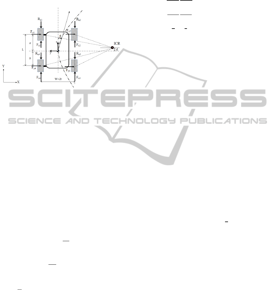
Longitudinal wheel slip is negelted.
Lateral force at the tire is generated by its
vertical load and lateral friction coefficient.
The speed of two wheels at each side are the
same.
Figure 1: A schematic model of the mobile platform on a
horizontal plane.
2.1 Dynamic Modelling of the Mobile
Platform
Based on the schematic model of the mobile
platform illustrated in Figure 1, the equation of
motion of the platform can be given by
m
,
m
,
I∅
= 2t(
,
(1)
where
is the tractive force at the contact patch of
the wheel,
is the longitudinal resistive force of
the wheel,
is the lateral force at the contact patch
of the wheel (Caracciolo et al, 1999). The resistive
force, lateral force, and resistive moment at the
Center of the Mass (CM) is calculated using friction
coefficient
(
,
) by
∑
,
(2)
∑
,
(3)
.
(4)
The dynamic model of the platform can be
expressed with generalized coordinates, q
X,Y,∅
, and matrix form as follows
, ,
M
00
0m0
00
, c
q,
E
q
,τ2r
1,2
M
,
,
(5)
where r is the wheel radius,
are the torques at left
and right side of motors to drive wheels,
respectively.
To enable the skid steering and control of the
platform, the longitudinal distance, d, between CM
and the Instantaneous Center of Rotation(ICR) must
be less than the distance, a, between the CM and
front axle of wheels (see Figure 1, Caracciolo et al,
1999). Thus, constraint can be applied as
∅
0,0,
or, described with generalized coordinate as
sin∅cos∅d
∅
A(q) = 0. (8)
Consequently, the platform motion dynamics
becomes
M
,
, (9)
,∈
, (10)
V
q
0
, (11)
where λ is the Lagrange multipliers, p is a pseudo-
velocity and V(q) is 3 2 matrix for coordinate
transformation. By differentiating Equation (10) and
eliminating λ from Equation (9), the dynamic model
can be reduced as following
,
EτM
(12)
Based on the Equation (9), the state feedback control
law is given by
τ
, (13)
where u=
,
is the vector of control variable
and the system will be a second-order kinematic
model.
AStableTrackingControlofSkidSteeredMobilePlatform
557
The output position of the robotic platform is
represented as
zt
(14)
Also, to apply dynamic state feedback to trajectory
tracking control, an integrator on the input
is
introduced as
,
,
,
(15)
where κ is the controller state and
,
are the
control inputs.
By applying input-output decoupling algorithm
(see [13]) and differentiating the Equation (14) until
the control input v is appeared, the equation can be
written as
2
2
,
,
. (16)
To avoid singularity for the matrix α, it is assumed
that the longitudinal velocity of the platform
is
not equal to zero. Thus, the control law is expressed
as
v
,
,
, (17)
where R is the trajectory jerk reference, yielding
. (18)
The input
(i=1,2) can be expressed as
, (19)
where the gains are such that
1,2 Hurwitz polynomials,
is the desired
reference trajectory and z, can be calculated
in terms of q, p, and κ (De Luca, 1998).
2.2 Dynamic Modelling of the Rotating
Brush Arm
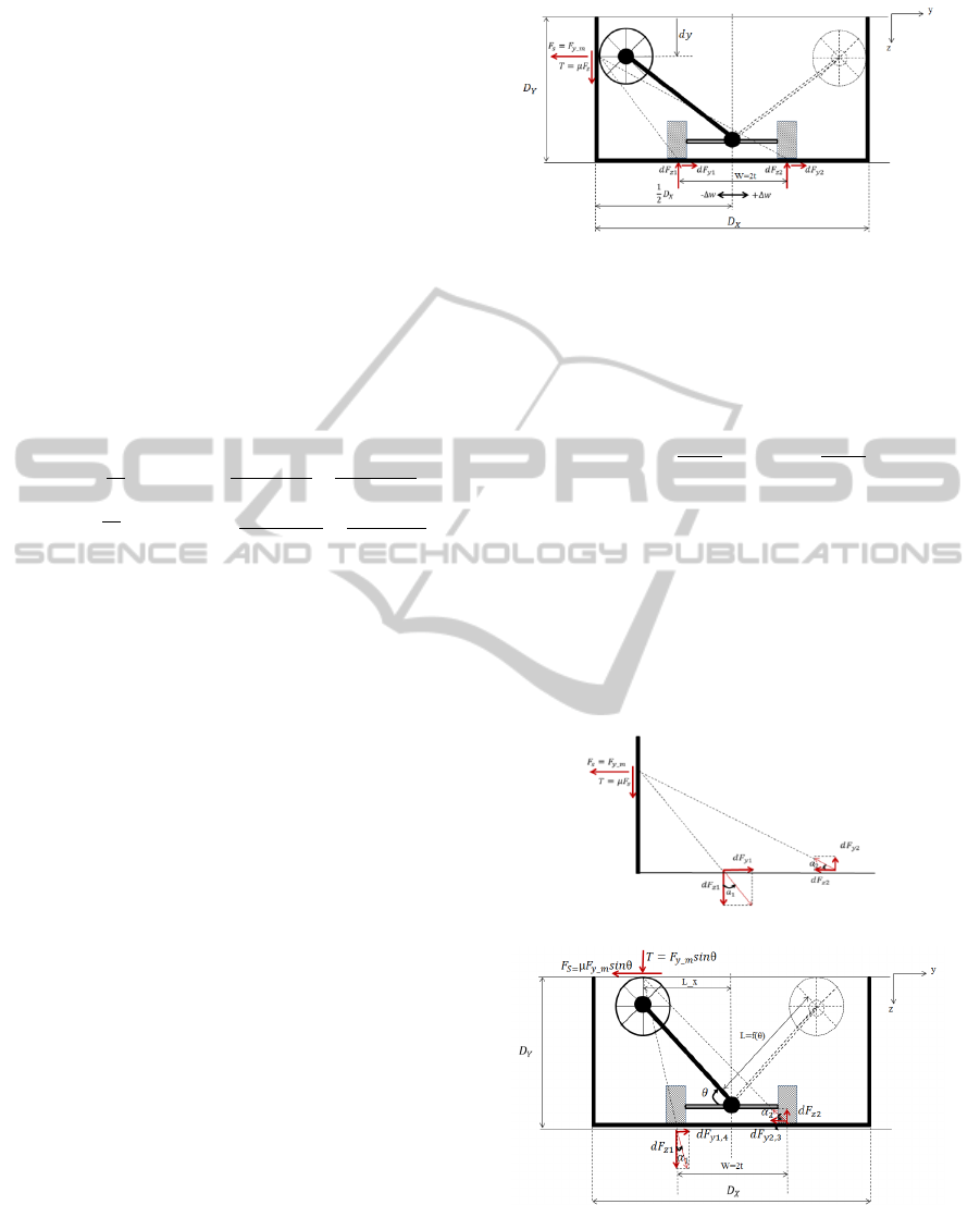
As depicted in Figure 2, the rubbing motion of the
rolling brush arm covers two side surfaces and upper
surface of the ventilation duct. When the brush
contacts with side surfaces (CASE I), the vertical
forces and geometric relationship under surface
friction are illustrated in Figure 2.
When the brush meets the surface of the duct,
reaction force (F
s
) and friction force (T) act as
resistance forces in cleaning process. Also, F
s
and T
enforce additional forces to the wheels of the mobile
Figure 2: A schematic of forces exerted on target surfaces
from brushing arm and mobile platform.
platform. The force equilibrium equation between
wheels and surface is given by
∑
0;
2
2
, (20)
∑
0;
_
2
2
, (21)
∑
0;2
2
0
(22)
In a case of upper surface cleaning motion, the
interaction forces between the wheel and the rolling
brush (CASE II) is illustrated in Figure 3. The
difference between CASE I and CASE II is the
direction of vertical forces on the cleaning surface
and platform wheels. Since the direction of
interacting forces in two cleaning positions of the
brushed arm, control forces have to be calculated by
considering different directions of each reacting
forces from surfaces.
(a) CASE I
(b) CASE II
Figure 3: Free body diagram of interacting forces between
the platform and target surfaces.
The vertical load and the lateral force divided by
ICINCO2014-11thInternationalConferenceonInformaticsinControl,AutomationandRobotics
558
wheels and the road interaction as shown in Figure 3
can be calculated as
CASEI:d
,d
,
d
,
(23)
CASEII:d
,
d
,
d
2
′
2
′
2
′
2
′
.
(24)
The angle
and
are given by
∆
,
∆
,
∆
,
∆
,
(25)
where ∆ is the position change of the mobile
platform, dy is the vertical change of the brush
position, and
,
is the dimension of the
rectangular duct. The tangential force generated by
pressurizing and scrubbing the duct surface
influences traction forces of the both wheels.
However, since responding force on each wheel is
different, motor torques for controlling each wheel
have to be calculated independently for increasing
control stability of the mobile platform. According
to the Equation (2), traction exerted to the wheel can
be decided by the magnitude of the load.
In braking, it is required to consider direction of
motor torque because there exist negative loads and
traction forces for each wheel. To resolve this
problem, it is also assumed that the lifting effect by
negative force on the wheel is zero traction force.
Considering the forces acting on wheels
overloaded by rolling brush during cleaning motion
of the arm, the reaction forces of c
q,
in Equation
(5) can be rewritten as
,
∅
∅
∅
∅
, (26)
, (27)
∑
, (28)
∆
∆
,
(29)
where
is the sum of extra longitudinal forces at wheels,
is the sum of extra lateral forces at wheels,
is the moment generated by additional forces.
2.3 Kinematic Analysis of the Rotating
Brush Arm
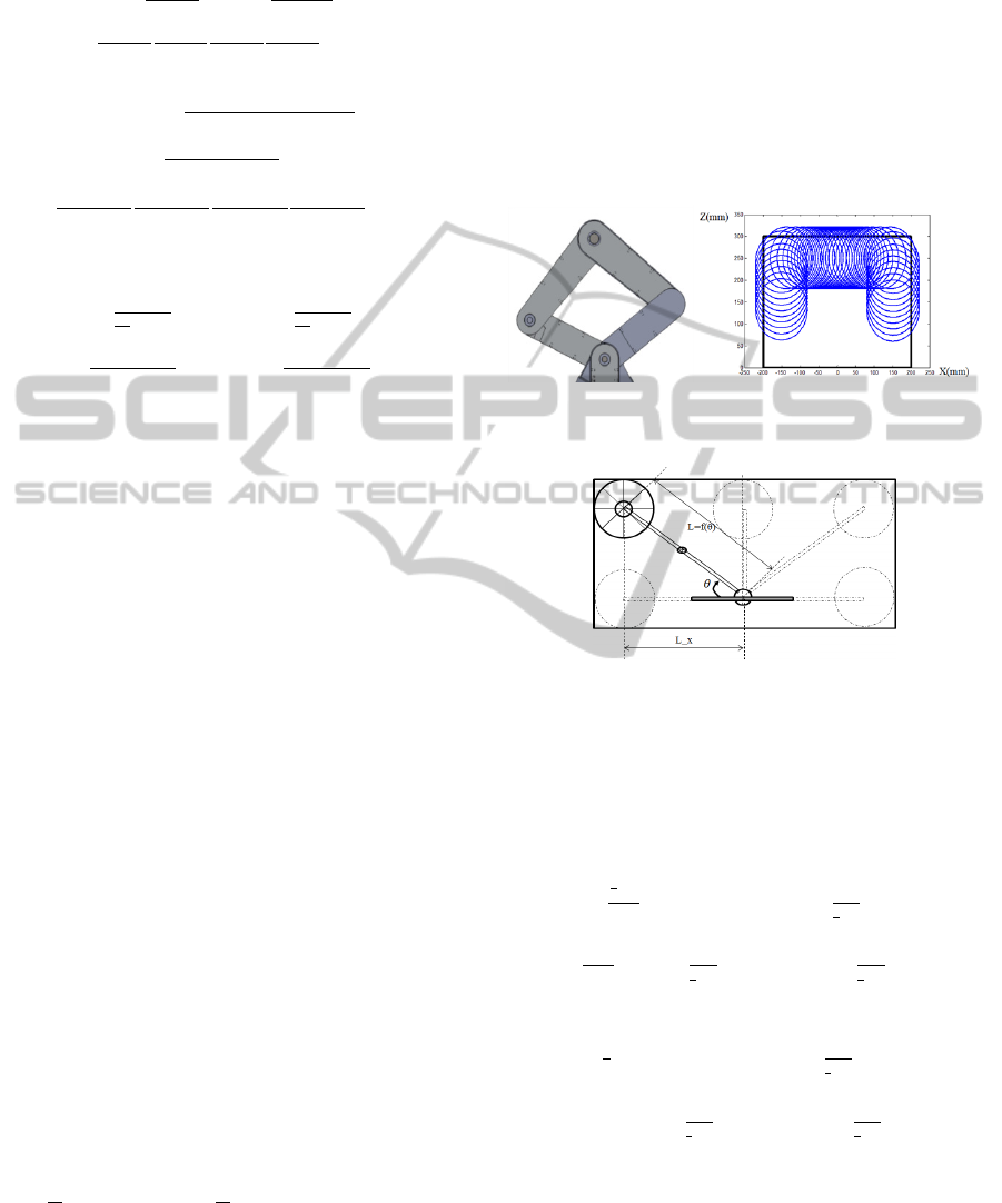
With a simple five link-mechanism, workspace of
the rolling brush can be analysed as shown in Figure
4. However, for the simplicity of mechanism and
control, the linkage can be modelled with a prismatic
link and a revolute joint as depicted in Figure 5.
Figure 4: Workspace of the 5 link manipulator with rolling
brush.
Figure 5: Simplified kinematic model of robotic arm.
As depicted in Figure 5, the length of the link
becomes a function of the rotation angle (theta)
whose workspace can be expressed by following
function. The pushing force acting by the link can be
modelled as illustrated in Figure 6.
L
θ
∶ 0
∶
,
L
1
2
∶0
∶
,
(30)
AStableTrackingControlofSkidSteeredMobilePlatform
559
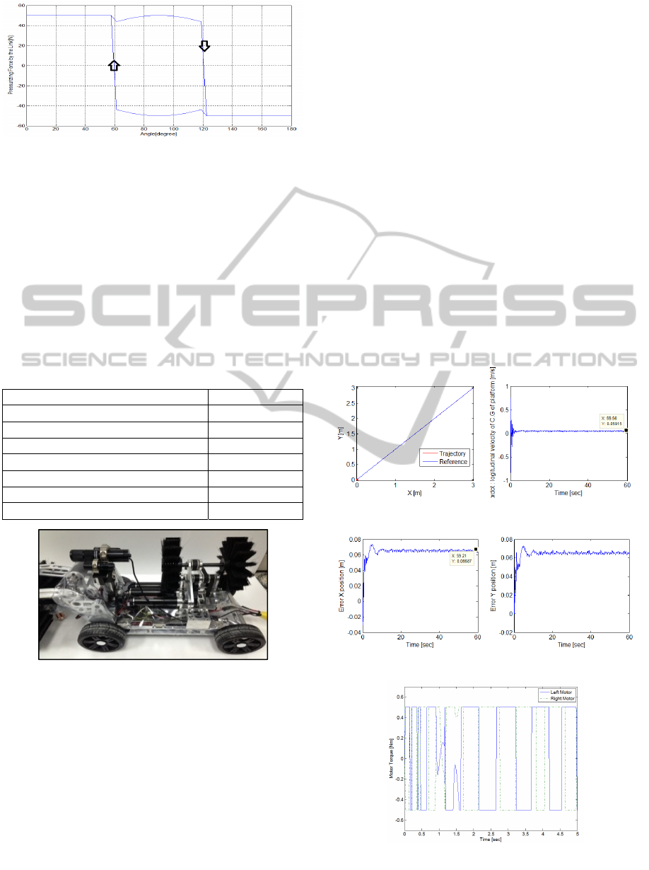
Figure 6: Duration of the load applied by using simplified
model of variable length of the link with rolling brush.
3 SIMULATION AND RESULTS
The control algorithm for stable trajectory tracking
presented in section 2 has been simulated with a
MATLAB
TM
tool. Based on the prototype of duct
cleaning robot as shown in Figure 7, mechanical
parameters in simulation are selected and
summarized in Table 1.
Table 1: Summary of the mobile platform model.
Length (L)
0.30 [m]
Distance from C.M to front axle(a) 0.15 [m]
Distance from C.M to rear axle (b) 0.15 [m]
Track Width (W) 0.23 [m]
Radius of wheel (r) 0.05 [m]
Overall mass of Duct cleaning robot 7.823[kg]
Inertia of the platform 0.19 [k
gm
2
]
Mass of the manipulator 1.777 [k
g
]
Figure 7: Prototype of the duct cleaning robot.
The desired trajectory is
0.05,
0.05
as a straight line whose angle in the view of absolute
coordinates is ∅=45[deg] for t∈0,60sec. The
speed of the mobile platform was set to 0.05m/s and
the period of the cyclic motion traveling arms to
clean both sides of the duct is 1 second. To prevent
singularity of the equation of motions, the initial
velocities and angular velocity of the platform
should not be zero (Yang et al, 1999). The friction
coefficients of duct surfaces are set to
0.895
and
0.1, respectively. The initial velocity
of wheels is 0.01m/s and the initial angular velocity
at CM is set to 0.02 rad/sec.
The load caused by the link with rolling brush is
set to 50[N] with iterative calculation to keep
stability of moving platform. The simple motor
model has used whose torque saturation limit is set
as 0.5 [Nm]. In order to track the reference path, the
parameters of Equation (19) are chosen as
4,
28,
75 to minimize tracking error (De
Luca, 1998).
Simulation results for trajectory tracking of the
mobile platform are shown in Figure 8. The position
errors of longitudinal and lateral direction were
controlled within 4mm shown in Figure 8(c) and (d).
It is also considered that lateral forces were exerted
at four wheels against the load by the link with
rolling brush to surface planes. The mobile platform
was controlled to sustain posture with two actuators
under the changing lateral loads on wheels.
Additional method in tracking against the lateral
load is required to reduce the magnitude of the
fluctuated error.
(a) Position X-Y [m] (b) vehicle speed[m/s]
(c) Position Error X[m] (d) Position Error Y[m]
(e) Motor Torque [Nm]
Figure 8: Simulation results for trajectory tracking.
ICINCO2014-11thInternationalConferenceonInformaticsinControl,AutomationandRobotics
560

4 CONCLUSIONS
A dynamic trajectory tracking controller in the
application of moving arm with rolling brush has
proposed for skid steered mobile platform.
Considering nonholonomic constraint with skidding
wheels, the controller consists of proportional terms
with kinematic elements (e.g. position, velocity,
acceleration) of the platform. A nonlinear
characteristics concerning about tire deformation has
been neglected by considering the lateral friction
coefficient as a constant. Simulation results indicate
that the mobile platform can be skid-controlled
under external force. However, when the external
force over 50N was enforced, the controller should
be modified to minimize the position error of the
platform.
ACKNOWLEDGEMENTS
This research was carried out as a part of project
(13RTRP-B069116-01) partially funded by the
Ministry of Land, Infrastructure and Transport and
Ministry of Science, ICT and Future Planning in
Korea.
REFERENCES
Kanayama, Y., Kimura, Y., Miyazaki, F., Noguchi, T.,
1991. A stable tracking control method for a
nonholonomic mobile robot. IEEE/RSJ Int. Workshop
Intelligent Robots and Systems, pp.1236-1241.
Samson, C., Ait-Abderrahim, K., 1991. Feedback control
of a nonholonomic wheeled cart in Cartesian space. in
Proc. IEEE Int. Conf. Robotics and Automation,
pp.1136-1141.
Sampei, M., Tamura, T., Itoh, T., Nakamichi, M., 1991.
Path tracking control of trailer-like mobile robot. in
Proc. IEEE/RSJ Int. Workshop Intelligent Robots and
Systems, pp. 193-198.
Fukao, T., Nakagawa, H., Adachi, N., 2000. Adaptive
Tracking Control of a Nonholonomic Mobile Robot.
IEEE Transactions on Robotics and Automation, Vol.
16(5), pp.609-615.
Shojaei, K.,Shahri, A. M., 2012. Output feedback tracking
control of uncertain non-holonomic wheeled mobile
robots: a dynamic surface control approach, IET
Control Theory and Applications, Vol6(2), pp. 216-
228.
Marvin, K. B., Simon G. F.,Liberatoi, C., 2009. Dual
Adaptive Dynamic Control of Mobile Robots Using
Neural Networks, IEEE Trans. on Systems, Man, and
Cybernetics, Vol.39(1), pp. 129-141.
Bekker, M. G., 1969. Introduction to Terrain-Vehicle
Systems, Ann Arbor, MI: University of Michigan Press.
Wong, J. Y., 2001. Theory of ground vehicles, John Wiley
and Son,3
rd
edition.
Caracciolo, L., 1999.Trajectory Tracking Control of a
Four-Wheel Differentially Driven Mobile Robot, IEEE
International Conference on Robotics and Automation,
pp.2632-2638.IEEE.
Yi, J.,Song, D.,Zhang, J., Goodwin, Z., 2007.Adaptive
Trajectory Tracking Control of Skid-Steered Mobile
Robots, IEEE Conference on Robotics and
Automations,pp.2605-2610. IEEE.
Anthony, M., Jorge, L. M.,Jesus, M., Jose, L.
B.,2007.experimental kinematics for wheeled skid-
steer mobile robots, Proc. IEEE/RSJ Int. Conference
of Intelligent Robots System, San Diego, pp.1222-1227.
Jeong, W.,Jeon, S., Park, D., Kwon, S.,2013.Surface
Cleaning Force Control of Rotating Brushes For an
Air Duct Cleaning Robot, International Conference on
Informatics in Control, Automation and
Robotics(ICINCO), pp. 453-457. SCITEPRESS.
De Luca, A., Oriolo, G., Samson, C., 1998, Feedback
control of a nonholonomic car-like robot, in J. P.
Laumond (Ed.) Robot Motion Planning and Control,
Lecture Notes in Control and Information Sciences,
Vol. 229, pp.171-253, Springer-Verlag, London.
Will, A. B., Zak, S. H., 1997. Modeling and control of an
automated vehicle, Vehicle System Dynamics, Vol. 27,
pp.131-155.SWETS AND ZEITLINGER.
Yang, J., Kim, J., 1999.Sliding Mode Control for
Trajectory Tracking of Nonholonomic Wheeled
Mobile Robots, IEEE Transactions on Robotics and
Automation, Vol. 15, No. 3, pp.578-587.
AStableTrackingControlofSkidSteeredMobilePlatform
561
