
Building a ROS Node for a NMEA Depth and Temperature Sensor
Robert Codd-Downey, Michael Jenkin and Andrew Speers
Department of Electrical Engineering and Computer Science, York University, Toronto, Canada
Keywords:
ROS, Sensors, Depth-sounder, Autonomous Surface Craft.
Abstract:
Although many commercially available robots ship with a version of ROS this is not as true for many external
sensors. There is a lack of ROS support for many devices and sensors one might use to extend the capabilities
of a robot. As robots are deployed in more complex environments there is the need for more specialized
sensors. In particular in the aquatic domain there is the need for support for depth sounders. This paper
describes the design and construction process for building a ROS node for a NMEA 0183 compliant depth and
temperature transducer and a strategy for extending this design to other NMEA devices.
1 INTRODUCTION
Although the vast majority of autonomous systems
are designed to operate on the ground (ground-contact
robots) there is considerable interest in the develop-
ment of devices that operate in the air, under the wa-
ter, and on its surface. As devices move off of solid
ground it becomes necessary to develop and deploy
sensor systems that can deal with these novel envi-
ronments. To make this task more concrete, consider
the problem associated with operating a device such
as the Clearpath Kingfisher robot shown in Figure-1.
This device is essentially an aquatic differential drive
vehicle powered by two propellors mounted in paral-
lel. Similar to traditional differential drive vehicles
operated on land, choosing different thrusts from the
two motors produces different motion trajectories on
the water’s surface.
As shipped, the Kingfisher comes equipped with
limited onboard computation, differential GPS and
wireless communication to an external operator. Con-
trol of the vehicle is provided through a ROS-based
(Quigley et al., 2009) software infrastructure. We
have augmented the stock vehicle in a number of
ways, including through the addition of additional on-
board computation and a range of different sensor sys-
tems including the system described here.
Although monitoring events occurring above the
surface is vital for an autonomous surface vehicle, it
is also critically important that such devices are able
to sense properties of the environment below the wa-
ter’s surface. Underwater obstructions and shallowing
of the water associated with the shoreline are impor-
tant features of the environment that must be moni-
tored. Of critical importance here is ensuring vehicle
safety. Striking an underwater obstruction or beach-
ing the robot can be disastrous. Although sensing for
such a task can be performed at least in part through
the use of vision and similar sensors mounted on the
vehicle, it is essential that the vehicle be aware of the
depth of the water column beneath it. Although vi-
sion and similar sensors can play some role in this,
vision may fail when the water turbidity prevents a
good view of underwater obstacles or if environmen-
tal conditions prevents the sensor from observing ob-
stacles that protrude from the water’s surface. An ob-
vious approach here is to augment the robot with one
or more depth sensors that measure the depth of the
water column directly. A depth sensor does not suf-
fer from many of the shortcomings associated with
surface sensors, and if properly designed can be eas-
ily integrated into the existing sensor suite mounted
on the vehicle. Depth sensors are routinely deployed
in the marine environment where standard packaging,
power and communication infrastructures have been
developed. Unfortunately the standards prevalent in
the marine environment are not directly compatible
with research robot infrastructure. This paper de-
scribes the process of adapting a commercial NMEA
0183-compliant depth sensor for autonomous vehicle
use. Specifically, we demonstrate how such a device
can be exposed to an autonomous system as a ROS
node.
The Robot Operating System (ROS) (Quigley
et al., 2009) has included support for National Ma-
rine Electronics Association (NMEA) 0183 (Associa-
506
Codd-Downey R., Jenkin M. and Speers A..
Building a ROS Node for a NMEA Depth and Temperature Sensor.
DOI: 10.5220/0005066305060512
In Proceedings of the 11th International Conference on Informatics in Control, Automation and Robotics (ICINCO-2014), pages 506-512
ISBN: 978-989-758-040-6
Copyright
c
2014 SCITEPRESS (Science and Technology Publications, Lda.)
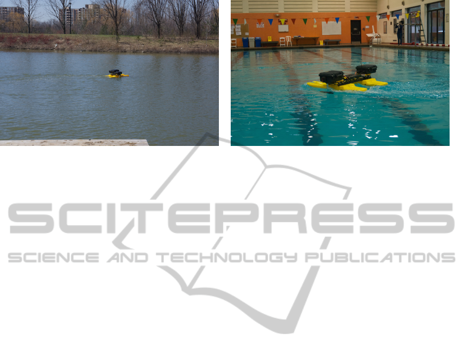
(a) Kingfisher operating on a pond. (b) Closeup of the Kingfisher.
Figure 1: The Kingfisher operating on a pond on the campus and in the campus pool. The device is essentially a differential
drive vehicle.
tion et al., 2003) compliant GPS devices for a number
of releases (Perko and Martin, 2012), however there
is a tremendous lack of support for the wide vari-
ety of other devices supported by the NMEA proto-
col. NMEA evolved as a standard to enable a wide
range of marine sensors and systems to be integrated
within a common framework and although this frame-
work includes GPS sensors, GPS is not the only ma-
rine technology sensor that can be repurposed for au-
tonomous systems. Many marine vessels are outfitted
with electronic depth sensors. Apart from basic nav-
igation tasks, depth sensors are deployed to address
many different marine applications. For example,
bathymetric maps are an integral part of safe marine
navigation in that they help mariners avoid underwa-
ter hazards. The OpenSeaMap (OpenSeaMap, 2009)
project is a crowdsourcing effort to create a world-
wide bathymetric chart, contributions can be made by
anyone with a depth sounder and GPS. Apart from
navigation these maps are useful in a variety of appli-
cations from exploration and planning to the study of
underwater volcanoes and earthquakes.
2 BACKGROUND
2.1 Echo Sounders
Echo sounders are sonar devices that are used to de-
termine the depth of water using pulses of sound. A
transducer mounted either through the hull or in the
bottom of the boat is used to transmit sound pulses
into the water column. The transducer also listens
for the return pulse. Pulses are produced within the
echo sounder using a piezoelectric transducer that
contracts when a voltage is applied. This rapid expan-
sion and contraction creates a pressure wave that trav-
els through the water and echoes back after bouncing
off the bottom. Upon return, this wave is converted
back to an electrical voltage and the travel time is then
used to calculate the depth below the transducer. One
critical issue here is that the speed of sound in water
varies with temperature and thus most depth sounders
also monitor water temperature in order to correct for
this variation. A second issue is that although the echo
pulse may have substantive power in side lobes, to a
first order approximation the echo sounder beam can
be though of as travelling in a straight line down from
the transducer. It is thus critical to know the direc-
tion in which the transducer is pointing. This issues
becomes particularly acute in the presence of wave
action that induces roll and pitch on the vessel.
2.2 NMEA 0183 and NMEA 2000
Although many different communication and control
strategies exist for commercial echo sounders two
standard protocols have emerged. NMEA 0183 is
a simple ASCII communications protocol operating
over a 4.8 kbps serial data bus, developed by the Na-
tional Marine Electronics Association. Unlike serial
communications, associated with computers that sup-
port the RS232 standard, NMEA 0183 devices utilize
the RS422 standard. The RS422 standard differs from
RS232 in two fundamental ways: first, the RS422 is
a differential protocol and second, the NMEA 0183
does not rely on a 5V reference signal. Many NMEA
devices operate at a much higher voltage level than
that associated with modern electronics requiring care
when connecting them to standard computer hard-
ware. Notwithstanding the electrical differences, the
NMEA 0183 protocol is a serial protocol in which
talkers – devices that generate sentences – provide
BuildingaROSNodeforaNMEADepthandTemperatureSensor
507
data that is transmitted from a single talker to multiple
listeners in parallel. The newer NMEA 2000 proto-
col is slowly being adopted in favour of its predeces-
sor, the NMEA 0183. The NMEA 2000 (Association
et al., 2005) is a network protocol built on top of the
controller area network bus supporting both multiple
talkers and multiple listeners at 250 kbps. Another
difference between the NMEA 0183 and NMEA 2000
protocols is a switch from ASCII encoded data sen-
tences to a compact binary format with a proprietary
specification (Spitzer et al., 2009).
2.3 From Echo Sounders to ROS
A wide range of devices support the NMEA 0183 pro-
tocol. In terms of the robotics community, perhaps
the most well integrated of these devices are GPS re-
ceivers. Fortunately, a number of researchers have
developed software infrastructures that support GPS
devices and this investment is easily repurposed for
Echo Sounders that support the NMEA 0183 proto-
col.
ROS has become a de-facto standard for much
of the autonomous robot community and its use
is especially prevalent in the research community.
Within ROS, processes are represented as nodes
which communicate through messages within a pub-
lisher/subscriber framework. The process of integrat-
ing echo sounders within a ROS infrastructure in-
volves providing the necessary power/data connec-
tions to the device and then transducing messages re-
ceived from the echo sounder into corresponding ROS
messages.
3 PHYSICAL CONSTRUCTION
A critical aspect in the construction of any component
of a field robot, and this is especially true for robots
working near water, is ensuring that the device is iso-
lated from its environment. Incidents that are only a
minor annoyance for a robot operating indoors can be
catastrophic for a field robot. For the echo sounder
system described here, water is of particular concern.
Although exposure to fresh water might be brushed
aside, salt-water or water from chlorine-treated pools
can result in permanent damage to electric circuits,
and there is always the possibly of complete emersion
due to wave and sea action. In order to deal with this
issue, we have encased the sensor in a water-proof
housing. Two different sensor housings have been
built. The first, an experimental housing, is shown
in Figure-2(a) while the production housing is shown
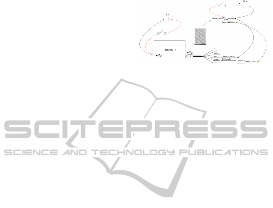
Figure 3: RECHOS wiring diagram.
in Figure-2(b). In both cases the devices are designed
to be sealed against the elements.
In the design of any device that will be deployed in
harsh environments breaks in the case should be min-
imized. Switches mounted externally to the case are
designed to be waterproof, and the number of cables
leaving the device are minimized. The experimental
housing was designed to be completely sealed, with
communications to and from the device being accom-
plished via a wireless signal. For the production de-
vice we have augmented the wireless capability with
the ability to hardwire the device into the ROS net-
work should this prove desirable.
The experimental housing is based on a cylindri-
cal underwater enclosure. Acrylic ports are used to
seal the caps of the cylinder. Three toggle switches
are mounted to the top port. Two are used to con-
trol power to the transducer and onboard electron-
ics. The third is available for use by application soft-
ware. This configuration allows for pre- and post-
deployment testing, and testing of the system out of
water using a mobile device or laptop, with the trans-
ducer safely powered off. The production housing is
based around standard ABS pipe infrastructure and
is designed to be more easily mounted on the King-
fisher and other robot platforms. This improved hous-
ing also includes additional ports facilitating ethernet
connectivity and the recharging of batteries.
The sensor packages are designed to be a self-
contained systems so as to enable the device to
be fully portable. Although the planned deploy-
ment of the production device involves the Kingfisher
robot (Figure-1) it is intended that the device will
also be deployed on other devices including recre-
ational/commercial vessels. In such deployments it
may not be straightforward to provide physical wiring
between the sensor and power/data networks.
The ROS echo sounder (RECHOS) is comprised
of three major components. The production version
includes an additional component to improve the
accuracy of sensor readings.
ICINCO2014-11thInternationalConferenceonInformaticsinControl,AutomationandRobotics
508
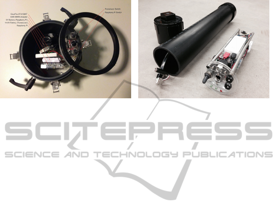
(a) Experimental housing. (b) Production housing.
Figure 2: RECHOS sensor housing. (a) shows the experimental housing used for field tests to validate the design. (b) shows
the production housing designed to be mounted on the Kingfisher platform shown in Figure-1.
• An Echo Sounder. The CruzPro-
ATU120AT(CruzPro, 1997) is an active depth
and temperature transducer requiring 9.5-16.0
VDC at 350 mA that transmits data at 1Hz using
the NMEA 0183 communications protocol.
• Signal Transducer Computer. The RECHOS
uses a Raspberry Pi Model-B Rev-01 for signal
processing. This computer is small single-board
computer requiring 5VDC at 700 mA.
• RS422 to USB Converter. A USB-NMEA
0183 adapter provides bi-directional communica-
tion with NMEA compliant devices over a virtual
COM port and is used to connect the transducer to
the computer.
• ADXL345 Accelerometer (Production Hous-
ing). A triple-axis accelerometer with digital I2C
interface provides tilt information which is used
to correct depth readings.
Beyond these major components the RECHOS must
also deal with the realities of providing power to the
various devices and allowing an operator to start and
stop the device. The power requirements of the trans-
ducer are unusually high in comparison to the require-
ments of mobile computing devices like the Rasp-
berry Pi. The transducer was originally developed to
be operated off of standard boat power (unregulated
12V) rather than off of the well conditioned power
associated with modern computer electronics. This
disparity identifies a need to separate and isolate the
power supplied to the two devices (Figure-3).
One unfortunate property of the echo sounder
used in this project – and this is quite a common prop-
erty of many such devices – is that they should not be
operated out of water. In order to enable software de-
velopment on the RECHOS a separate power discon-
nect was provided for the power supply to the echo
sounder.
4 SOFTWARE
A Raspberry Pi provides essential on-sensor compu-
tation. It transduces messages from the echo sounder
and presents them as ROS messages to the ROS sys-
tem using standard network infrastructure. Messages
from the echo sounder appear as serial messages
through the USB port on the Raspberry Pi. A ROS
node running on the Raspberry Pi parses raw NMEA
0183 sentences from the depth and temperature trans-
ducer using the PySerial library (Liechti, 2001) and
subsequently publishes this information along with
the raw data for further consumption by the system.
Additional information about the powered state of the
transducer is inferred by the ROS node and published
as a latched topic so as to inform all new subscribers
about the current state of the device. This is pos-
sible because the transducer always outputs NMEA
sentences at a rate of 1 Hz while powered on, regard-
less as to whether it has any depth information to re-
port. Should no messages be received from the echo
sounder within 1.5 seconds the device is assumed to
have been powered off.
Custom ROS messages corresponding to the
depth, temperature, device state, and raw data are de-
fined for the various messages published by the RE-
CHOS device. A custom ROS service is bundled
within the node to facilitate the creation of rosbag
files for the purposes of data collection. The service
only handles one recording request at a time, how-
ever this is an acceptable limitation. Further recording
can be accomplished using the rosbag command line
BuildingaROSNodeforaNMEADepthandTemperatureSensor
509
tool bundled with ROS. The Raspberry Pi is equipped
with both wired and wireless Ethernet providing sub-
stantive communications connectivity to the ROS net-
work.
The ROS service defines two requests and four re-
sponses (generated based on the success of actions
taken to fulfill the request and correspond to the cur-
rent state of the recorder service):
Requests
• start - request to start recording data to a new ros-
bag file
• stop - request to stop the current recording
Responses
• recording started - response to a successful start
request
• already recording - response to a start request
when there is already an active recording
• recording stopped - response to a successful stop
request
• nothing to stop - response to a stop request when
there are no active recordings
This general topic structure can be reused for
other types of NMEA 0183 sensors utilizing one-way
communication. The general topics (Raw, State and
Recorder) carry functionality useful for many sen-
sors. Providing RAW data from the device eases the
debugging of sensor malfunctions by facilitating the
verification of message integrity and checksum data.
The recorder service simplifies the process by which
rosbag files can be created in a wireless environment
where connectivity to the device cannot be maintained
or guaranteed. Without this service it can be difficult
to properly shut down the recording of rosbag files
which can result in a loss of data. If the state of the de-
vice can be accurately inferred such information can
be used to stop and start other processes that make use
of its data. The data topics (Depth and Temperature)
are specific to the type of sensor and others would be
required for other classes of NMEA sensors.
4.1 Correcting Depth Readings
A major limitation with the development version of
the sensor was due to the lack of inertial data. Ac-
curate depth readings could not be maintain with
changes in tilt due to wave action and other forces act-
ing on the surface vessel. For this reason a triple-axis
accelerometer was included in the production version
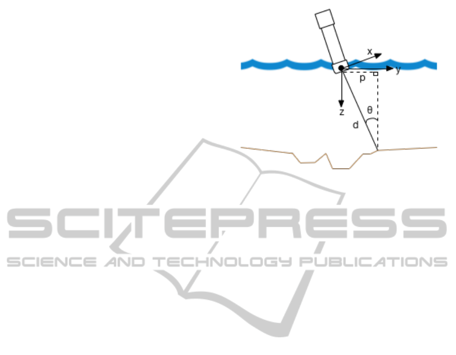
of the sensor. Figure-4 shows the geometry of the
situation. Let the sensor be mounted at the origin
Figure 4: Sensor geometry displaying depth error due to tilt.
aligned with the z axis (pointing down) and the x-y
plane lying in the nominal surface of the water. Wave
action will cause the boat to roll and pitch relative to
the nominal surface and thus the recovered depth d
will not be recorded along the z axis, but rather will
recorded along the vector
ˆ
d. If we encode the recov-
ered depth d as a vector
~
d = d
ˆ
d, then the true depth
is ˆz ·
~
d, and under the assumption that there are no ob-
structions between the surface and the bottom then the
corresponding surface position p for this depth mea-
surement is given by ( ˆx ·
~
d, ˆy ·
~
d).
5 TESTING
Ensuring that equipment is functioning properly and
producing meaningful data is an important part of any
testing procedure in the field. Wasting valuable time
in the field collecting unusable data or not collecting
any data is unacceptable. Due to the limited amount
of feedback available from visual checks of the RE-
CHOS apart from a number of status lights – of which
only three are of importance (Raspberry Pi power,
wifi dongle connection, data transmission from the
sensors) – other forms of feedback are necessary to
confirm proper functionality. A mobile device can
connect to the onboard computer and view console
messages and data from the sensor, however parsing
these messages for desired information is difficult due
to the speed at which they are generated. A more visu-
ally pleasing and informative view of the sensor read-
ings is required. In keeping with this requirement an
android application was created to wirelessly monitor
sensor readings from the system and display them to
the user. The application utilizes the android library
described in (Speers et al., 2013). The application in-
terfaces with the RosBridge (Crick et al., 2011) suite
ICINCO2014-11thInternationalConferenceonInformaticsinControl,AutomationandRobotics
510
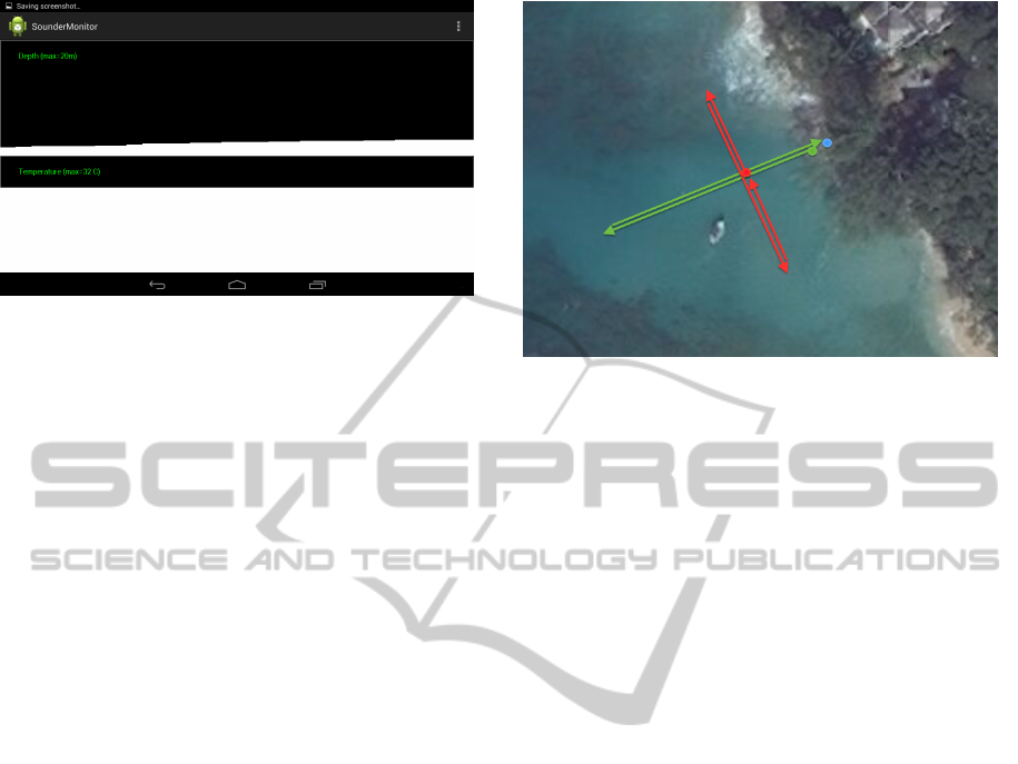
Figure 5: Android Monitor Application.
running on the RECHOS and subscribes to the neces-
sary topics to receive messages for depth and temper-
ature. Figure-5 shows a screenshot from the android
application which draws the latest depth and tempera-
ture values on two graphs for easy visualization when
in wireless communication range of the system.
5.1 Bucket Tests
Testing the sensor on a lab bench risks damaging the
piezoceramic transducer in the echo sounder. The
rapid expansion and contraction of the piezoceramic
material generates considerable heat and without the
thermal conductive properties of the water this heat
can damage the device. In order to accommodate this
requirement initial tests of the transducer were con-
ducted in a lab setting using a large bucket filled with
water. These tests were done to acquire knowledge
about the transducer which was not included in the
specifications provided by the manufacturer. For ex-
ample, the transducer will continue to function at low
voltages, e.g. 4.5 - 9.5 VDC, however depth read-
ings become erroneous and reported temperatures be-
gin to climb well above manufacturer specification for
the device (0
◦
C - 32
◦
C). As well in some cases the
transducer can take up to ten seconds before produc-
ing depth readings.
5.2 Field Tests
The sensor was tested during the NCFRN (NSERC
Canadian Field Robotics Network) field trails at
McGill’s Bellairs Research Institute in Holetown,
Barbados. A bobbing test was first conducted in shal-
low water in order to determine the expected variabil-
ity in depth due to fluctuations in wave height. Fol-
lowing this test two depth profiles were collected, one
parallel and one perpendicular to the shore. The map
in Figure-6 provides an overview of the testing site
and the routes taken which have been colour coded to
the test data shown in Figure-7.
Figure 6: Overview of the testing area for the development
housing.
The tracks for both of the perpendicular and par-
allel shore depth tests were completed both forward
and backwards so that reproduction of the depth in-
formation could be verified. The perpendicular shore
depth test was conducted along a route that lacked
underwater coral features so that only the depth pro-
file away from shore could be obtained. The paral-
lel shore depth test was conducted along a route with
coral features at either end. The device has also been
tested under less desirable environmental conditions.
Figure-8 shows the production version of the device
being tested in Lake Seneca near Toronto, Canada.
Testing here validated the basic construction of the
production device. It also identified an issue with bat-
tery discharge rates under extreme cold conditions.
Based on these results the battery used in the produc-
tion device has been modified to have a higher capac-
ity than was needed for the tests in Barbados.
6 RESULTS
Figure-7a shows the results from the bobbing test.
The sensor was held stationary while it bobbed up
and down in the water column, this is far from a com-
prehensive test case for the study of changing water
depths, it does provide a good indication of expected
variability of depths recorded by the sensor. The stan-
dard deviation of the resulting data is 0.1m, represen-
tative of the wave action present during testing.
Since the RECHOS was handled by a swimmer
traversing each route there were two factors that in-
fluenced the repeatability of the sensor motion data.
First, the degree to which sensor velocity could be
maintained. Changing velocity of the swimmer could
compress or stretch the depth profile. Second, de-
viations of the swimmer from the original path po-
BuildingaROSNodeforaNMEADepthandTemperatureSensor
511
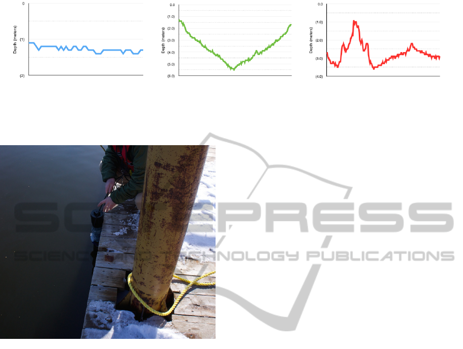
(a) Bobbing Test. (b) Perpendicular Shore Depth. (c) Parallel Shore Depth.
Figure 7: Experimental results obtained from the RECHOS sensor during field trails at McGill’s Bellairs Research Institute
in Holetown, Barbados. Graphs are colour coded to routes overlaid on the map in Figure-6.
Figure 8: Testing of the production housing of the sensor.
tentially produce dramatically different results over
coral. However, results from both shore depth tests
shown in Figures-7b and 7c indicate that sensor data
produces similar results when passed repeatedly over
the same portion of the seabed.
7 CONCLUSIONS
Depth sensors are a critical sensor for autonomous
surface vessels. Commercial echo sounders utilize
power and communication protocols that are not con-
sistent with standard robotics power and communica-
tion protocols. This paper describes how appropriate
electronics and software can be used to convert these
NMEA 0183 devices to a standard ROS infrastruc-
ture. The approach described here is generalizable
and easily adapted to other classes of NMEA 0183
compliant sensors.
ACKNOWLEDGEMENTS
This work was supported by the Natural Sciences and
Engineering Research Council (NSERC) through the
NSERC Canadian Field Robotics Network (NCFRN).
REFERENCES
Association, N. M. E. et al. (2003). NMEA 0183 stan-
dard. National Marine Electronic Association Pub-
lications/Standards.
Association, N. M. E. et al. (2005). ”NMEA” 2000.
Crick, C., Jay, G., Osentoski, S., Pitzer, B., and Jenkins,
O. C. (2011). Rosbridge: Ros for non-ros users. In
Proceedings of the 15th International Symposium on
Robotics Research.
CruzPro (1997). CruzPro ATU120AT.
http://www.cruzpro.co.nz/active.html.
Liechti, C. (2001). PySerial. http://pyserial.sourceforge.net.
OpenSeaMap (2009). OpenSeaMap project.
http://www.openseamap.org.
Perko, E. and Martin, S. (2012). NMEA navsat driver.
Quigley, M., Conley, K., Gerkey, B., Faust, J., Foote, T.,
Leibs, J., Wheeler, R., and Ng, A. Y. (2009). ROS: an
open-source robot operating system. ICRA workshop
on open source software, 3(3.2).
Speers, A., Forooshani, P., Dicke, M., and Jenkin, M.
(2013). A lightweight tablet interface for command
and control of ros enabled robots. In Proc. Int. Conf.
on Advanced Robotics.
Spitzer, S., Luft, L. A., and Morchhauser, D. (2009).
NMEA 2000, past, present and future. In RTCM An-
nual Assembly Meeting and Conference.
ICINCO2014-11thInternationalConferenceonInformaticsinControl,AutomationandRobotics
512
