Process Characterization and Evaluation of NC Machining Processes
based on Macroscopic Engagement Simulation
Meysam Minoufekr, Pascal Schug and Mihir Joshi
CAx-Technologies, Fraunhofer-Insitute for Production Technology, Steinbachstr. 17, 52074 Aachen, Germany
Keywords: Numerical Control Machining Simulation, NC Machining Process Evaluation, Material Removal
Simulation.
Abstract: With a view to achieve stable production, nowadays the process design and planning goes through a time
and resource intensive correction loop. The process output after machining trials is used to determine the
critical process sections, and hence the experience of the process designer is decisive in the productivity of
the optimization loop and the process. The implementation of a machining simulation can enhance the
productivity of the process design and planning phase. The macroscopic engagement simulation provides an
efficient tool for process evaluation. Moreover, it provides a basis for derivation of microscopic geometric
process parameters, which have a direct correlation to mechanical and thermal loads. Thus, detailed
information relating to the cutting loads on the tool is derivable at every point on the toolpath, enabling
analysis of NC machining process based purely on the macroscopic geometric engagement between the
cutting tool and workpiece. This information regarding the engagement conditions can be used to
proactively identify potential critical process sections in a virtual environment thereby increasing the
process reliability. Thus a process design for an optimal tool load is possible resulting in improved tool life,
process efficiency and reduction in utilised resources.
1 INTRODUCTION
Milling technology is the most commonly used
material removal method in the manufacturing of
high value components, such as the turbine blades,
bladed discs (blisks), press tools (moulds and dies)
etc. These components are characterized by a
complex geometry of sculpted or free formed
surfaces (Choi et al., 1998). Moreover, aerospace
components are manufactured from Titanium and
Nickel based alloys which have high strength and
temperature resistance but poor machinability which
is a challenge in manufacturing. (Klocke, 2011).
Due to the complex geometry of the parts needed in
the mentioned industry sectors, there is a complex
kinematic of the machining processes. This leads to
variable contact conditions and variable load
between workpiece and cutting tool, followed by
acceleration of tool wear.
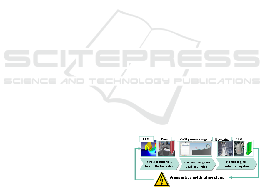
The state of the art CAx process chain is
depicted in Figure 1, where CAx stands for
computer based technology. The process design is
performed on the basis of information derived
from the simulation tests, and study of fundamental
Figure 1: CAx process chain.(Minoufekr et al., 2013).
process kinematics i.e. orthogonal cutting conditions
(Minoufekr et al., 2013, Zabel, 2010). A process
design based on the fundamental studies leads to
selection of conservative process parameters,
resulting in reduction of productivity. Moreover, the
critical sections in the process are first captured
during the stage of the NC machining the actual part
geometry. Thus, for a stable production with an
optimal process, an optimization loop of the NC
machining is necessary (Schug, 2012). If this
process is carried out in a simulation environment
and verified virtually, improvement in productivity
and reduction in costs can be achieved (Zabel,
2010).
661
Minoufekr M., Schug P. and Joshi M..
Process Characterization and Evaluation of NC Machining Processes based on Macroscopic Engagement Simulation.
DOI: 10.5220/0005054606610670
In Proceedings of the 11th International Conference on Informatics in Control, Automation and Robotics (ICINCO-2014), pages 661-670
ISBN: 978-989-758-040-6
Copyright
c
2014 SCITEPRESS (Science and Technology Publications, Lda.)
The process analysis in a simulation environment
enables the process designer to understand the
critical section in the process. With this information
pertaining to the process technology, an optimal
process design is possible. Thus this paper presents
an approach to create the technological basis
necessary for the analysis of multi-axis NC milling
processes. Section 2 provides a brief overview of the
existing machining simulation systems, and the
macro-simulation results are described. In Section 3,
directly derivable process characteristics are
assessed based on macro simulation. Furthermore,
the macroscopic simulation results are extended to
derive extra process knowledge regarding the
machining conditions. This is necessary for process
characterization and the subsequent evaluation of
NC machining processes. The paper is concluded in
Section 4.
2 TECHNOLOGICAL
BACKGROUND
AND PROBLEM DEFINITION
With the increase in the importance of the multi-axis
milling processes in the industry, the deployment of
computer based technologies (CAx technologies) is
imperative. The computer based technologies are
involved in the planning and verification of the
entire milling process in advance (refer Figure 1).
For this purpose, a virtual simulation of the NC
machining processes can provide an insight about
the real process conditions. Nonetheless, in the
existing simulation systems neither the process
behavior nor the phenomena occurring during the
process are considered.
2.1 State of the Art in Machining
Simulation
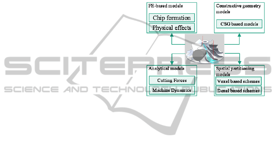
The last decades have seen a number of simulation
approaches being developed specifically for
determination of machining process parameters. The
most common approaches are the finite element
(FEM) based, analytical model based, and
geometrical model based (refer Figure 2).
Constructive Solid Geometry (CSG) based models
and the spatial partitioning models are the most
frequently deployed geometrical models for the
evaluation of the entire NC processes (Zabel, 2010).
The FEM based models are computationally
intensive and possess limited predictive capabilities,
thus their implementation in the milling process
planning is not practical due to the amount of time to
be invested for the calculation efforts. The analytical
model for cutter workpiece engagement cannot be
implemented for freeform surfaces since analytical
model equations are only valid for simplified
workpiece geometry. The geometry based models
focus mainly on the visual aspects of the resulting
geometry deriving very limited access to
technological process quantities.
Figure 2: Overview of existing simulation models for
machining processes. (Minoufekr et al., 2013).
The available milling simulation approaches based
on the dexel and voxel models focus less on the
physical properties. For e.g. Vericut provides
options for collision detection for three and five axis
milling processes (CGTech 2013). The obtained
results in the geometry based models are insufficient
since the modelling approaches are highly
simplified. Minoufekr et al. present a novel
alternative in (ICINCO, 2013), wherein the
macroscopic contact conditions are calculated for
every point on the cutting tool axis for every
toolpath point in the multi-axis milling. The
approach is referred to as macro simulation.
However, the model needs to be extended so that the
engagement on individual cutting edges can be
analysed.
2.2 Modelling of Macroscopic
Engagement Conditions
In the macro simulation, a slice model for a cutting
tool is used along with a multi-dexel model for the
workpiece in order to calculate the engagement
conditions along the tool axis at discrete points on
the toolpath. This modelling approach enables an
efficient calculation method for large toolpaths for
multi-axis machining of free-form surfaces. The
contact angle ϕ
c
is determined using the following
ICINCO2014-11thInternationalConferenceonInformaticsinControl,AutomationandRobotics
662
equation:
ϕ
c
= ϕ
ex
– ϕ
st
(1)
where, ϕ
st
and ϕ
ex
are the entry angle and the exit
angle respectively, as illustrated in Figure 3. The
axial depth of cut is denoted by a
p
, the cutting tool
radius by r
t
and the direction of the cutting velocity
and tool rotation by v
c
. Since the calculation of ϕ
st
and ϕ
ex
is independent of the cutting edges of the
cutting tool, these quantities are considered to be
macroscopic (Meinecke, 2009).
Figure 3: Macroscopic engagement conditions calculated
in macro-simulation (Meinecke, 2009).
In multi-axis machining, the tool orientation with
respect to the workpiece and the feed direction is
constantly changing along the NC toolpath. Due to
changing engagement conditions, the contact angle
is also varying along the tool axis and along the NC
tool path. This information can prove pivotal in
process evaluation. In order to calculate and use this
information, the cutting tool is discretized in slices
along its axis. Every tool slice is represented by k ϵ
[0, n], n being the total number of tool slices. For
axial slices, height for each tool slice is Δa
p
. The
contact angle for every tool slice is calculated
considering the surface envelope of the cutting tool
geometry using equation (2):
ϕ
c
(k)= ϕ
ex
(k) – ϕ
st
(k) (2)
Additionally the contact arc length (l
arc
) can also be
calculated according to equation (3):
l
arc
(k)= ϕ
c
(k) × r
T
(k) (3)
where, r
T
(k) is the radius of the tool slice. On the one
hand, the macro simulation delivers an efficient
approach for fast calculation of the tool workpiece
engagement in multi-axis milling on a high level of
abstraction. On the other hand, the macro simulation
cannot provide information relating to the individual
cutting edges in contact.
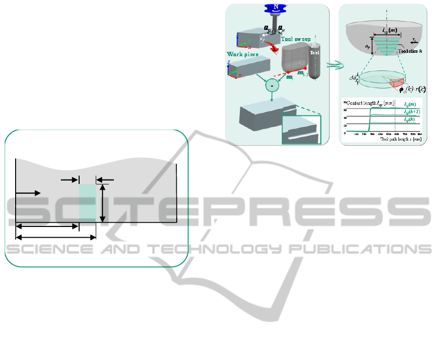
Figure 4: Geometric approach for macroscopic
engagement simulation of multi-axis processes.
(Minoufekr et al., 2013).
Due to this fact, direct derivation of the process
conditions is limited in the macro simulation. To
achieve a deeper understanding and to further derive
process characteristics, the goal of the current
research topic is to extend the macro simulation to
obtain detailed information regarding the individual
cutting edges.
2.3 Problem Definition and Research
Question
Multi-axis milling processes are characterized by the
dynamic nature of cutting tool workpiece
engagement. Thus mechanical and thermal load on
the cutting tool are also changing at different points
along the toolpath. Identification of engagement
conditions on the toolpath where unpredictable
mechanical or thermal load leading to tool wear, in a
simulation environment enables to proactively
eliminate the critical process phenomenon and thus
optimize the machining process. Literature review
suggests that mechanical load and thermal load are
proportional to geometrical input variables such as
axial depth of cut (a
p
), radial depth of cut (a
e
)
(Klocke, 2011) and contact length of cutting edge
(Bouzakis, 2008) respectively. Minoufekr et al.
established a link between the physical process
quantities for e.g. Force (F
c
) and the simulated
geometrical process quantities for e.g. the contact
angle (ϕ
c
) by macroscopic contact conditions
(Minoufekr et al., 2013). The macro simulation
provides a fast model to characterize the NC
machining processes on a higher abstraction level.
Due to this higher level of abstraction, the
capabilities of the macro simulation are limited with
regards to direct calculation of process conditions. In
the macro simulation, the engagement conditions
Macroscopic simulation
ϕ
st
.r
t
ϕ
ex
.r
t
v
c
ϕ
c
.r
t
a
p
ProcessCharacterizationandEvaluationofNCMachiningProcessesbasedonMacroscopicEngagementSimulation
663
regarding the individual cutting edges cannot be
directly calculated which is essential for a deeper
analysis of physical effects on the tool since the
engagement conditions on each cutting edge have a
direct link to cutting forces. Thus an extension of the
existing macro simulation is essential which presents
the research question of this work:
How can the macro simulation be extended so
that the contact per cutting edge can be determined
to characterize and evaluate the multi-axis milling
process?
3 SOLUTION AND METHOD
Macroscopic process characteristics such as the
cutting method can be determined using the macro
simulation result. With the mapping of cutting edge
geometry in the macro simulation, engagement
analysis of individual cutting edges is possible.
From the engagement analysis, the geometrical
parameters for process characterization are
determined. This enables characterization of the NC
machining process based on purely geometric
quantities. Then further the process is evaluated
based on the instantaneous values of the
characterization parameters. This approach is
illustrated in Figure 5.
Figure 5: Proposed approach for process analysis with
macro simulation.
3.1 Directly Derivable Process
Characteristics based on
Macroscopic Engagement
An important parameter during process design is the
selection of the cutting method, i.e. up-milling and
down-milling. C. Gey found that the tool wear in
down-milling is lower as compared to up-milling
(Gey, 2002), also during machining of aerospace
alloys for e.g. titanium alloys and nickel based
alloys, there is formation of chip root in up milling
and hence should be avoided (Klocke, 2011). Thus
identification of the cutting method provides
important insight about the engagement situation.
The cutting method can be directly interpreted from
the result of the macro simulation as illustrated in
Figure 6.
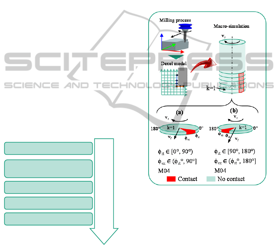
Figure 6: Definition of up-milling and down-milling in
macro-simulation for counter-clockwise rotation.
The direction vectors of cutting velocity v
c
and the
feed velocity v
f
are in opposite direction to each
other in the engagement region in up-milling, and
the direction vectors are parallel to each other in the
engagement region in down-milling (Klocke, 2011).
In the macro simulation, the values of the entry
angle ϕ
st
and the exit angle ϕ
ex
are plotted on the
surface envelope of the cutting tool model on each
tool slice. The position for 0° and 180° is illustrated
in Figure 6 and indicates the direction of
measurement of angles. The tool slice is divided into
four quadrants. The maximum possible contact angle
ϕ
c
is 180°. Hence the value of ϕ
ex
cannot exceed
180° and the minimum value of ϕ
st
is 0°.
NC Process analysis with macro
simulation
Macroscopic simulation
Engagement analysis for
individual cutting edges
Process Characterization
Optimization advice
Process Evaluation
ICINCO2014-11thInternationalConferenceonInformaticsinControl,AutomationandRobotics
664
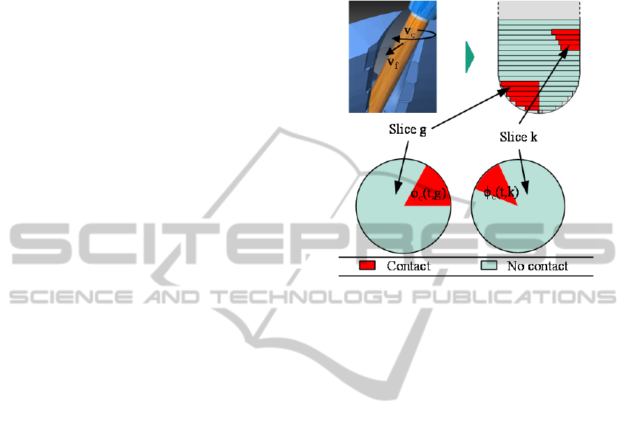
Figure 6
illustrates the definition of up-milling
(a) and down-milling (b) for a cutting tool rotating
clockwise. The contact in up-milling is in the 1
st
quadrant, and for down-milling is in the 2
nd
quadrant. The sense of rotation in macro-simulation
is recognized from the NC code, M03 for clockwise
rotation (CW) and M04 for counter-clockwise
(CCW) rotation. The engagement region between
the cutting tool and the workpiece lies in the 1
st
quadrant. The entry angle ϕ
st
can have the value 0°.
The value of exit angle ϕ
ex
should always be greater
than the entry angle ϕ
st
. The maximum allowable
value of the exit angle for up-milling is 90°. Hence
the value of the entry angle must be smaller than
90°. If the two values are equal then the contact
angle is zero (refer Equation (1)). Equations (4)-(7)
depict conditional definition for up-milling and
down-milling in macro-simulation for CW and
CCW rotations.
ϕ
st
ϵ (90°, 180°]
∧
ϕ
ex
ϵ (ϕ
st
°, 90°]
∧
M03 → Up-milling
(4)
ϕ
st
ϵ [0°, 90°)
∧
ϕ
ex
ϵ (ϕ
st
°, 90°]
∧
M04 → Up-milling
(5)
ϕ
st
ϵ [0°, 90°)
∧
ϕ
ex
ϵ (ϕ
st
°, 0°]
∧
M03 → Down-milling
(6)
ϕ
st
ϵ [90°, 180°)
∧
ϕ
ex
ϵ (ϕ
st
°, 180°]
∧
M04 → Down-milling
(7)
For a process designed as up-milling or down-
milling, if the position of the entry angle and the exit
angle are identified as ϕ
st
ϵ [0°,90°) and
ϕ
ex
ϵ (90°,180°] respectively and CW rotation, then
there is a transition in the cutting method from up-
milling to down-milling. The identified cutting
method due to such engagement condition is
undefined, and hence should be avoided.
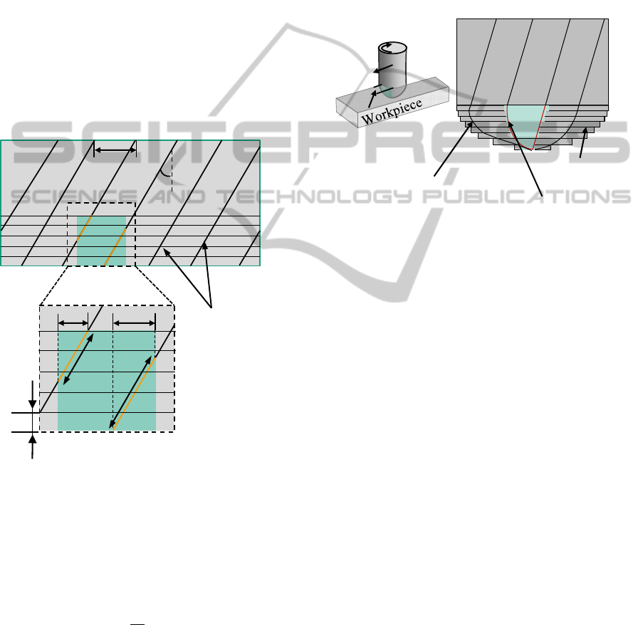
During multi-axis milling of turbine blades,
contact on radially opposite sides on the cutting
length of the cutting tool on different axial positions
is possible. This phenomenon is illustrated in
Figure 7. This leads to simultaneous up-milling and
down-milling. Although the CAM planning software
does not recognise this as an error, because contact
is only in the cutting length region of the cutting
tool, from a process technology point of view, it is a
critical phenomenon. The result is unpredictable
material removal and undefined mechanical load on
the cutting tool. To identify this phenomenon, the
cutting method on each of the tool slices in
engagement is identified. If the cutting method on
any pair of tool slices is inconsistent, i.e. different
cutting methods are identified on the slices in the
pair, simultaneous up-milling and down-milling is
identified. Also, if any slice has two separate
engagement regions, one in the up-milling and the
other in down-milling region, then there is a case of
simultaneous up- and down-milling.
Figure 7: Simultaneous up- and down-milling.
The tip of the ball end mill in engagement during the
process should be avoided (Ozturk, 2009). The
cutting velocity on the ball end mill is increasing on
the spherical part from a value 0 onwards due to
increasing radius along the cutting tool axis. The
zero cutting velocity at the tip results in no material
removal, and a rubbing action when in contact,
resulting in the increase in the temperature at the
cutting tool interface due to friction. In the macro-
simulation the engagement conditions are mapped
on the surface envelope of the cutting tool geometry.
Also the cutting tool is discretized into axial slices,
thus the tip of the cutting tool is contained in the
bottom-most tool slice (k=1). If the contact angle at
the bottommost tool slice is greater than 0° i.e.
(ϕ
c
(1) > 0°), the tip of the ball end mill is in
engagement.
With the identification of the cutting method,
undefined conditions such as transition of up-milling
to down-milling and simultaneous up- and down
milling can be identified during the CAM planning
stage. Thus resulting in elimination of critical
process conditions and increasing the process
reliability.
3.2 Mapping of Cutting Edge
Geometry in Macroscopic
Engagement Simulation
The mapping of cutting edges in the
ProcessCharacterizationandEvaluationofNCMachiningProcessesbasedonMacroscopicEngagementSimulation
665
macro-simulation enables determination of
engagement conditions for each individual cutting
edge for e.g. the contact length (l
c,i
) and the contact
angle on individual cutting edges (ϕ
c,i
) (refer
Figure 8).
In macro-simulation the engagement conditions
are mapped on the surface envelope of the cutting
tool. The information regarding the contact on the
rake faces of the cutting tool is not derivable (refer
Figure 4). For this reason the geometrical
parameters of the cutting edges which cannot be
mapped onto the surface envelope for e.g. rake
angle, flank angle etc. are not considered. In order to
map the cutting edges in the macro-simulation, two
parameters regarding the cutting edges are
necessary, namely the number of cutting edges Z,
and the helix angle of the cutting edges λ. (refer
Figure 8).
Figure 8: Engagement analysis for individual cutting
edges in the macro simulation result.
The number of cutting edges is given by Z and the
cutting edges are distributed with a constant offset
between consecutive cutting edges, this offset is
called as the angular pitch (ϕ
p
).it is calculated using
equation (8).
ϕ
p
=
2π
Z
(8)
The progression of the helix angle (λ) of the cutting
edges needs to be considered while mapping of
parameters in the macro simulation. The progression
of the helix angle is dependent on the tool shape.
The helix angle of the cutting edges of the
cylindrical end mill is constant along the axis of the
cutting tool, and thus on a 2D developed surface
model for the cylindrical end mill, the cutting edges
are linear (refer Figure 8). The diameter on the
spherical part of the ball end mill is variable along
the tool axis, hence the helix angle of the cutting
edge in case of a ball end mill is not constant along
the tool axis, but defined by a function
(Lazoglu, 2000).
Figure 9: Mapping of cutting edges on a 2D rolled out
model of ball end mill.
The spherical part is divided into slices of constant
diameter and the circumference of each tool slice is
mapped in the 2D rolled out model of a ball end
mill. Also the cutting edges for ball end mill start on
the tip of the ball end mill as illustrated in Figure 9.
The contact angle is assumed to be constant for each
tool slice. The helix angle is calculated for each tool
slice as a function of its axial position, and is
considered to be constant for each tool slice Δa
p
.
Hence the cutting edge is mapped as a straight line
on every tool slice. During mapping, the cutting
edges which are in contact can be marked as seen in
Figure 9.
The process condition illustrated in Figure 9 is an
elementary case of engagement between the cutting
tool and the workpiece. This engagement area can be
formally defined and mapped on the surface
envelope of the cutting tool. As illustrated in
Figure 10, the engagement area for a 5-axis milling
case of an impeller is mapped. It can be seen from
the figure that the engagement area is distorted and
cannot be defined formally. Also the contact on
individual cutting edges also cannot be defined
formally. To enable the mapping of the contact for
individual cutting edges, the contact angle calculated
for each tool slice is essential. The contact angle is
z=0
z=a
p
ϕ=360°
ϕ
st
ϕ
ex
ϕ=0°
Δa
p
l
c,3
l
c,4
ϕ
c,3
ϕ
c,4
λ
Cutting
edges
ϕ
p
2D rolled out model
Tool slice
Cutting edge in contact
(marked red)
Cutting edge in not contact
3D Model
v
f
v
c
a
e
Cutting tool
ICINCO2014-11thInternationalConferenceonInformaticsinControl,AutomationandRobotics
666
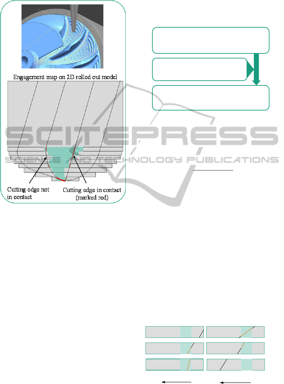
Figure 10: Mapping of microscopic parameters reflecting
contact conditions on a 2D rolled out model of ball end
mill.
then mapped on the tool surface envelope. The
position of the cutting edges mapped in the 2D
rolled out model of a cutting tool is considered to be
constant. Thus comparing the peripheral position of
the cutting edges and the contact angle for each tool
slice, the exact engagement for individual cutting
edge for every position along the cutting tool axis is
determined.
3.2.1 Derivable Microscopic Geometric
Parameters from Macroscopic
Engagement Analysis
With the information regarding the exact contact
conditions on individual cutting edges, geometric
quantities, such as the number of cutting edges in
contact, the contact length (L
sp
) and the uncut chip
geometry parameters such as the chip thickness (h
sp
),
the and the chip cross section area (A
sp
) can thus be
derived using the result of the macro simulation.
This is achieved by the extension of the macro
simulation as illustrated in Figure 11.
Figure 11: Determination of microscopic parameters in the
macro-simulation.
For a given contact angle ϕ
c
the contact length on
every tool slice is determined using the equation (9)
where r
T
is the cutting tool radius.
dl
s
(k)=
r
T
(ϕ
ex
(k)-ϕ
st
(k))
sin
λ
k
(9)
Six possibilities of contact on the cutting edge
(Altintas, 2012). are illustrated in Figure 12
for tool
slices, where ϕ
1,1
and ϕ
1,2
are the angular positions of
the cutting edges on the cutting tool periphery, the
part of the cutting edge in contact is coloured
orange, and the part not in contact is coloured black.
The exact contact length for each individual cutting
edge on each tool slice dl
s
(t,k) for every point on the
toolpath can be determined. The contact length l
s
(t)
for one cutting edge summed over all the tool slices
n is calculated using Equation (10):
l
s
t
=
dl
s
(
t,
k)
n
k=1
(10)
The total contact length for all cutting edges L
s
(t) at
every point on the toolpath is calculated using the
equation (11), where Z is the number of cutting
edges.
Figure 12: Cutting edge contact length for each tool slice.
Macro-simulation result
ϕ
st
(k) ϕ
ex
(k)ϕ
c
(k) r
T
(k)
Microscopic parameters
A
sp
L
sp
h
sp
Cutting edge geometry
Z
λ
(4)
z=0
z=Δa
p
z=0
z=Δa
p
z=0
z=Δa
p
ϕ
1,1
ϕ
1,2
ϕ
1,2
ϕ
1,1
(5)
(6)
ϕ=360° ϕ=0°
Direction of rotation
ϕ
st
ϕ
ex
ϕ
1,2
ϕ
1,1
ϕ
1,2
ϕ
1,2
ϕ
st
ϕ
ex
(1)
ϕ
1,1
(3)
Direction of rotation
ϕ=360° ϕ=0°
ϕ
1,2
ϕ
1,1
ϕ
1,1
(2)
ProcessCharacterizationandEvaluationofNCMachiningProcessesbasedonMacroscopicEngagementSimulation
667
L
s
(t)=
l
s,j
(t)
z
j=1
(11)
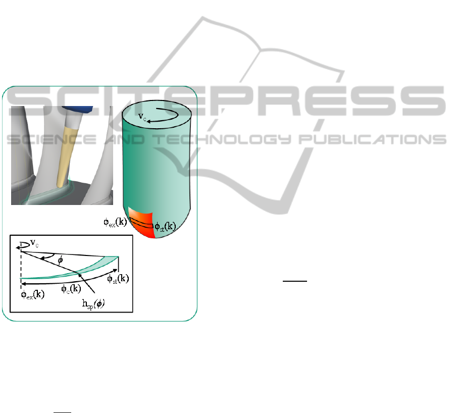
Figure (13) (a) illustrates a case of blisk machining
with a ball end milling cutter, (b) shows the
engagement field mapped on the tool surface
envelope. The contact angle is variable along the
cutting tool axis. The progression of the chip
thickness is illustrated in part (c) for a tool slice k.
The chip thickness according to Fischer’s approach
is calculated using equation (12). The chip thickness
h
sp
depends not only on the contact angle ϕ
c
but also
on the position of ϕ
st
and ϕ
ex
on the tool periphery.
The chip cross section area (A
sp
) also depends on the
ϕ
st
and ϕ
ex
. The chip cross-section area can be
determined using equation (13) (Meinecke, 2009)
respectively.
Figure 13: Progression of chip thickness over the contact
angle.
h
sp
=
f
z
sin(
ϕ
)d
ϕ
ϕ
ex
ϕ
st
(12)
A
D
sin
λ
h
,
,
d
(13)
Where, D is the cutting tool diameter, ϕ
1,j
and ϕ
2,j
are
the angular positions of the entry angle and the exit
angle of the cutting edges. And
ϕ
is the tool rotation
angle as depicted in Figure 13. From the contact
angle calculated for every tool slice and the cutting
edge helix angle, the progression of the chip
thickness and chip cross section area for each tool
slice can be calculated. This enables determination
of local uncut chip geometry parameters.
The cutting edges enter and leave the
engagement area due to the rotation of the cutting
tool, resulting in the variation of the contact length
and chip cross section area. The rotation of the tool
can be simulated by iterating the values of ϕ
st
and ϕ
ex
from 0° to 360°, and thus the variation in contact
length of the tool and the chip cross section area at a
point on the tool path can be analysed. This variation
in the values of the geometrical microscopic
parameters can be used for characterization of NC
machining processes based on process technology
values. Moreover, it can be evaluated if the
instantaneous values of the process technology
parameters are exceeding the minimum and the
maximum values decided during process design.
3.3 Process Characterization
Parameter based process characterization
The microscopic geometric quantities related to the
uncut chip determined on the basis of macroscopic
parameters (refer
subsection 3.2.1
), have direct co-
relation to process technology parameters. Due to
which, the magnitude of the microscopic geometric
parameters is indicative of the magnitude of the
process technology parameters for e.g. cutting force
F
c
, facilitating the parameter based characterization
of NC machining processes.
The cutting forces F
c
can be determined using
equation (14):
F
c
=
r
T
×K
c
tanλ
h
sp
ϕ
d
ϕ
ϕ
ex,j
ϕ
st,j
Z
j=1
(14)
where K
c
is an empirical constant calculated
experimentally and
ϕ
is the tool rotation angle.
Considering a case of a mould machining process
designed for a constant axial depth of cut, i.e. for
constant tool load, the complex toolpath geometry
results in varying engagement conditions along the
toolpath and thus varying loads. The relation
between the cutting forces and the chip thickness
enables process characterization based on chip
thickness. During process design, an optimal value
of the chip thickness is decided considering the tool
load. On one hand, exceeding of this set optimal
value results in tool overload. Thus the maximum
allowable feed f
z,max
per cutting edge for a point on
the tool path depends on the instantaneous contact
angle, which is dynamically changing. On the other
hand, during chip formation, if the value of feed per
cutting edge f
z
is too low for the instantaneous
ICINCO2014-11thInternationalConferenceonInformaticsinControl,AutomationandRobotics
668
contact angle, then a chip is never formed, and there
is ploughing effect due to rubbing action between
the cutting tool and workpiece, due to the friction
the temperature at the cutting tool workpiece
interface increases, leading to tool wear (Klocke,
2011). This phenomenon can be identified in the
macro simulation. The minimum allowable value of
feed per tooth, is the one which allows for formation
of chip, i.e. the cutting edge radius (Degner, 1973).
Thus, the value of minimum chip thickness is
constant throughout the process, whereas the value
of minimum feed per tooth f
z,min
is variable along the
toolpath, due to dynamic nature of the changing
contact angle. Any value of the feed per tooth
between f
z,min
and f
z,max
is acceptable but there is loss
in productivity. The conditional equation for
evaluation of processes based on feed per tooth as a
characterization parameter is shown in
equations (15)-(17).
f
z
(t) < f
z,min
(t) ∨f
z
(t) > f
z,max
(t) →
Unacceptable chip thickness
(15)
f
z,min
(t) < f
z
(t) < f
z,max
(t) → Acceptable chip
thickness
(16)
f
z
(t) = f
z,max
(t) → Optimal chip thickness (17)
During NC machining, multiple cutting edges are in
contact with the workpiece. Due to the rotation of
the cutting tool, the cutting edges enter and leave the
contact region, resulting in the fluctuation of load on
the cutting tool. When a cutting edge exits contact
and at the same moment, another cutting edge enters
contact, there is low fluctuation of cutting forces.
This condition is defined as Uniformity.
Engagement conditions leading to a low fluctuation
in the cutting load are preferred, since this helps in
an optimal process design. Uniformity is defined in
equation (18) (Kronenberg, 1969)
(18)
where n is an integer, l
arc
the contact arc length and
ϕ
p
the angular pitch of the cutting tool. C. Gey
conducted experiments and concluded that when
U=1 there is a local reduction in the cutting forces
(Gey, 2002). There is no variation in the value of
chip cross section area and the contact length.
Uniformity can be used for NC machining process
characterization, as fluctuation in load on cutting
tool is reflected by fluctuation in value of
microscopic geometric parameters. The variation in
chip cross section area (A
sp
) due to tool rotation can
be used as a metric to measure U, given by
equation (19) (Meinecke, 2009).
min
max
(19)
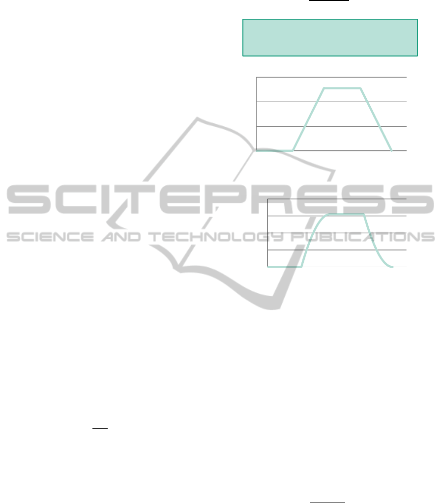
Figure 14: Progression of A
sp
, L
sp
for one cutting edge
with tool rotation.
During milling, when the contact angle for an
individual cutting edge increases as the cutting tool
rotates, the contact length increases linearly,
whereas the increase in chip cross section area is
digressive (refer Figure 14). Thus the contact length
can also be used to measure Uniformity, and to
derive information regarding the process dynamics.
For a cutting tool with multiple cutting edges in
engagement, for one complete rotation, due to the
individual cutting edges entering and exiting the
contact area, the total contact length L
s
. Thus
equation (20) depicts Uniformity measured on the
basis of the total contact length.
min
max
(20)
4 CONCLUSION
The high manufacturing costs involved in the multi-
axis machining of components having free form
surfaces makes it imperative to meet the highest
0
2
4
6
0 50 100 150 200
Contact Length L
sp
[mm]
Tool rotation Φ [°]
D
T
= 10 mm
Z = 4
λ = 45°
ϕ
c
= 44°
f
z
= 0.035 mm
0,00
0,02
0,04
0,06
0,08
0100200
Chip cross-section area A
sp
[mm
2
]
Tool rotation Φ [°]
0.08
0.04
0.00
ProcessCharacterizationandEvaluationofNCMachiningProcessesbasedonMacroscopicEngagementSimulation
669

quality with minimum effort. Moreover, a short
product life cycle leads to frequent design changes.
This increases the challenge on the process designers
to setup fault free processes the first time right. The
macro simulation tool provides an opportunity to
analyse and optimize the machining processes.
In the macro simulation, the macroscopic
engagement is calculated on the discrete points of
the toolpath. Using these calculated macroscopic
engagement conditions, interpretations regarding the
real process conditions can be deduced. With an
extension of the macroscopic simulation, even
microscopic geometric process characteristics are
derived. Thus NC machining processes can be
characterized based on purely macroscopic and
microscopic geometrical parameters which are
derived using the macroscopic engagement
parameters. Further this process analysis is
independent of empirical process data.
Prediction of the critical sections on the toolpath,
where the process technology values can exceed the
allowable limits set during process design, is
possible. Through the proactive identification of the
critical process sections, their elimination at the
process design phase is possible before the
machining processes are executed, thereby reducing
potential expensive damages and machine
downtime. Moreover there is improvement in the
process reliability. Thus there is optimization in the
productivity of the NC machining processes.
ACKNOWLEDGEMENTS
The authors would like to thank the German
Research Foundation DFG for the support of the
depicted research within the Cluster of Excellence
"Integrative Production Technology for High-Wage
Countries".
REFERENCES
Altintas, Y., 2012, Manufacturing automation: Metal
cutting mechanics, machine tool vibrations, and CNC
design, 2nd edn., Cambridge University Press,
Cambridge, New York.
Bouzakis, K.-D., Michailidis, N., Gerardis, S.,
Katirtzoglou, G., Lili, E., Pappa, M., Brizuela, M.,
Garcia-Luis, A. & Cremer, R., 2008, ‘Correlation of
the impact resistance of variously doped CrAlN PVD
coatings with their cutting performance in milling
aerospace alloys’, Surface and Coatings Technology
203(5-7), 781–785.
Choi, B.K. & Jerard, R.B., 1998, Sculptured surface
machining: Theory and applications, Kluwer
Academic, Dordrecht, London.
Degner, W., Ham, N. C., Untersuchungen beim spanen
mit kleinen spanungsdicken, Fertigungstechnik und
Betrieb 13 (1973), 523 – 528.
Gey, C., 2002, Prozessauslegung für das Flankenfräsen
von Titan, VDI-Verl., Düsseldorf.
Hoischen, H., 2003, Technisches Zeichnen: Grundlagen,
Normen, Beispiele, darstellende Geometrie ; ein Lehr-
, Übungs- und Nachschlagebuch für Schule,
Umschulung, Studium und Praxis, 29th edn.,
Cornelsen Girardet, Berlin.
Klocke, F., 2011, Manufacturing Processes, Springer,
Berlin, Heidelberg, New York.
Kronenberg, M., 1969, Grundzüge der Zerspanungslehre:
Theorie und Praxis der Zerspanung für Bau und
Betrieb von Werkzeugmaschinen, 2nd edn., Springer,
Berlin [etc.].
Lazoglu, I. & Liang, S. Y., 2000, ‘Modeling of Ball-End
Milling Forces With Cutter Axis Inclination’, Journal
of Manufacturing Science and Engineering 122(1), 3.
Meinecke, M., 2009, Prozessauslegung zum fünfachsigen
zirkularen Schruppfräsen von Titanlegierungen,
Apprimus-Verl., Aachen.
Minoufekr, M., Glasmacher, L., Adams, O., ‘Macroscopic
Simulation of Multi-axis Machining Processes’, 10th
International Conference on Informatics in Control,
Automation and Robotics (ICINCO 2013), 505–516.
Ozturk, E., Tunc, L. T. & Budak, E., 2009, ‘Investigation
of lead and tilt angle effects in 5-axis ball-end milling
processes’, International Journal of Machine Tools
and Manufacture 49(14), 1053–1062.
Schug, P. et al, 2012, Durchgängige CAx-Prozessketten,
Forschung an der Werkzeugbau Akademie, Apprimus,
Aachen.
Zabel, A., 2010, Prozesssimulation in der Zerspanung,
Vulkan-Verlag, Dortmund.
ICINCO2014-11thInternationalConferenceonInformaticsinControl,AutomationandRobotics
670
