
Analysis of Possible Exploitation for Long Reach Passive
Optical Networks
Rastislav Róka
Institute of Telecommunications, Slovak University of Technology, Ilkovičova 3, 812 19 Bratislava, Slovakia
Keywords: LR-PON Network, HPON Network Configurator, EPON, 10G-EPON, GPON and XG-PON
Implementations.
Abstract: For the expansion of networks based on optical transmission media, it is necessary to have a detailed
knowledge of advanced implementations for passive optical systems used in the access network. This
contribution shortly discusses possible scenarios of exploitation for hybrid passive optical networks. A main
part is focused on characteristics of the HPON network simulation environment and on results from
simulation experiments related to the Long Reach Passive Optical Network effective utilization for various
higher layers.
1 INTRODUCTION
Next Generation Passive Optical Networks (NG-
PON) present optical access infrastructures to
support various applications of many service
providers. In the near future, we can expect NG-
PON technologies with different motivations for
developing Hybrid Passive Optical Networks
(HPON). The HPON is a hybrid network in a way
that utilizes on a physical layer both Time- (TDM)
and Wavelength- Division Multiplexing (WDM)
principles together (Róka, 2012). Moreover, the
HPON presents a hybrid network as a necessary
phase of the future transition from TDM to WDM
passive optical networks (Peťko, 2012). Possible
exploitation of hybrid passive optical networks can
be divided into four probable scenarios:
In the first case, the WDM/TDM PON
network represents a hybrid network based
on the combined WDM/TDM approach.
The WDM/TDM PON architecture
associates several smaller TDM networks
into one large network, where each TDM
network utilizes specific wavelength for
communication with the Optical Line
Terminal (OLT). A number of subnetworks
depends on a number of Array Waveguide
Gratings (AWG) ports, when every
subnetwork can utilize different splitting
ratio.
In the second case, a change of OLT and
ONU equipment is executed and adding of
both (WDM and TDM) Optical Network
Unit (ONU) equipment into common
network architecture is allowed by using
specialized remote nodes that utilize either
passive optical power splitters or AWG
elements. By this way, a smooth transition
from TDM to WDM networks is allowed.
As an example, the SUCCESS (Stanford
University aCCESS) HPON can be
presented (An, 2005; Kazovsky, 2011). The
SUCCESS HPON network introduces a
sequential transition to the pure WDM
PON network in a compliance with the
TDM and WDM technology coexistence.
The hybrid SUCCESS architecture
comprises the ring topology for the WDM
transmission. It contains two types of
Remote Nodes (RN) for the WDM or TDM
star connections. The WDM RN is created
from AWG elements, the TDM RN from
optical power splitters. The OLT terminal
generates signals for both WDM and TDM
ONU units by means of Dense WDM
(DWDM) wavelengths; however the TDM
ONU transmits signals on Coarse WDM
(CWDM) wavelengths. This architecture
allows provisioning WDM services at
preservation of the backward compatibility
195
Róka R..
Analysis of Possible Exploitation for Long Reach Passive Optical Networks.
DOI: 10.5220/0005054101950202
In Proceedings of the 4th International Conference on Simulation and Modeling Methodologies, Technologies and Applications (SIMULTECH-2014),
pages 195-202
ISBN: 978-989-758-038-3
Copyright
c
2014 SCITEPRESS (Science and Technology Publications, Lda.)

with initial/original TDM subscribers. The
exchange of the TDM ONU is necessary.
Information can be found in (Róka, 2014).
In the third case, a scope is to create a
modular network and to enable service
provisioning for more than 1000
subscribers at distances up to 100 km using
the SARDANA (Scalable Advanced Ring-
based passive Dense Access Network
Architecture) design (Kazovsky, 2011;
Lazaro, 2008). It is considered a remote
pumped amplification using Erbium Doped
Fiber Amplifier (EDFA) principles and a
utilization of the colorless ONU units at
subscriber side. Also, the backward
compatibility with existing 1G-PON
networks and a support for standardized
10G-PON networks are considered with
100-1000 Mbit/s transmission rates per one
subscriber. The PON fiber topology is
creating by two main parts – the WDM ring
with the central office and remote nodes,
TDM trees connected to particular remote
nodes. The WDM ring consists of two
optical fibers – one per direction. A key
element of the network is the RN. Used
ONU units are colorless; they don’t contain
any optical source. Transmitting from the
ONU is based on the Reflective
Semiconductor Optical Amplifier (RSOA)
by means of the re-modulation of received
signals. The SARDANA network allows
connecting a large number of subscribers
either on smaller distance in populous
urban areas or in larger geographical areas
with small population. Information can be
found in (Róka, 2014).
In the fourth case, the Long Reach Passive
Optical Network (LR-PON) architecture
utilizes active components in an outside
plant (Prat, 2009). A network reach can be
extended up to 100 km and can be utilized
various type of optical amplifiers – EDFA,
RAMAN, SOA. A network attenuation
depends on a type of optical fibers, on a
selected TDM network, on a number of
connected subscribers and on a distance
OLT–ONU.
In this paper, analysis of possible exploitation
for only Long Reach Passive Optical Networks is
presented. Also, effective utilization of the LR-PON
for various higher layers of the Open Systems
Interconnection (OSI) model is examined and
verified. Analysis of other hybrid passive optical
networks using the HPON Network Configurator
can be found in (Róka, 2013).
2 THE SIMULATION
ENVIRONMENT FOR HPON
NETWORKS
Our simulation model for comparing possible
exploitations of various scenarios in real access
networks is created by using the Microsoft Visual
Studio 2008 software in the IDE development
environment (Róka, 2011, 2012, 2013). There exist
possibilities for the graphical interface created by
using the Microsoft Foundation Class (MFC) library
for the C++ programming language. The simulation
model has one main dialogue window for simulating
a transition from TDM-PON to HPON networks. It
allows comparing principal approaches for
configuring of hybrid passive optical networks. A
cut-out from the main window of the HPON
Network Configurator is shown on Fig. 1.
The HPON simulation environment is working
in several steps:
1. Setting parameters of the optical fiber – a
type of the optical fiber (according to the
ITU-T), the DWDM multiplexing density.
2. Evaluating optical fibers – standard or
inserted specific attenuation values in
[dB/km], a calculation of numbers of
CWDM and DWDM carrier wavelengths.
3. Inserting input parameters of the TDM-
PON network - a number of TDM
networks, a type of the network, a number
of subscribers per one network, a distance
between the ONT and the OLT.
4. Evaluating input parameters – a calculation
of the total transmission capacity of the
TDM network together with the average
capacity per one subscriber, the total
number of subscribers and the maximum
attenuation of the TDM network; also, the
attenuation class is presented. This step is
terminating with the selection of detailed
hybrid PON configuration design.
SIMULTECH2014-4thInternationalConferenceonSimulationandModelingMethodologies,Technologiesand
Applications
196
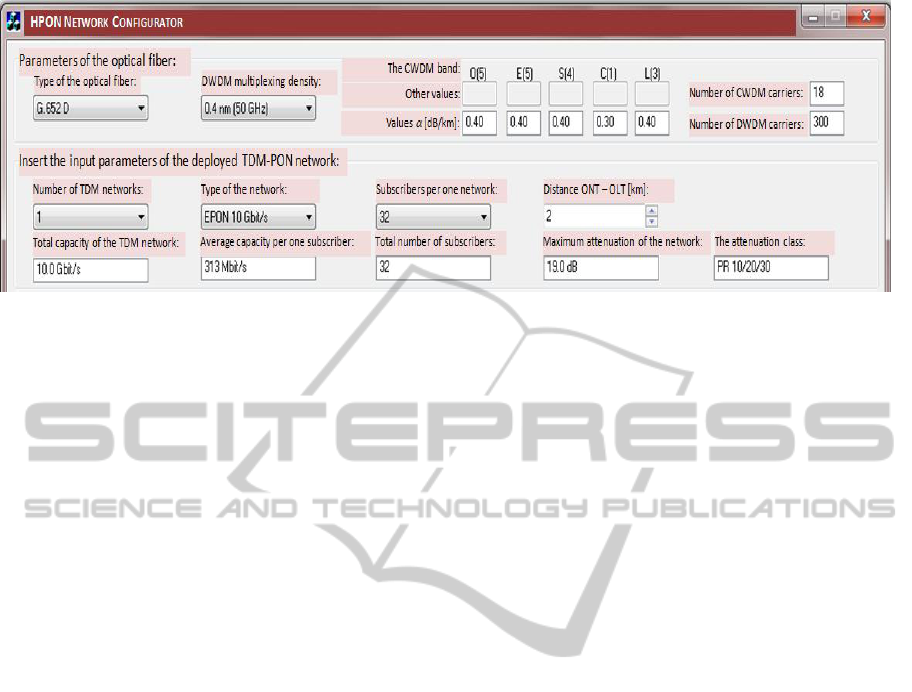
Figure 1: The cut-out from the main window of the HPON Network Configurator.
5. Setting input parameters for the hybrid
PON configuration – based on the stored
TDM-PON network data and selecting one
from HPON types.
6. Application input parameters and specific
network parameters of the HPON
configuration (the total capacity of the
hybrid network, the total number of
subscribers, the average capacity per one
subscriber, the maximum attenuation of the
hybrid network between the OLT and the
ONT, a number and type of used active and
passive components) with summing up a
type and number of deployed optical
components and presenting possibilities for
future expanding of hybrid HPON network
types.
At first, a selection of the optical fiber’s type and
the DWDM multiplexing density can be executed. A
selected type of the optical fiber is presented by the
specific attenuation values and by a number of
transmission bands. These values correspond to
various ITU-T recommendations – ITU-T G.652 A,
G.652 B, G.652 C, G.652 D, G.656, G.657 – and, if
available, measuring data can be inserted in the
“Other values” option. Then, specific attenuation
coefficients are used for calculating the optical
fiber`s attenuation in corresponding bands in
specific network configurations. Also, a total
number of CWDM and DWDM carrier wavelengths
for particular bands is presented. The relationship
between numbers of available wavelengths at
various channel allocations is introduced in (Róka,
2012).
Following, a specification of parameters and
features of the deployed TDM-PON network is
presenting. More detailed information about analysis
of various hybrid passive optical networks using the
HPON Network Configurator can be found in
(Róka, 2013).
3 POSSIBILITIES OF THE LR-
PON NETWORK
In the latest scenario of the possible HPON
exploitation, the Long Reach PON utilizes moreover
active components (optical amplifiers) that can
extend a network reach or improve splitting ratio in
remote nodes. The Long Reach PON window is
opened (Fig. 2). In the HPON Network
Configurator, options for selecting a higher splitting
ratio (1:128 and more) are supplemented as a special
feature of the LR-PON. When one of higher
splitting ratios of subscribers per network is
selected, options for configuration of other hybrid
passive optical networks - WDM/TDM PON,
SUCCESS HPON and SARDANA HPON - are
automatically deactivated because they don’t
support this selected splitting ratio. For this case, an
option for the Long Reach PON configuration is
only active.
Possibilities for new configuration of this LR-
PON network are very similar to the hybrid
WDM/TDM PON network configuration. One
option for selecting of specified optical amplifiers
type is supplemented as a main factor that
distinguished the LR-PON from other passive
optical networks (Fig. 3).
In the LR-PON network, a selection from three
types of optical amplifiers – Erbium Doped Optical
Amplifier (EDFA), Raman Amplifier (RAMAN)
and Semiconductor Optical Amplifier (SOA) –
located in the OLT is possible.
AnalysisofPossibleExploitationforLongReachPassiveOpticalNetworks
197
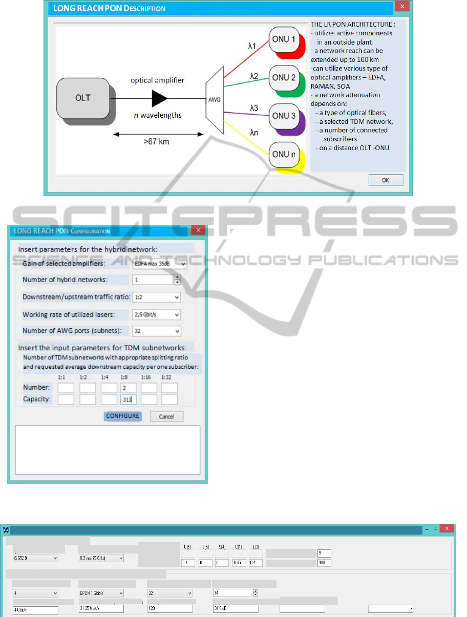
Figure 2: The opening window of the Long Reach PON network approach.
Figure 3: The Long Reach PON network configuration
window.
These optical amplifiers have various features and
characteristics and different values of the optical
amplification (gain)
In the LR-PON network, a selection from three
types of optical amplifiers – Erbium Doped Optical
Amplifier (EDFA), Raman Amplifier (RAMAN)
and Semiconductor Optical Amplifier (SOA) –
located in the OLT is possible. These optical
amplifiers have various features and characteristics
and different values of the optical amplification
(gain). Options of appropriate optical amplifiers type
are depending on specified network configurations.
In a case of mismatched network configuration
or/and parameters setting, error messages are
presented in the bottom part of the LR-PON
configuration window (Fig. 3). A summary of
selected parameters for mentioned optical amplifiers
is introduced in Table 1.
Figure 4: The window with the EPON input parameters.
HPON NETWORK CONFIGURATOR
Parameters of the optical fiber:
Type of the optical fiber: DWDM multiplexing
dit
N
umber of CWDM carriers:
The CWDM band:
N
umber of DWDM carriers:
Other values:
Values
[dB/km]:
Insert the input parameters of the deployed TDM-PON network:
Nu
mber of TDM networks:
Type of the network: Subscribers per one network: Distance ONT – OLT [km]:
Total capacity of the TDM network:
Average capacity per one subscriber:
Total number of subscribers:
Maximum attenuation of the network:
The attenuation class:
invalid Use the LR-PON
SIMULTECH2014-4thInternationalConferenceonSimulationandModelingMethodologies,Technologiesand
Applications
198

Table1: Parameters of optical amplifiers in the LR-PON
networks.
Features EDFA Raman SOA
Gain [dB] up to 35 up to 25 up to 30
Wavelength band
[nm]
1530 – 1560
1280 –
1650
1280 –
1650
Noise figure
[dB]
5 5 8
Cost medium high low
4 RESULTS OF SIMULATION
EXPERIMENTS
For higher layers of the OSI model, there exist
different implementations for deployed TDM-PON
networks. First, the GPON (Gigabit-capable PON)
option based on the FSAN initiative was
standardized as the ITU G.984 in 2003 (ITU-T,
2008). Second, the EPON (Ethernet PON) option
independent on previous one based on the Ethernet
protocol was standardized as the IEEE 802.3ah in
2004 (IEEE, 2004). The GPON works with higher
downstream/upstream rates than the EPON,
moreover has better network performance
relationships for connecting higher number of
subscribers and for longer distances.
Latter recommendations are IEEE 802.3av
(IEEE, 2009) and ITU-T G.987 (ITU-T, 2010,
2012). The 10G-EPON works at 10 Gbit/s rates.
Besides another features, various attenuation classes
are defined for higher splitting ratios and for longer
distances. Depending on selected attenuation
classes, demands for the optical laser in the OLT
and receivers in ONUs are specified for the
downstream signal transmission. Reciprocally,
options for utilization of optical lasers in ONUs and
the receiver in the OLT are characterized for the
upstream signal transmission.
The XG-PON also works at 10 Gbit/s rates.
Besides another features, changes of attenuation
classes comparing to the GPON are realized due to
overrun original attenuation classes by using the
WDM filter and different wavelengths. There are
standardized 2 Nominal attenuation classes and 2
Extended attenuation classes.
Except above-mentioned case with the higher
splitting ratio of subscribers, options for
configuration of other hybrid passive optical
networks - WDM/TDM PON, SUCCESS HPON
and SARDANA HPON - are automatically
deactivated also in a case of overrunning the
maximum network attenuation value. This value is
depending on the optical fibers’ type, the network
type, a number of subscribers and the OLT-ONT
distance. Also for this case, only a challenge for the
Long Reach PON configuration is appearing. On
Fig. 4, we can see a cut-out from the main window
of the HPON Network Configurator with EPON
input parameters for the deployed TDM-PON
network.
HPON
N
ETWORK
C
ONFIGURATOR
Parametersoftheopticalfiber:
Typeoftheopticalfiber: DWDMmultiplexingdensity:
NumberofCWDMcarriers:
TheCWDMband:
NumberofDWDMcarriers:
Othervalues:
Values
[dB/km]:
InserttheinputparametersofthedeployedTDM‐PONnetwork:
Numberof
T
DMnetworks:
Typeofthenetwork: Subscribersperonenetwork: DistanceONT
–
OLT[km]:
TotalcapacityoftheTDMnetwork:
Averagecapacityperonesubscriber:
Totalnumberofsubscribers:
Maximumattenuationofthenetwork:
Theattenuationclass:
UsetheLR‐PONinvalid
Figure 5: The window with the 10G-EPON input parameters.
HPON
N
ETWORK
C
ONFIGURATOR
Parametersoftheopticalfiber:
Typeoftheopticalfiber: DWDMmultiplexingdensity:
NumberofCWDMcarriers:
TheCWDMband:
NumberofDWDMcarriers:
Othervalues:
Values
[dB/km]:
InserttheinputparametersofthedeployedTDM‐PONnetwork:
Numberof
T
DMnetworks:
Typeofthenetwork: Subscribersperonenetwork: DistanceONT
–
OLT[km]:
TotalcapacityoftheTDMnetwork:
Averagecapacityperonesubscriber:
Totalnumberofsubscribers:
Maximumattenuationofthenetwork:
Theattenuationclass:
UsetheLR‐PONinvalid
Figure 6: The window with the GPON input parameters.
AnalysisofPossibleExploitationforLongReachPassiveOpticalNetworks
199
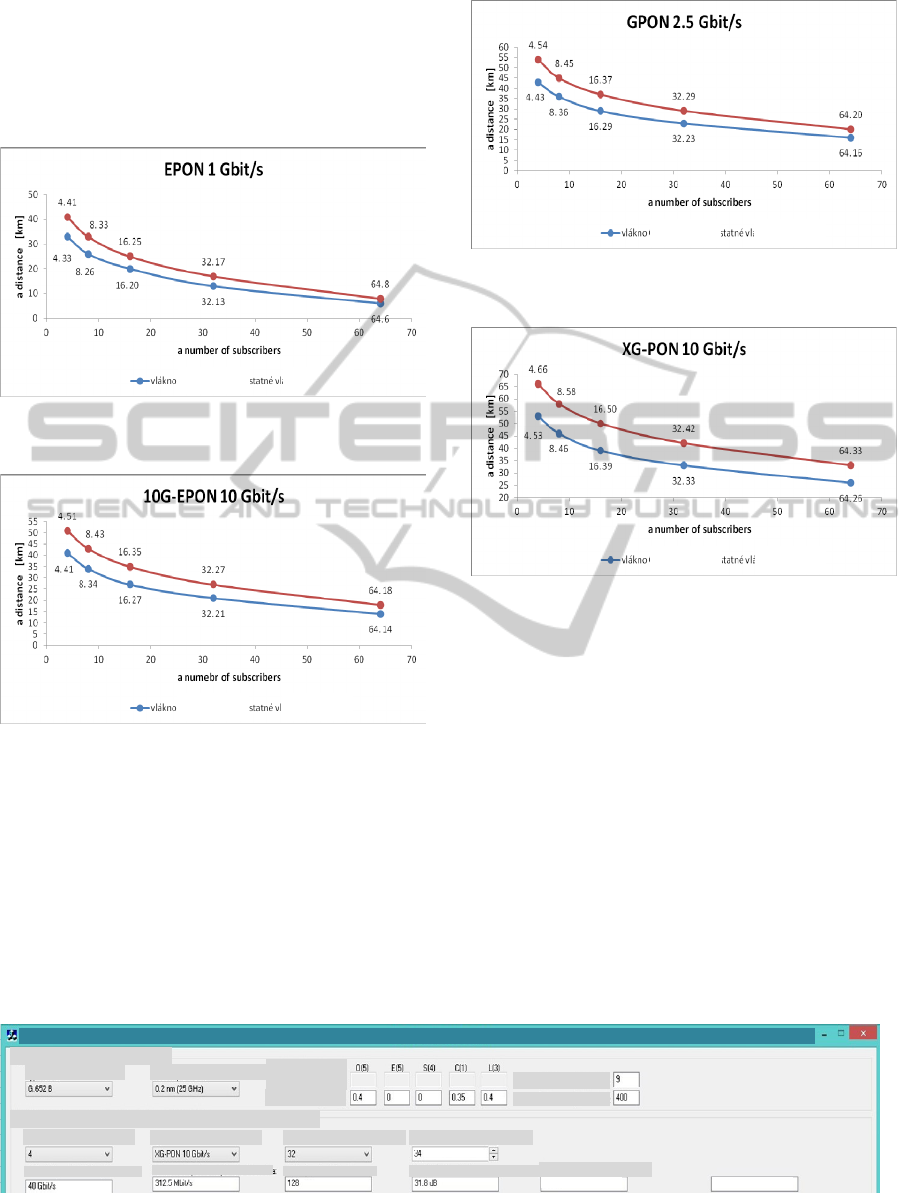
Affiliated with these parameters, limits of
exploitation for the LR-PON are presented on Fig. 8,
where the blue line is reserved for the G. 652 A
optical fiber and the red line is assigned for others
(G. 652 B, G. 652 C, G. 652 D, G. 656, G. 657) with
identical attenuation values.
Figure 8: Limits for the Long Reach PON utilization for
the EPON 1 Gbit/s.
Figure 9: Limits for the Long Reach PON utilization for
the 10G-EPON 10 Gbit/s.
In a case of the 10G-EPON network, affiliated
with its input parameters (Fig. 5), limits of
exploitation for the LR-PON are presented on Fig. 9.
As can be seen, distances are longer than at the
EPON due to adapted attenuation classes of the
latter10G-EPON network in spite of its higher
transmission rates.
Figure 10: Limits for the Long Reach PON utilization for
the GPON 2,5 Gbit/s.
Figure 11: Limits for the Long Reach PON utilization for
the XG-PON 10 Gbit/s.
In a case of the GPON network, affiliated with
its input parameters (Fig. 6), of exploitation for the
LR-PON are presented on Fig. 10. As can be seen,
distances are longer than at the EPON due to better
performance relationships of the GPON network in
spite of its higher transmission rates.
In a case of the XG-PON network, affiliated with
its input parameters (Fig. 7), limits of exploitation
for the LR-PON are PON are presented on Fig. 11.
As can be seen, distances are the longest between
considered implementations of the deployed TDM-
PON network due to more precisely adapted
attenuation classes in spite of its higher transmission
rates.
HPON
N
ETWORK
C
ONFIGURATOR
Parametersoftheopticalfiber:
Typeoftheopticalfiber: DWDMmultiplexingdensity:
NumberofCWDMcarriers:
TheCWDMband:
NumberofDWDMcarriers:
Othervalues:
Values
[dB/km]:
InserttheinputparametersofthedeployedTDM‐PONnetwork:
Numberof
T
DMnetworks:
Typeofthenetwork: Subscribersperonenetwork: DistanceONT
–
OLT[km]:
TotalcapacityoftheTDMnetwork:
Averagecapacityperonesubscriber:
Totalnumberofsubscribers:
Maximumattenuationofthenetwork:
Theattenuationclass:
UsetheLR‐PONinvalid
Figure 7: The window with the XG-PON input parameters.
G.652A
o
p
tical fibe
r
other
o
p
tical fibe
r
s
G.652A
o
p
tical fibe
r
other
o
p
tical fibe
r
s
G.652A
o
p
tical fibe
r
other
o
p
tical fibe
r
s
G.652A
o
p
tical fibe
r
other
o
p
tical fibe
r
s
SIMULTECH2014-4thInternationalConferenceonSimulationandModelingMethodologies,Technologiesand
Applications
200

On Fig. 12, a comparison of limits for
employment of the Long Reach PON is presented for
particular PON networks and for various types of
optical fibers.
Figure 12: The comparison of limits for the Long Reach
PON utilization for particular PON networks.
5 CONCLUSIONS
For given environment of the LR-PON networks,
different implementations for higher layers of the
OSI model in the deployed TDM-PON network were
compared. From presented results, the XG-PON
network with the 10 Gbit/s transmission rates can
reach qualitative better values. However, using of
concrete implementation (EPON, 10G-EPON,
GPON, XG-PON) for higher layers is depending on
many factors, for example the distance between OLT
and particular ONUs in km, the total number of
subscribers, the maximum attenuation of the network
and the attenuation class.
6 FUTURE WORK
In the near future, possibilities of the HPON Network
Configurator will be expanded into the area of mutual
comparison for deployed optical components and
possible expansions of four probable scenarios of
hybrid passive optical networks. Moreover,
extensions related with the traffic protection and
restoration for each particular HPON network type
will be proposed and prepared.
Inseparable part of the future work is searching
for appropriate and competent results of scientific
and industrial projects for preparing valuable
comparative evaluation.
ACKNOWLEDGMENT
This work is a part of research activities conducted at
Slovak University of Technology Bratislava, Faculty
of Electrical Engineering and Information
Technology, Institute of Telecommunications, within
the scope of the project KEGA No. 039STU-4/2013
“Utilization of Web-based Training and Learning
Systems at the Development of New Educational
Programs in the Area of Optical Transmission
Media”.
REFERENCES
Róka, R., May 2012. Fixed Transmission Media. In:
Technology and Engineering Applications of Simulink,
InTech, Rijeka (Croatia), ISBN 978-953-51-0635-7.
Peťko, L., October 2012. G-PON Migration to New
Technologies. In: OK 2012 - 15
th
Conference and
Exhibition on Optical Communications, Praha (Czech
Republic), ISBN 978-80-86742-36-6.
An, F. et al., November 2005. SUCCESS-HPON: A Next-
Generation Optical Access Architecture for Smooth
Migration from TDM-PON to WDM-PON. In: IEEE
Communications Magazine, Vol.43, No.11, pp. S40-
S47.
Kazovsky, L., 2011. Broadband optical access networks:
emerging technologies and optical-wireless
convergence. In: Wiley-Interscience, Hoboken, N.J.
ISBN 978-047-0182-352.
Róka, R., 2014. Broadband NG-PON Networks and their
Designing using the HPON Network Configuration. In:
Convergence of Broadband, Broadcast and Cellular
Network Technologies, IGI Global - in the printing
process.
Lazaro, J. et al., 2008. Scalable Extended Reach PON,
Optical Fiber Communication. In: OFC/NFOEC 2008 -
National Fiber Optic Engineers Conference, pp. 1-3.
Prat, J. et al., 2009. Passive Optical Network for Long-
reach Scalable and Resilient Access. In: ConTEL 2009
- 10
th
International Conf. on Telecommunications, pp.
271-275.
Róka, R., August 2011. The Extension of the HPON
Network Configurator at Designing of NG-PON
Networks. In: TSP 2011 – 34
th
International
Conference on Telecommunications and Signal
Processing. Budapest (Hungary), pp. 79-84, ISBN 978-
1-4577-1409-2.
AnalysisofPossibleExploitationforLongReachPassiveOpticalNetworks
201

Róka, R., June 2012. The Designing of NG-PON Networks
Using the HPON Network Configuration. In: Journal of
Communication and Computer JCC, Vol.9, No.6, pp.
669-678, print ISSN 1548-7709, online ISSN 1930-
1553.
Róka, R., September 2013. Analysis of Hybrid Passive
Optical Networks using the HPON Network
Configurator, In: INTECH 2013 – International
Conference on Innovative Technologies. Budapest
(Hungary), pp. 401-404, ISBN 978-953-6326-88-4.
Róka, R., Special Issue 2013. The Analysis of SUCCESS
HPON Networks using the HPON Network
Configurator. In: Advances in Electrical and Electronic
Engineering AEEE, Vol.11, No.5, pp. 420-425, ISSN
1336-1376, E-ISSN 1804-3119.
Róka, R., December 2013. The Analysis of SARDANA
HPON Networks using the HPON Network
Configurator. In: Advances in Electrical and Electronic
Engineering AEEE, Vol.11, No.6, pp. 522-527, ISSN
1336-1376, E-ISSN 1804-3119.
ITU-T Recommendation G.984.1, March 2008. Gigabit-
capable passive optical networks (GPON) - General
characteristics.
IEEE Standard 802.3ah, 2004. Telecommunications and
information exchange between systems - Local and
metropolitan area networks— Specific requirements -
Part 3: CSMA/CD Access Method and Physical Layer
Specifications Amendment.
IEEE Standard 802.3av, 2009. Telecommunications and
information exchange between systems - Local and
metropolitan area networks - Specific requirements
Part 3: CSMA/CD Access Method and Physical Layer
Specifications Amendment 1: Physical Layer
Specifications and Management Parameters for 10
Gb/s Passive Optical Networks.
ITU-T Recommendation G.987.1, April 2012. 10-Gigabit-
capable passive optical networks (XG-PON) - General
requirements.
ITU-T Recommendation G.987.2, October 2010. 10-
Gigabit-capable passive optical networks (XG-PON) -
Physical media dependent (PMD) layer specification.
SIMULTECH2014-4thInternationalConferenceonSimulationandModelingMethodologies,Technologiesand
Applications
202
