
Integration of Autonomic Mechanisms to a
Test Management Solution
Clauirton A Siebra and Natasha Q. C. Lino
Informatics Center, Federal University of Paraiba, Campus I, Joao Pessoa, Brazil
Keywords: Test Automation, Test Process Management, Intelligent Control.
Abstract: Testing is one of the most time-consuming phases of the software development cycle and this is not
different in the mobile software domain. In fact, small input mechanisms, dependence to wireless network
configurations and complex navigations create a very stressful and prone to errors test environment. This
paper presents additional modules that were specified to a test management tool, which extend its abilities in
terms of automation, intelligent control and statistical metrics manipulation. We compare this approach to
other efforts from the software engineering community and stress the gains in our test process. A list of
learned lessons was also consolidated to share important points of this experience.
1 INTRODUCTION
While number and complexity of tests are increasing
due to new resources provided by computational
platforms, test centers are forced to improve their
test process time. Note that as faster a specific
system is evaluated and delivered to the market, as
better will be its chances against other applications.
Thus this scenario configures a contradiction: the
need to increase the number of tests and decrease the
test time. Furthermore, this contradiction can lead to
reduce the quality of the overall test process.
The use of test management solutions, which are
able to support all the stages of a test cycle
(Aljahdali et al, 2012), is an option to ensure a better
control and quality of this process. There are several
options for management tools available in the
market (Chin et al, 2007). However, it is hard to
cover all the stages of the test process with a unique
tool, mainly if the test domain differs from the
traditional software development cycle. Considering
this fact, we have investigated and specified a test
architecture, which mainly focused on concepts of
automation. This architecture was carried out in a
modular way, so that each module could be
instantiated with third-party or home-made
solutions.
The remainder of this paper is organized as
follows: Section 2 presents an abstract view of our
test architecture, showing its modules and
communications among them. Section 3 discusses
our investigation about possible pre-defined
solutions/tools that could fit this test architecture,
stressing the gaps of such solutions. Section 4
describes additional components that were integrated
to the solution to cover such gaps. Section 5
comments the main learned lessons in terms of test
coverage, documentation and time efficiency.
Section 6 discusses previous works related to our
approach, while Section 7 concludes this work.
2 TEST ARCHITECTURE
Test management architectures can be seen as a set
of several different modules. Each of them is a
computational process that intends to perform a
function related to the whole test process. The
diagram in follow (Figure 1) shows an abstract view
of test management modules that were considered
important to our test process. This diagram stresses
six main test modules: Test Case (TC) Generation,
Mapping, Filter, Planning, Execution and Results.
TC Generation accounts for populating the TC
Database with test cases that validate the Domain
Specification (Yamaura, 1998). This module can be
an automatic process if the domain specification is
modelled in a formal way. There are some
approaches in this direction, which are mainly based
on formal methods (Prasanna et al, 2005).
269
Siebra C. and Q. C. Lino N..
Integration of Autonomic Mechanisms to a Test Management Solution.
DOI: 10.5220/0004989502690276
In Proceedings of the 9th International Conference on Software Engineering and Applications (ICSOFT-EA-2014), pages 269-276
ISBN: 978-989-758-036-9
Copyright
c
2014 SCITEPRESS (Science and Technology Publications, Lda.)
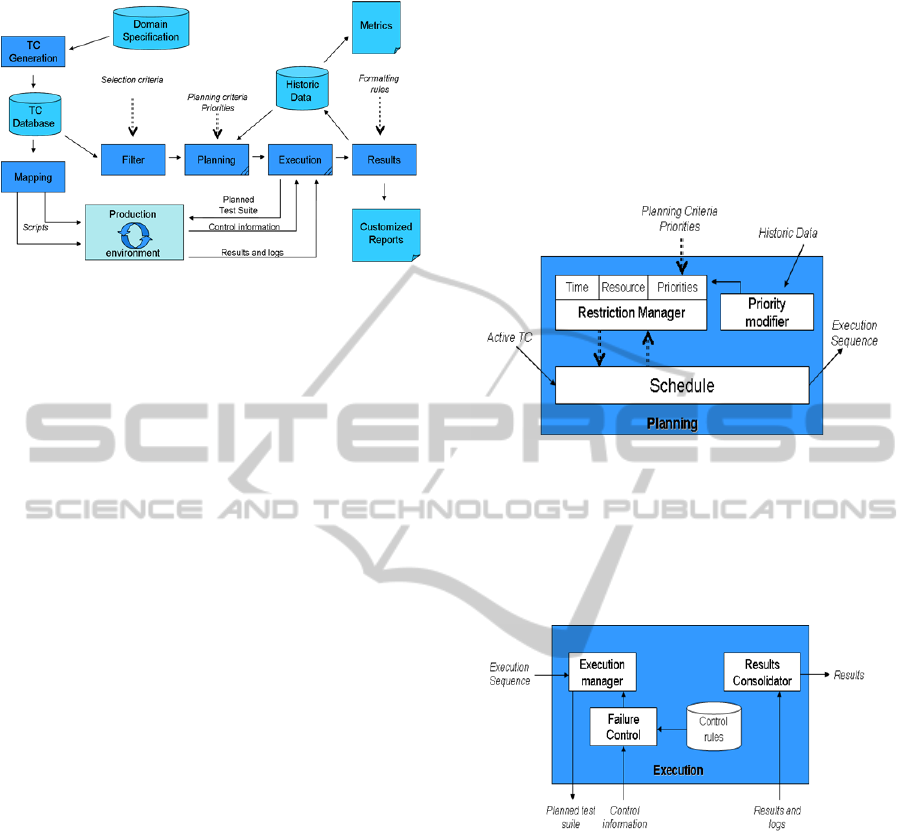
Figure 1: Test management architecture.
The Mapping module accounts for the
generation of scripts to be executed in a production
environment. Differently of test cases, which do not
usually change, the script language depends on the
environment where they are going to be executed.
The automatic generation of scripts can be carried
out using similar techniques than those used to TC
generation.
The Filter module accounts for selecting the test
cases that are going to be used in a test cycle,
according to some Selection Criteria. For example, a
product may not support certain function, so that all
the tests related to such function must be eliminated
from the active test suite.
The Planning module accounts for creating an
optimal sequence of tests (or plan of tests) based on
parameters such as Plan Criteria (time and
resources), Priorities (simple indications of test
ordering) and Historical Data rules (e.g., indications
of more problematic tests so that they can firstly be
carried out).
The Execution module accounts for the real
performance of pre-defined sequence of tests. To
that end, this module sends the planned test suite to
the production environment and monitors the
execution of this sequence via control information.
Control information is, for example, an indication
that a TC has failed. Then, the execution module
must decide if this TC must be performed again, or
if the next TC must be loaded on.
The Results module accounts for generating a
customized report according to Formatting Rules.
Such rules can be seen as templates, which are
instantiated with result data. Another important
function is to generate historic data about the test
cycle. These data are important to raise up metrics
about the process and to lead future plan definitions.
Metrics indicate, for example, average time to
perform suite of tests, so that we have a good
prevision of future cycles and possible problems.
The Planning and Execution modules have a
more complex structure, which are represented in
follow (Figures 2 and 3). To create an execution
sequence of tests, the planning module (Figure 2)
must act as a schedule, where a restriction manager
generates constraints to be respected by this
schedule. A priority modifier uses the historic data
to set new priorities that can optimise the process.
Figure 2: Details of the planning module.
The execution module (Figure 3) has a set of
control rules that lead the decision process in case of
failures. This module also acts in situations where
we could change the test sequence to optimise the
process.
Figure 3: Details of the execution module.
For example, consider the following scenario
from our test process. Some of the tests must be
repeated several times and there is an associated
approval percentage. For instance, consider that each
test is represented by the 3-tuple t,,, where t is
the test identifier, is the number of test repetitions
for each device, and is the approval percentage.
Then a 3-tuple specified as t
1
,12,75% means that
t
1
must be performed twelve times and the device
will only be approved if the result is correct at least
nine times. However, if the first nine tests are
correct, then the other three do not need to be
executed, avoiding waste of time
.
This abstract architecture considers some
important concepts to our test domain. First, the
automation idea is distributed in its modules, so that
ICSOFT-EA2014-9thInternationalConferenceonSoftwareEngineeringandApplications
270

after providing some inputs (selection criteria,
planning criteria and formatting rules), the
architecture could adapt the process to evaluate a
product and generate customized reports. Second,
the execution module could provide an intelligent
control and, consequently, some level of autonomy
to the process. Furthermore, this control could also
find opportunities to optimize the process. Third, the
architecture does not consider the historical test data
as just a passive information store. Rather, these data
are used as a decision element by the Priority
Modifier, also optimizing the sequence of tests.
3 TEST MANAGEMENT TOOL
The next step, after the definition of an appropriate
abstract architecture, was to investigate test
management tools that could cover a significant part
of this architecture. Thus, four tools were evaluated
by our team: Testlink, QATraq, HP Quality Center
and RHT. This evaluation has shown that,
independently of the tool, some basic functions are
always presented. Examples are (1) organization of
information such as software requirements, test
plans, and test cases; (2) test results tracking; and (3)
reports and statistic generation. However, each tool
has its own features and strengths.
The QATraq Test Management Tool
1
covers
several plan stages from writing test cases to
defining test plans and recording results. One of the
main aims of this tool is to improve the coordination
between testers, team leaders and managers. To that
end, the tool provides resources such as a repository
of testing progress, a knowledge base of technical
testing to share among a test team, a formal channel
for developers and testers to suggest tests, accurate
tracking of functional software testing, instant
reports based on test cases created and executed and
statistics listing the testing which is most effective.
This focus on test teams’ coordination shows the
potential advantages in using QATraq in domains
where there is a parallelism related to the test
activity. On the other hand, its code is not open and
there is a cost associated with its use. These facts
have motivated the investigation of free open source
tools, such as RHT and Testlink.
RTH
2
is a web-based tool designed to manage
requirements, tests, test results and defects
throughout the application life cycle. The tool
provides a structured approach to software testing
1
http://www.testmanagement.com
2
http://www.qatestingtools.com/rth
and increases the visibility of the testing process by
creating a common repository for all test assets
including requirements, test cases, test plans, and
test results. RTH is a good free option to test
management tool. However it does not offer the
same technical support than Testlink in terms of
documentation and discussion forum, for example.
Furthermore, RTH does not provide an API, which
could enable its integration to external components
Testlink
3
is also an open source web-based Test
Management and test Execution system, which
allow test teams to create and manage their test cases
as well as organise them into test plans. These test
plans allow team members to execute test cases and
dynamically track test results, generate reports, trace
software requirements, prioritise and assign tests.
The tool is based on PHP, MySQL and includes an
API and clients in several languages to enable
integration processes. It also supports Bug tracking
systems, such as Bugzilla or Mantis, and has a good
technical support.
HP Quality Center
4
is a web-based system for
automated software quality testing across a wide
range of IT and application environments. It is
designed to optimize and automate key quality
activities, including requirements, test and defects
management, functional testing and business process
testing. The principal advantage of this tool is its
level of customization. The tool has special
functions to change the database structure, creating
new tables and fields. This allows the definition of
input interfaces according to the requirements of
tests and this data can be saved in the appropriate
way in the database. Thus, stored procedures can be
defined to create reports using the power of SQL.
On the other hand, this tool is expensive and more
appropriate to big projects. Furthermore, it does not
have the flexibility provided by an open-source tool.
This analysis about current important test
management tools has leaded us to go for the
Testlink tool. This tool supports the basic features to
compose some of the modules of the architecture in
Figure 1, as discussed in the next section, and it
provides the conditions to be integrated to other
components. Furthermore, the lacks presented by
Testlink (use of schedule, historic data and failure
control) were also presented in other tools. A next
step in this process was to perform a more detailed
study on Testlink, including the execution of a Pilot
Evaluation. This pilot was carried out using a test
suite composed by 10% of our test cases. Using such
3
http://testlink.org/
4
http://www.testmanagement.com/qualitycenter.html
IntegrationofAutonomicMechanismstoaTestManagementSolution
271
test cases, we have gone through all the test cycle,
from the test case edition on the Testlink
environment to the execution of such tests. This
process was also important to highlight the lacks of
this environment, regarding our test management
architecture (Figure 1), so that we could generate a
list of additional requirements that could
complement it.
4 ARCHITECTURE ELEMENTS
This section describes how each module was
implemented and integrated into the test
management architecture (Figure 1). The principal
aim of this implementation was to increase the level
of test automation. On this perspective we have
worked with the modules of filtering, planning,
execution, results and production environment.
Some of the modules (TC Generation and Mapping)
are not considered in this paper. However some
approaches for these modules, can be seen in
(Prasanna et al, 2005).
4.1 The Role of Testlink
The Testlink tool is the backbone of our solution. Its
first function is to act as the editor and organizer of
test cases, saving all the related information in its
database, which represents our TC Database (Figure
1). Before the use of Testlink, all our test cases were
maintained as digital Word documents that describe
concepts such as sequence of test steps and expected
results. As the test cases were implemented in a
structured way, we could apply a parser to extract
the test information from the documents and insert
such information into the database tables. Such kind
of parser was very important because we had more
than 1000 test cases to be inserted into the database.
Thus, the time required to implement this parser is
justified if we consider the manual work needed to
populate the tables.
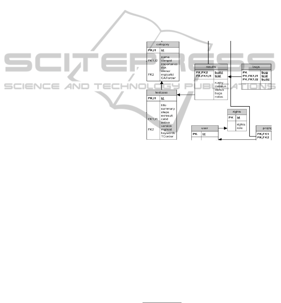
Testlink provides an API that enables the
manipulation of data via typical database operations
such as insert, delete and update. Figure 4 illustrates
part of the Testlink database, where we can see the
testcase table, its attributes and some of its relations
with other tables of the model. For example, each
test case must be related to a category and execution
result instances must always be associated with a
testcase.
Testlink also supports the Filter Module
functions because it can select test cases to compose
test suites, according to pre-defined keywords
associated with each test case during its edition.
The third Testlink function is to support the
Results Module functions. To that end, Testlink
saves all the results information, of past and current
execution, in a database that represents the Historic
Database in our architecture. This enables the
creation of several types of reports related to the
own test execution and statistical metrics generation.
In fact, Testlink already brings pre-defined
templates, which consolidate the historic test
information contained in its database. Another
resource is the query metrics report frame. Using
such resource, testers are able to perform some
simple queries on the test data results, which are
maintained in the database.
Figure 4: Part of the Testlink database structure.
We have generated some reports using Testlink
and observed that its reports are a bit limited. For
example, its query metrics report frame does not
enable complex queries using logic operators (and,
or, not, etc.). Thus, we are investigating, at the
moment, some report generator tools. Some
examples are Jasper Report
5
and Eclipse Birt
6
tools.
Our initial analysis shows that both tools offer an
appropriate level of flexibility and are a good
alternative if more complex reports are required.
Furthermore, they are also open source projects
under the GNU General Public License.
Testlink also supports the activities of planning
test sequences and its test execution. However, this
support is limited if we consider the premise of
automation. The selection of tests to compose a test
suite (a plan) is manually performed by testers and
they must manage details such as correct sequence,
constraints of time and opportunities for
optimization. Regarding the execution, Testlink is
5
http://community.jaspersoft.com/
6
https://www.eclipse.org/birt/
ICSOFT-EA2014-9thInternationalConferenceonSoftwareEngineeringandApplications
272

only an input interface where testers use the test
results to fit the interface fields. Thus, both modules
should be extended to support the premise of
automation.
4.2 Expanding the Planning Module
Testlink considers the concept of test plan as a table
in its database, so that each plan is a register in this
table. Test plans are then loaded by the execution
interface so that testers can choose one and execute
it. Considering the idea of automation, test plans
could be built via an external component and saved
in the Testlink database. To implement this idea, we
have specified the Planning Module as an Intelligent
Planning system (Ghallab et al, 2014), which
implements a schedule of test cases as a constraint
satisfaction problem (CSP). In this case, time,
resources and priorities are constraints that must be
respected during the development of a test plan.
The <I-N-C-A> (Issues - Nodes - Constraints -
Annotations) general-purpose ontology (Tate, 2003)
is used to represent plans. In <I-N-C-A>, each test
plan is considered to be made up of a set of Nodes,
which represent test cases of our domain. Nodes are
related by a set of detailed Constraints of diverse
kinds such as domain-state constraints. For example,
considering handset-inbox a plan variable, we can
have a constraint specifying that this variable must
be empty to the performance of a specific test case.
Annotations, in this specification, add
complementary human-centric and rationale
information to constraints, and can be seen as notes
on them.
The next step is to use the abstract constraint
representation to define required types of constraints
that represent features of the test plan. According to
<I-N-C-A>, a constraint is characterised by a type
(e.g., temporal), a relation (e.g., condition or effect)
and a sender-id attribute to indicate its source. The
constraint content is described as a list of
parameters, whose syntax depends on the type of the
constraint. For example, a domain-state constraint
has as parameter a list of PATTERN-
ASSIGNMENT, which is defined as a pair pattern-
value such as ((feature TC-id),value). An example is
((handset-inbox SMS-TC001),0) that means: the
amount of messages inside the handset inbox must
be zero to carry out the test case 001 from the SMS
suite.
Regarding temporal constraints, they must be
based on an explicit timeline approach, which
indicates that each test (node) has associated a
constraint I, expressing its interval, with initial (I
i
)
and final (I
f
) moments. Such a constraint could be
defined as shown in Figure 5, where the relation
attribute is set as interval. For this type of constraint,
we are composing the pattern, in the PATTERN-
ASSIGNMENT element, by the node identifier;
while the value is composed of the tuple (I
i
, I
f
).
Based on this definition, instances of pattern-
assignment for temporal constraints could be
represented as: (BW_TC012,(15,25)). This example
indicates that the test BW_TC012 must start at time
15 and spend 10 time units to be finished.
CONSTRAINT ::=
constraint type=“temporal” relation=“interval” sender-id=“ID”
parameterslist
PATTERN- ASSIGNMENT
/list/parameters
annotationsMAP MAP-ENTRY /map/annotations
/constraint
Figure 5: Temporal Constraint Definition.
The duration of a test can directly be defined as
the difference between the final and initial moments.
Consider now that we want to set temporal relations
between two tests t
1
and t
2
, with respective intervals
I(t
1
) and I(t
2
). The representation of temporal
relations via <I-N-C-A> follows the structure shown
in Figure 5, however with the relation attribute
specifying a temporal relation (before, equals, meets,
etc.) and a simple tuple (t
1
, t
2
) as parameter rather
than a PATTERN-ASSIGNMENT element. The
symbols a
1
and a
2
are the identifiers of the nodes
(tests) that are being related. Then, using the
notation “relation-attribute(parameter)” to represent
examples of temporal constraints, we could have:
before(test
1
,testy
2
) that means test
1
before test
2
.
We can employ the same idea to specify
resource and priority constraints. Resource
constraints specify which capability a test requires to
be performed. In this way, its constraint
specification follows the same structure of the
domain-state specification. This means, it is defined
as a pair pattern-value such as ((feature TC-id),
value). An example is ((testers BT_TC041),1) that
means: the amount of testers required to perform the
test case 41, from BT category, is one.
The priority constraint has a priority level as
relation attribute, which qualitatively indicates the
test priority from the set of five discrete values: Very
high, High, Medium, Low and Very low. In this
case, the parameter element only indicates the test
identifier. The semantic for priority can be
understood via temporal relations. For example,
consider that we have three tests to be executed: t
1
,
t
2
, and t
3
. If t
1
is classified as High priority, t
2
as
IntegrationofAutonomicMechanismstoaTestManagementSolution
273

Medium priority and t
3
as Very low priority; then we
can write down the following temporal relations:
before(test
1
,testy
2
), before(test
1
,testy
3
) and
before(test
2
,testy
3
). Thus, we can conclude that the
constraint type priority is just a more convenient
way to abstract several temporal relations among test
cases from our domain.
The interaction between Testlink and planning
module is performed via the Testlink Java API
client. Using such component, the planning module
can access the valid test cases in the Testlink
database and save valid test plans. At the moment,
the Priority Modifier (Figure 2) changes the priority
of test execution according to the frequency of errors
of each test case. This information is acquired via
queries in the database since the results of all tests
are saved in such tables.
4.3 Expanding the Execution Module
We are proving a level of intelligence to the
execution module via the use of a cognitive function.
To that end we have specified a knowledge base and
a reasoning process using JEOPS (Java Embedded
Object Production System) (Filho and Ramalho,
2000), a Java API that adds forward chaining, first-
order production rules to Java through a set of
classes designed to provide this language with some
kind of declarative programming. The knowledge
base is able to keep an internal representation of test
engineers’ expertise and use such knowledge to take
decisions and make choices during the test process.
Thus, we can implement autonomic actions in case
of failure, or as a way to improve the process when
some optimization opportunity is detected.
The creation of a knowledge base requires that
relevant data and information can be translated into
knowledge. Knowledge Engineering (Schreiber et al,
1999) is an artificial intelligence technique that
addresses such problem. This technique makes use
of some formal representation, such as rules in First
Order Logic. In this sense, “real” knowledge of the
world needs to be syntactically and semantically
mapped into a series of conventions that makes it
possible to describe things and then store them on a
base of knowledge. The knowledge engineer
specifies what is true and the inference procedure
figures out how to turn the facts into a solution to the
problem. After the creation of knowledge, it is
perceived that the information can be manipulated in
a systematic way and be applied into different
situations by simply assessing the kind of knowledge
involved.
The execution module is in fact the component
that accounts for replacing human testers during
repetitive and stressful test activities. However, our
experience during the specification of this module
shows that its implementation is very complex once
human testers are used to deal with several types of
problems and situations during test sessions.
Furthermore, each test suite has particular features
that must be covered via specific procedures. Thus,
the process of knowledge engineering is very hard,
mainly when we are considering a set of more than
500 test cases. To avoid this complexity, each test
suite can have its particular knowledge base, which
could be loaded in accordance with the test suite that
is active. This could avoid the complexity of dealing
with several facts and, mainly, conflict among rules.
Note however, that we must have a central
knowledge base that is always employed. This base
maintains the rules and facts that are commons to
every test suite and it avoids duplication of the same
knowledge in different bases. This simplification in
fact improves the knowledge engineering process.
On the other hand, we need an additional control
component to switch between knowledge bases.
Depending on the test plan (sequence of tests to be
executed), this control can insert several delays
because tests of different suites can be mixed in the
test plan. In this case, it could be more efficient the
use of a unique knowledge base. This question is
still open in our project and we need to perform
more experiments to decide for the best approach.
5 LEARNED LESSONS
The advantages of using a test management solution
can be observed if we analyse some process
qualification parameters. First, we could maintain
the same requirements coverage using a test suite
that is smaller than the original. This was observed
because Testlink enables the coverage and tracing of
requirements, so that it stresses test cases that
perform evaluations of same parts of the software.
This redundancy is present because some test cases
require the execution of some operations that were
already evaluated. Our challenge now is to use this
information also as a kind of constraint in the
planning process. The idea is to optimise the
coverage and avoid as much redundancy as possible.
A second advantage is the support provided to
the creation and maintenance of several specialised
test suites, which can be applied into specific
scenarios depending on the requirements of the
development team. We have observed that this
creation directly affects the efficiency of the
ICSOFT-EA2014-9thInternationalConferenceonSoftwareEngineeringandApplications
274

planning module. If test cases are self-contained
(they perform its own pre-configuration and
necessary operations) then we will have a large
percentage of redundancy. In this case, the planner is
not able to find a test plan with a high number-
tests/redundancy rate, considering a fixed total time.
Differently, dependent and granular test cases are
more appropriate to be used by planners, which are
able to reach higher values to the number-
tests/redundancy rate. Unfortunately such test cases
may require the performance of other test cases that
are not part of the test scenario (test cases are sorted
out by the filtering module in accordance with the
current test scenario). Thus, there is no guarantee
that a complete test plan is going to be found.
Third, the quality of final reports is ensured by
pre-defined templates. We can also create new kind
of templates to relate test parameters. The quality of
such templates can be improved via the use of
external report generation tools. We are still
analysing this alternative, however the integration of
such tools to our architecture seems to be simple
because they just need to access the Testlink
database. The disadvantage is that we will have one
more component rather than an integrated solution.
Furthermore, using the own Testlink, all the
generated reports could be accessed in real-time via
Web.
Fourth, the solution improves the efficiency of
the process, mainly in terms of execution time, due
to the level of automation provided by its modules.
For example, automation has avoided several
common errors related to human manipulation. In
fact, tests related to the evaluation of applications
are very repetitive and stressing due to the amount of
required keyboard inputs, navigation and
configurations. Finally, the maintenance of historic
data is very important to the measurement and
analysis of the quality of our test process. We intend
to use such data to support the continuous
improvement of our process via the DMAIC
technique (Wang, 2008).
The main problem of this approach is to codify
all the expertise of test engineers via facts and rules
to compose the knowledge base. This process is
called knowledge engineering and we are following
the KADS method presented in (Wielinga et al,
1992). Furthermore, a significant number of tests
tend to still be performed in a manual way, mainly
because they need some kind of mechanical
interaction (e.g., hard reset, press-and-hold
operations, etc.) during the test process.
A final remark is related to the interface between
the production environment and execution module.
This interface enables the exchange of information
about planned test suite, control messages and result
data. Note that this protocol must be standardized
otherwise new production environments will find
problems to be integrated to the architecture. An
option is to use or define a test ontology that covers
all required test information. This study is an
important research direction of this work, mainly
because it will enable the use of this architecture in
different software domains.
6 RELATED WORK
Several works in the current testing research aim at
improving the degree of automation (Polo et al,
2013). However they are focused on specific parts of
the test process, rather than the test environment as a
whole. In order, the idea of a powerful integrated
test environment which could automatically take
care of all test activities (generating the most
suitable test cases, executing them and issuing a test
report) is still a dream (Bertolino, 2007), although it
use to attract several followers. One interesting
example is the early DARPA sponsored initiative for
Perpetual Test and more recently in Saff and Ernst’
Continuous Testing approach (Saff and Ernst, 2004).
The main idea is to run tests in background on the
developers’ machines while they program. This
approach for test environment deals with several
issues regarding the online test creation, so that it is
a quite different from other approaches.
Another example that tries to push test
automation further, rather than focusing on specific
parts of the process, can be found in the Directed
Automated Random Testing (DART) approach
(Frantzen et al., 2006). This approach fully
automates unit testing by automated interface
extraction by static source-code analysis; automated
generation of a random test driver for this interface;
and dynamic analysis of program behaviour during
execution of the random test cases, aimed at
automatically generating new test inputs that can
direct the execution along alternative program paths.
Note that this approach is very directed to coverage,
while we are more worried about time optimization.
The Agitator commercial tool (Boshernitsan et
al, 2006) combines different analyses, such as
symbolic execution, constraint solving and directed
random input generation for generating input. This
approach has similar aims to DART, once it focuses
on test coverage. Any solution for test time
optimization is given during the creation of test
execution sequences. Microsoft Parameterized Unit
IntegrationofAutonomicMechanismstoaTestManagementSolution
275

Tests (PUT) (Tillmann and Schulte, 2006) is another
project whose focus is on coverage. It is very similar
to the Agitator tool, once it is also based on
symbolic execution techniques and constraint
solving to acquire a high coverage.
As general conclusion, we could assert that the
state of the art is very poor in researches that try to
establish a complete automated test environment. In
fact, the own definition of complete automated test
environment is an open-question. A possible reason
for that scenario is the fragmentation of software
testing researchers into several disjoint communities
(Bertolino, 2007), which have their isolated goals
and directions. Thus, investigations about integration
architectures, which could associate several isolated
automated test practices, may accelerate the
definition of such “utopian” environments.
7 CONCLUSION
This paper has discussed our experience in adapting
and using a test management solution, which was
based on the open source Testlink tool. Our focus
was on extending this tool with capabilities of
automation, intelligent control and use of statistic
metrics. To that end, we have specified a modular
test architecture and performed some experiments
using a subset or such architecture. The main
simplifications were: we do not use the TC
generation and mapping modules, the planning
module only managers priority and temporal
constraints, historical statistic metrics are only used
to find tests with high priority of failure, the result
module uses the own Testlink features and the
execution module was not totally configured, so that
several situations are not covered by the knowledge
base. Such situations are mainly related to failure
recovery procedures and they are the principal
targets for future researches.
ACKNOWLEDGEMENTS
This work was supported by the National Institute of
Science and Technology for Software Engineering
(INES – www.ines.org.br), funded by CNPq, grants
573964/2008-4.
REFERENCES
Aljahdali, S., Hussain, S., Hundewale, N., Poyil, A., 2012,
Test Management and Control, Proceedings of the 3rd
IEEE International Conference on Software Enginee-
ring and Service, pp.429,432, doi: 10.1109 /ICSESS.
2012.6269496.
Bertolino, A. 2007. Software Testing Research:
Achievements, Challenges, Dreams, Future of
Software Engineering, pp. 85-103.
Boshernitsan, M., Doong, R. and Savoia, A. 2006. From
Daikon to Agitator: lessons and challenges in building
a commercial tool for developer testing. In Proc.
ACM/SIGSOFT International Symposium on Software
Testing and Analysis, pp. 169–180.
Chin, L., Worth, D., Greenough, C. 2007. A Survey of
Software Testing Tools for Computational Science,
RAL Technical Reports, RAL-TR-2007-010.
Filho, C., Ramalho, G. 2000. JEOPS - The Java
Embedded Object Production System, Lecture Notes
In Computer Science, Vol. 1952, pp. 53 - 62, Springer-
Verlag, London, UK.
Frantzen, L., Tretmans, J. and Willemse, T. 2006. A
symbolic framework for model-based testing. In
Lecture Notes in Computer Science (LNCS) 4262, pp.
40–54. Springer-Verlag.
Ghallab, G., Nau, D., Traverso, P. 2004. Automated
Planning: theory and practice, Morgan Kaufmann
Publishers.
Lino, N., Siebra, C., Silva, F., Santos, A., 2008, An
Autonomic Computing Architecture for Network Tests
of Mobile Devices, Proceedings of the 7th
International Information and Telecommunication
Technologies Symposium, Foz do Iguaçu, Brazil.
Polo, M., Reales, P., Piattini, M., Ebert, C., 2013, Test
Automation, IEEE Software, 30(1):84- 89.
Prasanna, M., Sivanandam, S., Venkatesan, R.,
Sundarrajan, R. 2005. A Survey on Automatic Test
Case Generation, Academic Open Internet Journal, 15.
Saff, D. and Ernst, M. 2004. An experimental evaluation
of continuous testing during development. In Proc.
ACM/SIGSOFT International Symposium. on Software
Testing and Analysis, pp. 76–85.
Schreiber, G., Akkermans, H., Anjewierden, A., Hoog, R.,
Shadbolt, N., Velde, W., Wielinga, B., 1999,
Knowledge Engineering and Management: The
CommonKADS Methodology. The MIT Press.
Tate, A., 2003, <I-N-C-A>: an Ontology for Mixed-
Initiative Synthesis Tasks. Proceedings of the IJCAI
Workshop on Mixed-Initiative Intelligent Systems,
Acapulco, Mexico.
Tillmann, N. and Schulte, W. 2006. Unit tests reloaded:
Parameterized unit testing with symbolic execution.
IEEE Software, 23(4):38–47.
Wang, H. 2008. A Review of Six Sigma Approach:
Methodology, Implementation and Future Research,
4th International Conference on Wireless Communi-
cations, Networking and Mobile Computing, pp.1 – 4.
Wielinga, B., Schreiber, A. and Breuker, J. 1992. KADS:
a modelling approach to knowledge engineering,
Knowledge Acquisition Journal, 4(1): 5-53.
Yamaura, T., 1998, How to design practical test cases,
IEEE Software, 15(6):30-36.
ICSOFT-EA2014-9thInternationalConferenceonSoftwareEngineeringandApplications
276
