
Affine Invariant Shape Matching using Histogram of Radon Transform
and Angle Correlation Matrix
Makoto Hasegawa
1
and Salvatore Tabbone
2
1
Tokyo Denki University, 5 Senju Asahi-cho, Adachi-ku, Tokyo 120-8551 Japan
2
LORIA, UMR 7503, Universit
´
e de Lorraine, 54506 Vandoeuvre-l
`
es-Nancy, France
Keywords:
Shape Descriptor, Affine Invariance, Radon Transform, Dynamic Time Warping Distance, Beam Search.
Abstract:
An affine invariant shape matching descriptor using the histogram of Radon transform (HRT) and the dynamic
time warping (DTW) distance is proposed. Our descriptor based on the Radon transform is robust to shape
rotation, uniform scaling, and translation. For non-uniform scaling and shearing, our descriptor has a non-
linear sparse and dense distortion relative to the angle coordinates. Therefore, we apply DTW on a cost matrix
to be robust to these transformations. This cost matrix is defined as an angle correlation matrix based on the
product of two matrices only. Moreover, based on the beam search algorithm, we speed-up the time complexity
of our method. Experimental results show that our approach is fast to compute and competitive compared to
well-known descriptors.
1 INTRODUCTION
Geometric invariant shape descriptors are very impor-
tant for shape recognition. Usually shape descriptors
need to be invariant to classical geometric transfor-
mations like rotation, scaling and translation. How-
ever these transformations are not enough in several
applications. Recently, a shape recognition applica-
tion using a portable digital camera has been pro-
posed in (Liang et al., 2005) where shapes (included
in the photos) are deformed following affine distor-
tions. Therefore, it is necessary to be invariant to such
distortions.
RST invariant descriptors have been proposed for
shapes description and matching. Fourier transform
has been used as the starting point for the proposal of
many shape descriptors. The generic Fourier descrip-
tor (GFD) proposed by D. Zhang and G. Lu (Zhang
and Lu, 2002) is a typical one, and it is invariant to
rotation. However, in the case of translation and scal-
ing, GFD needs normalizations. The phase-only cor-
relation function (POC) proposed by C. Kuglin et al.
(D., 1975) has been shown to be effective for shape
matching. The Fourier–Mellin transform (FMT) pro-
posed by Chen et al. (Chen et al., 1994) is a typi-
cal Fourier descriptor invariant to RST transforma-
tions. Fourier descriptors have proved their robust-
ness to RST transformations and many applications
have been developed using these descriptors (Arafat
et al., 2009; Yuyama and Mitsuhashi, 2008; Ouyang
et al., 2006).
Many shape descriptors using the Radon trans-
form (Deans, 1993) have been defined in the liter-
ature by Tabbone et al. (Tabbone et al., 2006). A
method called the histogram of Radon transform
(HRT) (Tabbone et al., 2008) has been proposed us-
ing the Radon transform and a two-dimensional his-
togram. This descriptor encodes the shape length
at each orientation; it is invariant to the shape scal-
ing and translation, and the shape rotation is pro-
jected to a horizontal translation on the domain.
Recently, the Amplitude-only log Radon transform
(ALR) (Hasegawa and Tabbone, 2012) has been de-
fined. This descriptor is based on the Radon trans-
form, amplitude extraction, and log mapping. It is
invariant to shape translation; shape rotation and scal-
ing are projected into a two-dimensional translation.
To keep the invariance to these transformations (ro-
tation and scaling) the phase-only correlation func-
tion is used where the computation of several Fourier
transforms are needed. Combined with the DTW, this
descriptor is in addition invariant to any affine distor-
tions. The reported results on recognition rates are
very good compared to the literature but the complex-
ity of the approach is very high. A method proposed
by K.C. et al. (Santosh et al., 2011) combined the
Radon transform and the dynamic time warping. The
authors apply directly the dynamic time warping to
21
Hasegawa M. and Tabbone S..
Affine Invariant Shape Matching using Histogram of Radon Transform and Angle Correlation Matrix.
DOI: 10.5220/0004787000210029
In Proceedings of the 3rd International Conference on Pattern Recognition Applications and Methods (ICPRAM-2014), pages 21-29
ISBN: 978-989-758-018-5
Copyright
c
2014 SCITEPRESS (Science and Technology Publications, Lda.)

the radial coordinate in the Radon domain. The ap-
proach is invariant to the RST transformations also.
In the case of invariant methods to any affine distor-
tions, the local descriptor ASIFT was proposed by
Morel and Yu (Morel and Yu, 2009). ASIFT is an
enhanced method of the conventional SIFT proposed
by Lowe (Lowe, 2004). Shape matching is performed
following local features detected into the images.
In this paper, we focus on a novel shape match-
ing and descriptor method robust to classical RST
(Rotation Scaling Translation) transformations and
to distortions especially for non-uniform scaling and
shearing. We propose a new method based on
HRT (Tabbone et al., 2008) . When a shape has
any non-linear transformations as shearing or non-
uniform scaling, we show that such non-linear shape
transformations become an only horizontal sparse and
dense distortion relative to the angular coordinates in
the HRT domain. In order to obtain invariance to
such horizontal distortions, we apply the DTW which
is one of the famous method for non-linear match-
ing. Our method is robust to not only RST trans-
formations (rotation, scaling, and translation), but
also non-linear shape transformations. Furthermore,
a fast computation method with the beam search al-
gorithm (Tillmann et al., 1997) is performed in our
DTW. Our previous method with ALR-DTW descrip-
tor needs the phase-only correlation to generate the
angle correlation matrix. Our new method with HRT
can generate the angle correlation matrix by a matrix
product only, so we provide a very fast computation.
The remainder of this paper is organized as fol-
lows. The Radon transform and the HRT descriptor
are recalled in Sections 2 and 3. Our shape match-
ing methods – including the descriptor matching, the
dynamic time warping method, and the beam search
method are discussed in Section 4. Experimental re-
sults are given in Section 5, and finally our conclu-
sions are drawn in Section 6.
2 RADON TRANSFORM
We recall the Radon transform definition in this sec-
tion. Let a coordinate (x, y) in the two-dimensional
x − y plane described as x, and an original image rep-
resented as f (x). The Radon transform of f (x) is de-
fined as:
R
f
(θ, ρ) =
Z
f (x)δ(x · ξ − ρ)dx, (1)
where ξ = (cos θ, sinθ), and δ(·) is a delta function.
In other words, the Radon transform is the integral of
f (x) over lines
L
θρ
= {x ∈ R
2
|x · ξ = ρ}, (2)
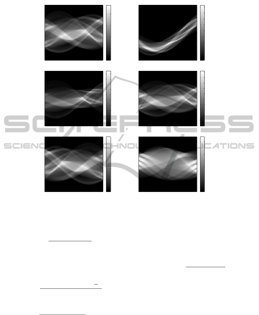
(a) (b) (c)
(d) (e) (f)
Figure 1: (a) Original image “Dog”. (b) RST transforma-
tion. (c) Shearing. (d) Non-uniform scaling. (e) Reflection.
(f) Original image “Hand”.
where ρ is the distance between the origin and L
θρ
, the
unit vector ξ and the angle θ describe the orientation
of the line L
θρ
. The line integral is computed by a
delta function δ(·).
The Radon transform has useful properties for the
RST transformations.
P1 Rotation : when shapes are rotated by θ
0
, the
Radon transform R
f
(θ, ρ) is translated to θ
0
rel-
ative to the coordinate θ as:
R
f
(θ, ρ) → R
f
(θ − θ
0
, ρ), (3)
where R
f
(θ, ρ) is cyclic for θ as:
R
f
(−θ, ρ) = R
f
(π − θ, ρ). (4)
P2 Scaling : when shapes are scaled by α, the Radon
transform R
f
(θ, ρ) is scaled by α relative to
the coordinate ρ. Moreover, the magnitude of
R
f
(θ, ρ) is multiplied by α as:
R
f
(θ, ρ) → αR
f
θ,
ρ
α
. (5)
P3 Translation : when shapes are translated to x
0
,
the Radon transform R
f
(θ, ρ) is translated to x
0
·ξ
relative to the coordinate ρ as:
R
f
(θ, ρ) → R
f
(θ, ρ − x
0
· ξ). (6)
The results of the Radon transform of Fig. 1 are
shown in Fig. 2.
3 HISTOGRAM OF RADON
TRANSFORM
3.1 Histogram
Let be f be a real function defined on a domain X :
f : X → Y . Besides, let us denote by # the cardinality
ICPRAM2014-InternationalConferenceonPatternRecognitionApplicationsandMethods
22
Angle
Radius
0 20 40 60 80 100 120 140 160
−150
−100
−50
0
50
100
150
0
50
100
150
200
(a)
Angle
Radius
0 20 40 60 80 100 120 140 160
−150
−100
−50
0
50
100
150
10
20
30
40
50
60
70
80
90
(b)
Angle
Radius
0 20 40 60 80 100 120 140 160
−150
−100
−50
0
50
100
150
20
40
60
80
100
120
140
160
180
200
(c)
Angle
Radius
0 20 40 60 80 100 120 140 160
−150
−100
−50
0
50
100
150
20
40
60
80
100
120
140
160
180
200
(d)
Angle
Radius
0 20 40 60 80 100 120 140 160
−150
−100
−50
0
50
100
150
0
50
100
150
200
(e)
Angle
Radius
0 20 40 60 80 100 120 140 160
−150
−100
−50
0
50
100
150
0
50
100
150
200
(f)
Figure 2: The Radon transform of Figs. 1(a) – 1(f).
of a set and by |X| the size (length) of a domain X.
Hence, the point-wise histogram of f is expressed by:
H ( f )(v) =
#{x ∈ X|v = f (x)}
|X|
. (7)
By the normalization using |X| in Eq. (7), the his-
togram H ( f )(v) means a generation probability of v.
Actually, the range of v is quantized by N bins v
i
(1 ≤ i ≤ N) and, we put the data f (x) into the bins:
H ( f )(v
i
) =
#{x ∈ X| | f (x) − v
i
| <
4
2
}
|X|
, (8)
where #{.} means the number of items in a bin, and:
4 =
max f (x) − min f (x)
N
. (9)
The number of bins N is usually set by experience.
3.2 HRT Descriptor
The HRT descriptor is defined as a matrix of frequen-
cies computed on the Radon transform for the angle
parameter (Tabbone et al., 2008). Thus, the HRT de-
scriptor represents a 2D histogram of shape lengths at
each orientation. More precisely, the HRT descriptor
D
f
is:
D
f
(θ, v) = H (R
f
(θ, ·))(v), (10)
with
R
f
(θ, ρ) →
R
f
(θ, ρ)
max
θ,ρ
(R
f
(θ, ρ))
, (11)
where θ ∈ [0, π); v > 0, and X in Eq. (7) is:
X
θ
=
ρ|R
f
(θ, ρ) > 0
(12)
so that the generation probability of histograms is in-
variant to the shape scaling.
The HRT descriptor has beneficial properties as:
P4 Rotation: when shapes are rotated by θ
0
, the HRT
descriptor is translated to θ
0
relative to the coor-
dinate θ as:
D
f
(θ, v) → D
f
(θ − θ
0
, v), (13)
where D(θ, v) is cyclic for the θ as:
D
f
(−θ, v) = D
f
(π − θ, v). (14)
AffineInvariantShapeMatchingusingHistogramofRadonTransformandAngleCorrelationMatrix
23
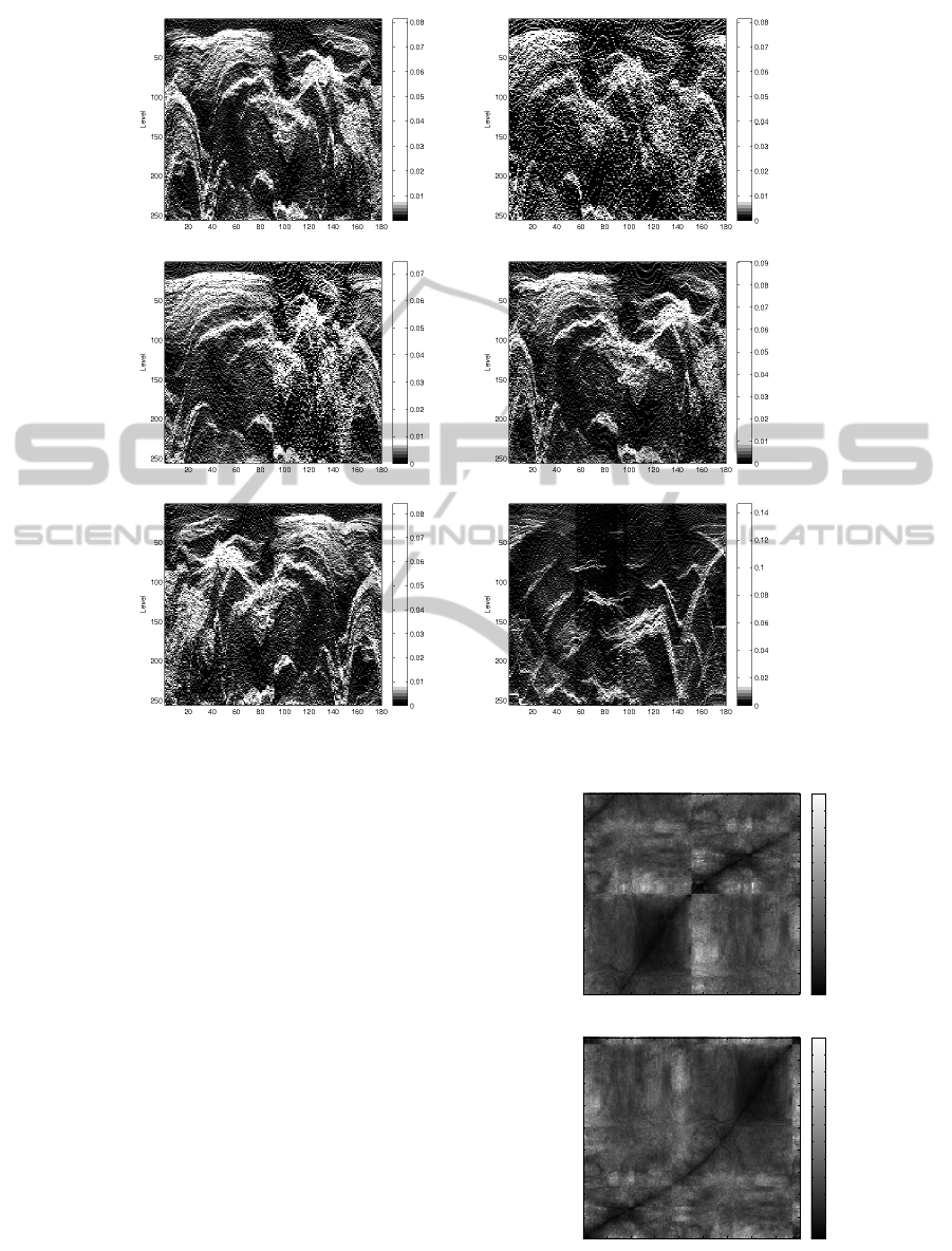
(a) (b)
(c) (d)
(e) (f)
Figure 3: Our HRT for Figs. 1(a) – 1(f).
P5 Scaling and Translation: when shapes are scaled
or translated, the HRT descriptor is invariant.
P6 Non-linear Distortion: when shapes get non-
linear distortions as shearing or non-uniform scal-
ing, the HRT descriptor gets sparse and dense dis-
tortion, only horizontally, on the transform do-
main.
Let’s consider for instance Fig. 1(c). This figure
is a slanted version (θ = 30
◦
) of Fig. 1(a). Following
the Radon transform, the integral of f (x) over verti-
cal lines (θ = 90
◦
) on Fig. 1(a) are equal to the case
of Fig. 1(c). On the other hand, the integral of f (x)
over horizontal lines (θ = 0
◦
) on Fig. 1(a) are dif-
ferent from the slant lines on Fig. 1(c). As a result,
some columns on the domain remain the same and
some columns are translated horizontally. This result
makes the horizontal sparse and dense distortion on
the domain. Therefore, in order to obtain invariance to
non-linear horizontal distortions, we apply the DTW
for the non-linear matching.
The HRT descriptors of the original shapes in
Query Angle
Template Angle
20 40 60 80 100 120 140 160 180
20
40
60
80
100
120
140
160
180
100
150
200
250
300
350
400
450
500
550
600
(a)
Query Angle
Template Angle
20 40 60 80 100 120 140 160 180
20
40
60
80
100
120
140
160
180
100
150
200
250
300
350
400
450
500
550
600
(b)
Figure 4: (a) The cost matrix for the HRT images shown in
Figs. 3(a) and 3(c). (b) The normalized warping path.
ICPRAM2014-InternationalConferenceonPatternRecognitionApplicationsandMethods
24

Figs. 1(a)–1(f) are shown in Fig. 3 (where the num-
ber of bins N = 256). In the case of the RST trans-
formations shown in Fig. 1(b), our descriptor shown
in Fig. 3(b) is only translated horizontally for the
shape rotation. Our descriptor is invariant to the shape
scaling and translation. In the case of shearing and
non-uniform scaling as shown in Figs. 1(c) and 1(d),
our descriptor (see Figs. 3(c) and 3(d)) has horizontal
sparse and dense distortions. In the case of reflection
shown in Fig. 1(e), our descriptor (see Fig. 3(e)) is re-
flected in the angle coordinate. For a different shape
shown in Fig. 1(f), our descriptor in Fig. 3(f) is differ-
ent from Fig. 3(a).
4 SHAPE MATCHING
4.1 Angle Correlation Matrix
Since our descriptor is computed with discrete values,
it can be described using a matrix as:
D
f
(θ, v) → D
θ,v
, (15)
where θ is digitized with integers 1 ∼ 180, and v is the
bin number. Therefore, the size of D
θ,v
is 180 × N.
Two descriptors one for the query and the other for
the template are denoted as Q
θ,v
and T
θ,v
.
Our angle correlation matrix M
i, j
is computed as:
M
i, j
= Q
T
j,v
× T
i,v
, (16)
where i and j are respectively the template and the
query angle; the size of M
i, j
is 180 × 180. Q
T
means
a transposition of a matrix Q. A cost matrix C
i, j
is
computed using the angle correlation matrix M
i, j
as:
C
i, j
=
1
M
i, j
. (17)
A cost matrix C
i, j
is shown in Fig. 4(a). A val-
ley line (in black in the figure) called “warping path”
appears in C
i, j
, when the two shapes are same even
if they have RST transformations or any affine distor-
tions.
The warping path is denoted as:
P = p
1
, p
2
, ·· · , p
k
, ·· · , p
K
, (18)
where p
k
is a coordinate (i
k
, j
k
) on C
i, j
, p
1
= (1, 1),
p
K
= (180, 180), and 180 ≤ K < 360. We normalize
C
i, j
periodically so that the position with the mini-
mum value in C
i, j
becomes (1, 1). If the minimum
value in C
i, j
is not unique, the minimum value on the
most upper-left on the image is chosen. Fig. 4(b) is
the result of the normalized warping path.
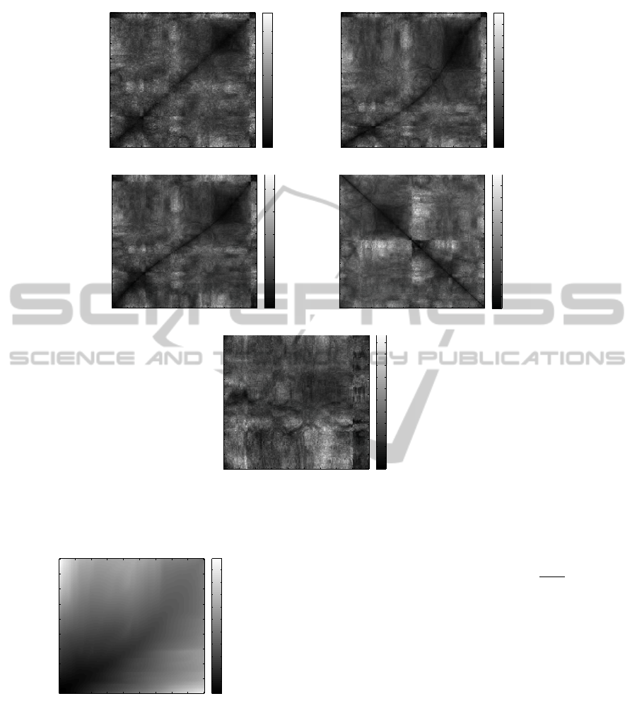
Cost matrices shown in Figs. 5(a) – 5(e) are cases
using the query shown in Fig. 3(a) and templates
shown in Figs. 3(b) – 3(f), respectively. For only RST
transformations (see Fig. 5(a)), a straight valley line
appears in the domain. In the case of shearing and
non-uniform scaling shown in Figs. 5(b) and 5(c), a
curved valley line appears in each case. A cost matrix
for shapes which are different as shown in Fig. 5(e)
has no valley line.
In the case of the shape reflection, the Radon im-
age and HRT image are reflected following the angu-
lar coordinate as shown in Figs. 2(e) and 3(e). Since
the corresponding angle order is reversed, the cost
matrix C
i, j
is set as: C
i, j
← C
i,181− j
. In this case, the
cost matrix show (see Fig. 5(d)) a straight valley line
with negative slope due to the reflection property of
the Radon transform.
4.2 Dynamic Time Warping (DTW)
Our dynamic time warping is performed using an ac-
cumulated cost matrix A
i, j
to search the minimum
cost as:
A
i, j
= C
i, j
+ min
(m,n)
A
m,n
(m, n) ∈
{
(i − 1, j),(i, j − 1), (i − 1, j − 1)
}
, (19)
where A
1, j
= C
1, j
+ A
1, j−1
; A
i,1
= C
i,1
+ A
i−1,1
;
A
1,1
= C
1,1
. Therefore, Eq. (19) tracks the warping
path. An accumulated cost matrix A
i, j
is shown in
Fig. 6.
We track back the warping path p
k
= (i
k
, j
k
) from
p
K
= (180, 180) to p
0
= (1, 1) as:
p
k−1
= arg min
(m,n)
A
m,n
(m, n) ∈
{
(i
k
− 1, j
k
), (i
k
, j
k
− 1), (i
k
− 1, j
k
− 1)
}
.
(20)
The matching score between two shapes is com-
puted using the path length K as:
S =
K
A
180,180
. (21)
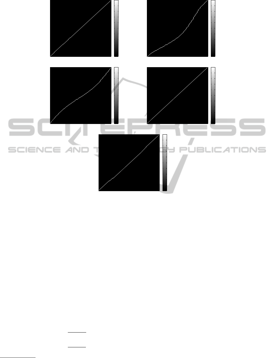
Warping paths shown in Figs. 7(a) – 7(e) are the
case using a query shown in Fig. 3(a) and templates
shown in Figs. 3(b) – 3(f), respectively. A warping
path under the RST transformations shown in Fig.
7(a) is a straight line. In the case of shearing and non-
uniform scaling shown in Figs. 7(b) and 7(c), their
warping paths are curved lines. In the case of re-
flection and matching with different shapes (see Figs.
7(d) and 7(e)), their corresponding warping paths are
also straight lines.
AffineInvariantShapeMatchingusingHistogramofRadonTransformandAngleCorrelationMatrix
25
Query Angle
Template Angle
20 40 60 80 100 120 140 160 180
20
40
60
80
100
120
140
160
180
100
200
300
400
500
600
(a)
Query Angle
Template Angle
20 40 60 80 100 120 140 160 180
20
40
60
80
100
120
140
160
180
100
150
200
250
300
350
400
450
500
550
600
(b)
Query Angle
Template Angle
20 40 60 80 100 120 140 160 180
20
40
60
80
100
120
140
160
180
100
200
300
400
500
600
(c)
Query Angle
Template Angle
20 40 60 80 100 120 140 160 180
20
40
60
80
100
120
140
160
180
100
150
200
250
300
350
400
450
500
550
(d)
Query Angle
Template Angle
20 40 60 80 100 120 140 160 180
20
40
60
80
100
120
140
160
180
150
200
250
300
350
400
450
500
550
600
650
(e)
Figure 5: Cost matrices: (a) – (e) are the cases with a query shown in Fig. 3(a) and templates shown in Figs. 3(b) – 3(f),
respectively.
Query Angle
Template Angle
20 40 60 80 100 120 140 160 180
20
40
60
80
100
120
140
160
180
0.5
1
1.5
2
2.5
3
3.5
4
4.5
5
x 10
4
Figure 6: The accumulated cost matrix of Fig. 4(b).
4.3 Beam Search
The beam search(Tillmann et al., 1997) is a
fast computation algorithm for the DTW. Our
beam search skips A
i, j
computation in Eq.
(19), when A
i−1, j
> T
i−1, j
, A
i, j−1
> T
i, j−1
, and
A
i−1, j−1
> T
i−1, j−1
(A
i, j
is initialized to ∞ at the
first), where:
T
i, j
= T
min
+ (T
max
− T
min
) ×
i + j
360
. (22)
T
min
and T
max
are thresholds for the beam band. It
means a pruning searching tree defined by Eq. (19).
An accumulated cost matrix without the beam
search is shown in Fig. 8(a). Its warping paths is
denoted using a black line. The result of the beam
search, an accumulated cost matrix within thresholds
T
min
= 1000 and T
max
= 30000 is shown in Fig. 8(b).
A search band is generated, and the computation for
the accumulated cost matrix is reduced. We can re-
mark that the warping path is included in the search
band.
5 EXPERIMENTAL RESULTS
To demonstrate the performance of our descriptor,
we have carried out experiments based on commonly
used binary datasets. An affine distorted shape dataset
ICPRAM2014-InternationalConferenceonPatternRecognitionApplicationsandMethods
26
Query Angle
Template Angle
20 40 60 80 100 120 140 160 180
20
40
60
80
100
120
140
160
180
0
0.1
0.2
0.3
0.4
0.5
0.6
0.7
0.8
0.9
1
(a)
Query Angle
Template Angle
20 40 60 80 100 120 140 160 180
20
40
60
80
100
120
140
160
180
0
0.1
0.2
0.3
0.4
0.5
0.6
0.7
0.8
0.9
1
(b)
Query Angle
Template Angle
20 40 60 80 100 120 140 160 180
20
40
60
80
100
120
140
160
180
0
0.1
0.2
0.3
0.4
0.5
0.6
0.7
0.8
0.9
1
(c)
Query Angle
Template Angle
20 40 60 80 100 120 140 160 180
20
40
60
80
100
120
140
160
180
0
0.1
0.2
0.3
0.4
0.5
0.6
0.7
0.8
0.9
1
(d)
Query Angle
Template Angle
20 40 60 80 100 120 140 160 180
20
40
60
80
100
120
140
160
180
0
0.1
0.2
0.3
0.4
0.5
0.6
0.7
0.8
0.9
1
(e)
Figure 7: Warping paths: (a) – (e) are the cases with a query shown in Fig. 3(a) and templates shown in Figs. 3(b) – 3(f),
respectively.
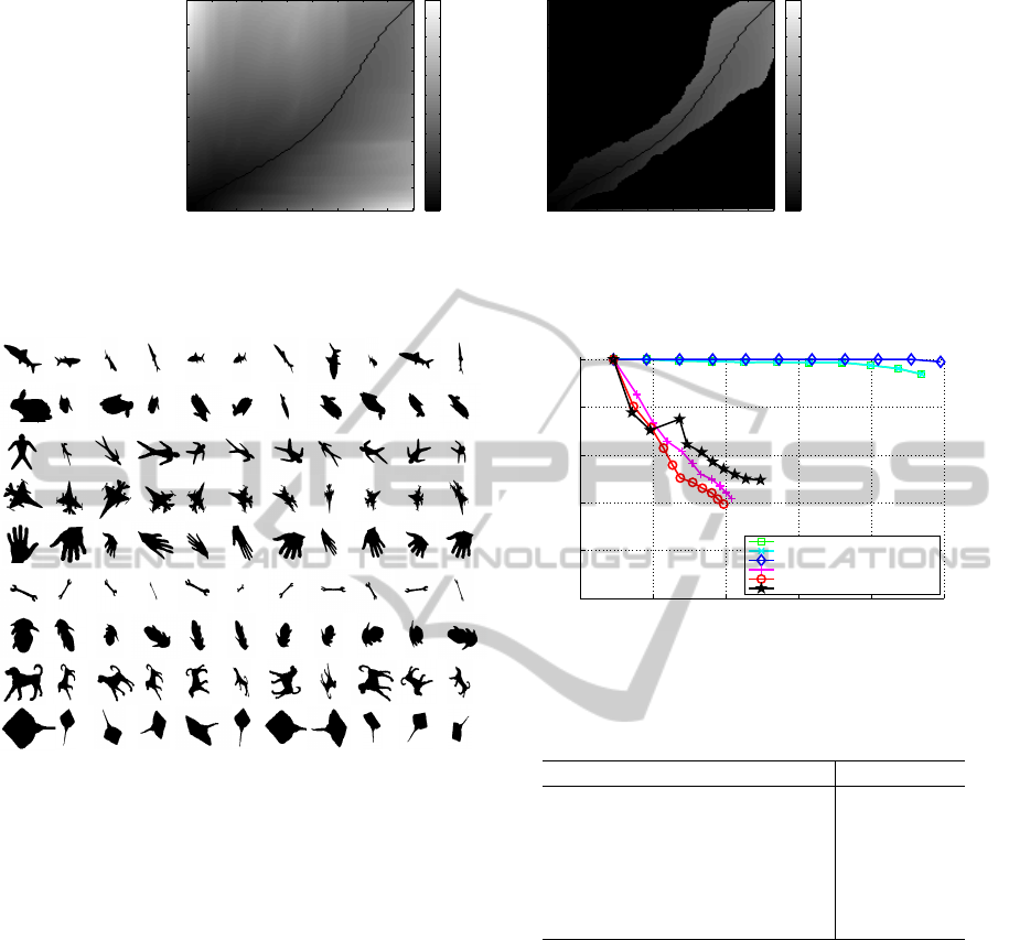
shown in Fig. 9 consists of 9 categories with affine
distortions (99 images). These datasets are created
from a commonly used dataset in many works and is
available from the research community
1
.
Our method (HRT-DTW) is computed with and
without the beam search algorithm; ALR with the
dynamic time warping (ALR-DTW) (Hasegawa and
Tabbone, 2012), HRT (Tabbone et al., 2008), FMT
(Chen et al., 1994), and ASIFT (Morel and Yu, 2009).
In the case of ASIFT, we use an source code provided
by Morel and Yu on their web site
2
.
The performance is evaluated using the precision-
recall measure (Davis and Goadrich, 2006) defined
as:
Precision =
t p
t p + f p
Recall =
t p
t p + f n
, (23)
1
http://www.lems.brown.edu/vision/researchAreas/SIID/
2
http://www.cmap.polytechnique.fr/ yu/
where the true positives t p is the number of items
correctly labeled as belonging to the positive class,
the false positives f p is the number of items incor-
rectly labeled as belonging to the class, and the false
negatives f n is the number of items which were not
labeled as belonging to the positive class but should
have been. Namely, the precision is the number of
true positives divided by the total number of elements
labeled as belonging to the positive class. The recall is
the number of true positive divided by the total num-
ber of elements that actually belong to the positive
class. We create a precision-recall curve by plotting
Precision and Recall at each retrieval rate.
Precision-recall curves of each method is shown
in Fig. 10. Our method and ALR-DTW are very simi-
lar and have very high performances compared to the
other. Both descriptors are robust to any affine distor-
tions. Moreover, we can remark no decrease with the
beam search algorithm.
The processing time to match two images for dif-
ferent methods is shown in Table 1 using Intel Core
AffineInvariantShapeMatchingusingHistogramofRadonTransformandAngleCorrelationMatrix
27
Query Angle
Template Angle
20 40 60 80 100 120 140 160 180
20
40
60
80
100
120
140
160
180
0
0.5
1
1.5
2
2.5
3
3.5
4
4.5
5
x 10
4
(a)
Query Angle
Template Angle
20 40 60 80 100 120 140 160 180
20
40
60
80
100
120
140
160
180
0
0.5
1
1.5
2
2.5
3
3.5
4
4.5
5
x 10
4
(b)
Figure 8: (a) The accumulated cost matrix; (b) the result of the beam search with the thresholds T
min
= 1000 and T
max
= 30000.
The warping paths are denoted with black lines.
Figure 9: An affine distorted dataset. This dataset has 9
categories with affine distortions.
i7-366U 2.00 GHz CPU. ASIFT is implemented in C,
and the other methods are implemented using MAT-
LAB. HRT and FMT are very fast, however they are
not robust to any affine distortions. Comparing with
ALR-DTW, our processing time is about one tenth
compared to ALR-DTW. It is observed that the com-
puting of the angle correlation matrix by a matrix
product in Eq. (16) provides very fast computation
and the processing time using our beam search algo-
rithm is significant (about one half less time compared
to HRT-DTW).
6 CONCLUSIONS
We propose a new method based on the HRT descrip-
tor. The HRT descriptor is robust to shape scaling,
translation and rotation. However, for non-uniform
shape scaling and shearing, this descriptor has a non-
linear sparse and dense distortions relative to the an-
0 0.2 0.4 0.6 0.8 1
0
0.2
0.4
0.6
0.8
1
Recall
Precision
HRT-DTW
HRT-DTW with beam search
ALR-DTW
HRT
FMT
ASIFT
Figure 10: Precision-recall curves of each method.
Table 1: Processing time for the matching between two im-
ages.
Method Time [Sec.]
HRT-DTW 0.43
HRT-DTW(with beam search) 0.27
ALR-DTW 4.03
HRT 0.01
FMT 0.01
ASIFT 11.97
gle coordinates. Therefore, we propose a novel affine
invariant shape matching combining HRT with the
DTW. DTW is set on a cost matrix defined as an angle
correlation matrix based on the product of two matri-
ces only. The computational complexity is reduced
using the beam search algorithm. Reported results on
a common dataset have shown a very good robust-
ness to any affine transformations with low complex-
ity time thanks to the angle correlation matrix product
and the beam search algorithm.
In order to keep our approach scalable, future
works will be devoted to optimize the value of the pa-
rameters related to the size of the histogram (number
of bins) and the Radon transform (number of orienta-
tions).
ICPRAM2014-InternationalConferenceonPatternRecognitionApplicationsandMethods
28

REFERENCES
Arafat, S. Y., Saleem, M., and Hussain, S. A. (2009). Com-
parative analysis of invariant schemes for logo classi-
fication. International Conference on Emerging Tech-
nologies, pages 256–261.
Chen, Q.-S., Defrise, M., and Deconinck, F. (1994). Sym-
metric phase-only matched filtering of Fourier-Mellin
transforms for image registration and recognition.
IEEE Trans. Pattern Anal. Mach. Intell., 16(12):1156–
1168.
D., K. C. (1975). The phase correlation image alignment
methed. Proc. Int. Conference Cybernetics Society,
pages 163–165.
Davis, J. and Goadrich, M. (2006). The relationship be-
tween precision-recall and roc curves. In Proceed-
ings of the 23rd international conference on Machine
learning, ICML ’06, pages 233–240, New York, NY,
USA. ACM.
Deans, S. R. (1993). The Radon Transform and Some of Its
Applications. Krieger Publishing Company.
Hasegawa, M. and Tabbone, S. (2012). Affine invariant
shape matching using Radon transform and dynamic
time warping distance. In ACM Symposium On Ap-
plied Computing (ACM SAC), Trento.
Liang, J., Doermann, D., and Li, H. (2005). Camera–based
analysis of text and documents: a survey. Interna-
tional Journal on Document Analysis and Recogni-
tion, 7(2 – 3):83 – 104.
Lowe, D. G. (2004). Distinctive image features from scale-
invariant keypoints. International Journal of Com-
puter Vision, 60(2):91–110.
Morel, J.-M. and Yu, G. (2009). ASIFT: A new framework
for fully affine invariant image comparison. SIAM J.
Imaging Sciences, 2(2):438–469.
Ouyang, Z., Feng, J., Su, F., and Cai, A. (2006). Fingerprint
matching with rotation-descriptor texture features. In
ICPR (4), pages 417–420. IEEE Computer Society.
Santosh, K. C., Lamiroy, B., and Wendling, L. (2011).
DTW for matching Radon features: A pattern recogni-
tion and retrieval method. In ACIVS, pages 249–260.
Tabbone, S., Terrades, O. R., and Barrat, S. (2008). His-
togram of Radon transform. a useful descriptor for
shape retrieval. In ICPR, pages 1–4. IEEE.
Tabbone, S., Wendling, L., and Salmon, J.-P. (2006). A
new shape descriptor defined on the Radon trans-
form. Computer Vision and Image Understanding,
102(1):42–51.
Tillmann, C., Vogel, S., Ney, H., Zubiaga, A., and Sawaf,
H. (1997). Accelerated dp based search for statisti-
cal translation. In Kokkinakis, G., Fakotakis, N., and
Dermatas, E., editors, EUROSPEECH. ISCA.
Yuyama, J. and Mitsuhashi, W. (2008). Shape invariant
recognition of polygonal road signs by deforming ref-
erence templates. ICSPCS, pages 1–6.
Zhang, D. and Lu, G. (2002). Shape-based image retrieval
using generic Fourier descriptor. Sig. Proc.: Image
Comm., 17(10):825–848.
AffineInvariantShapeMatchingusingHistogramofRadonTransformandAngleCorrelationMatrix
29
