
Study of Interference Noise in Multi-Kinect Set-up
Tanwi Mallick, Partha Pratim Das and Arun Kumar Majumdar
Department of Computer Science and Engineering, Indian Institute of Technology, Kharagpur, India
Keywords:
Image Formation and Preprocessing, Device Characterization and Modelling, Multi-Kinect Models of Image
Formation, IR Interference Noise.
Abstract:
Kinect
TM
, a low-cost multimedia sensing device, has revolutionized human computer interaction (HCI) by
making various applications of human activity tracking affordable and widely available. Often multiple
Kinects are used in imaging applications to improve the field of view, depth of field and uni-directional vision
of a single Kinect. Unfortunately, multiple Kinects lead to IR Interference Noise (IR Noise, in short) in the
depth map. In this paper we analyse the estimators for interference noise, survey various imaging techniques
to mitigate the interference at source, and characterize them in parallel to a well-known classification system
in telecom industry. Finally we compare their performance from reported literature and outline our on-going
research to control interference noise by software shuttering.
1 INTRODUCTION
Kinect
TM
is a motion sensing input device for the
Xbox 360 gaming console. It provides RGB, IR,
depth, skeleton, and audio streams to an application.
Beside being a gesture-controlled console for gaming,
Kinect offers inexpensive depth sensing for a wide
variety of emerging applications in computer vision,
augmented reality, robotics, and human-computer in-
teractions.
In spite of its versatility Kinect suffers from a
number of limitations. First, it has limited field of
view (43
◦
in vertical and 57
◦
in horizontal). A full
human figure is visible only when it is about 3m away
which is very close to the maximum depth range of
3.5m. Second, Kinect has only a uni-directional vi-
sion of objects or people. It needs to be moved around
to capture the opposite side. Finally, the IR speckles
cast depth shadows in the scene due to the occlusion
of one object by another or even just the background.
Two or more Kinects are used simultaneously to over-
come these limitations.
When more than one Kinects are used for a scene,
their IR patterns often overlap and interfere with each
other. This shows up as blind spots or holes (zero
depth) in the depth map in the overlapping area. In-
terfering IR also increases instability and results in vi-
brating depth values even for static points. These are
known as IR Interference Noise (IR Noise). Noise fil-
tering methods are used to reduce such defects. How-
ever, an alternate approach attempts to modify the
imaging technique itself to control the IR noise at
source.
In this paper we study its different aspects of IR
noise at length. First we analyse four estimators for
IR noise in Section 2. In Section 3, we review vari-
ous imaging techniques to control the noise at source.
We introduce a novel characterization of these tech-
niques in parallel to the classification of digital trans-
mission technologies. We also compare the perfor-
mance of the techniques. In Section 4, we describe
our on-going work with software shutters. Finally, we
conclude in Section 5.
2 ESTIMATORS FOR IR NOISE
We conduct experiments with two Kinects to analyse
IR noise. We present our results in Figure 1 and Ta-
ble 1. The noise is measured by keeping the Kinects
in two configurations:
• Parallel (180
◦
): The Kinects are placed (Fig-
ure 1(a)) side-by-side on the same line, are par-
allel to each other and face in the same direc-
tion. The depth images are shown in Figures 1(e)
and 1(h).
• Perpendicular (90
◦
): The Kinects are placed (Fig-
ure 1(b)) perpendicular to each other. The depth
image is shown in Figure 1(i).
173
Mallick T., Das P. and Majumdar A..
Study of Interference Noise in Multi-Kinect Set-up.
DOI: 10.5220/0004736401730178
In Proceedings of the 9th International Conference on Computer Vision Theory and Applications (VISAPP-2014), pages 173-178
ISBN: 978-989-758-003-1
Copyright
c
2014 SCITEPRESS (Science and Technology Publications, Lda.)
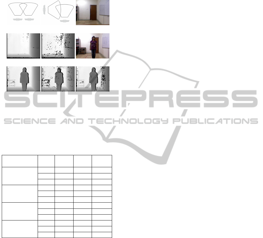
For comparison a room (Figures 1(c)– 1(d)) and a hu-
man figure (Figures 1(f)– 1(g)) are imaged. All scenes
are taken to be static.
(a) (b) (c)
(d) (e) (f)
(g) (h) (i)
Figure 1: Experiments for IR noise estimation. (a) Paral-
lal (180
◦
) Set-Up (b) Perpendicular (90
◦
) Set-Up (c) Room
(d) Single Kinect (e) Parallel (180
◦
) Kinects (f) Human (g)
Single Kinect (h) Parallel (180
◦
) Kinects (i) Perpendicular
(90
◦
) Kinects.
Table 1: Estimators for IR noise.
Noise Angle Scene Single Two
Measure (
◦
) Kinect Kinects
% ZD Error 180 Room 6.92% 10.93%
180 Human 4.01% 8.25%
90 Human 4.01% 7.40%
Avg 180 Room 329 639
(d
max
− d
min
) 180 Human 206 625
90 Human 206 408
Average 180 Room 89.15 185.71
Standard 180 Human 58.26 168.91
Deviation 90 Human 58.26 118.65
% Pixels with 180 Room 8.08% 17.52%
d
min
= 0 & 180 Human 5.32% 19.84%
d
max
> 0 90 Human 5.32% 11.87%
To get a quantitative idea of the interference noise
we compute four different measures of error in Ta-
ble 1 over 100 consecutive frames from the above
depth videos. % ZD Error counts the percentage of
pixels having zero depth. Next we find the range of
depth values (d
min
to d
max
) for all pixels. We use the
average of this range as the measure to directly es-
timate the instability. We compute the average stan-
dard deviation for the videos based on the standard
deviations of depth values at all pixels (excluding the
all-zero pixels). We also count the percentage of pix-
els that vary between ZD (zero-depth) and non-zero
depths. We observe that all four measures of instabil-
ity more than doubles when the IRs of two Kinects op-
erate simultaneously. Further, the noise is lower for
perpendicular configuration than the parallel one.
3 MITIGATION OF
INTERFERENCE AND
REDUCTION OF IR NOISE AT
SOURCE
Several imaging techniques have been devised to min-
imize the IR noise at source. Borrowing from the
classification of digital transmission technologies we
classify them as follows:
3.1 SDM IR Projections
The first, Space Division Multiplexed (SDM), ap-
proach places the Kinects with their views geometri-
cally separated. With this when the IRs have minimal
overlap their interference minimizes (Table 1). The
following works use SDM configurations under vari-
ous placement geometries.
Circular Placement
Caon et al. (Caon et al., 2011) present a system for
gestures interaction using multiple Kinects. They ex-
periment with 2 or 3 equidistant Kinects placed at
45
◦
and 90
◦
separation to minimize mutual interfer-
ence. Using % ZD Error as a measure they show that
2 Kinects at 90
◦
produce the least overlap and best
skeletal detection by OpenNI library.
In a similar set up Berger et al. (Berger et al.,
2011a) place 3 Kinects in a small half circle with
an angular spacing of 45
◦
between each to estimate
the turbulent flows of propane gas plume around var-
iously shaped objects. Each Kinect captures the di-
rectly facing plane where the plume refracts IR pat-
terns to provide distortion cues in the depth image. It
is shown that for flat and diffuse planes, the Kinects
do not produce any significant interference noise for
turbulence measurement.
Axial and Diagonal Placement
In (Ahmed, 2012) Naveed Ahmed presents a sys-
tem to acquire a 360
◦
view of human figures using
6 Kinects and performs 3D animation reconstruction.
Placing 6 Kinects at NE, East, SE, SW, West, and NW
directions author shows that their interference is min-
imal and the multi-view depth data is suitable for 3D
point-cloud reconstruction.
Maimone and Fuchs introduce a 3D tele-presence
system (Maimone and Fuchs, 2011) using an array
VISAPP2014-InternationalConferenceonComputerVisionTheoryandApplications
174

of 6 Kinects placed strategically to minimize inter-
ference. Further they use a 2-Pass Median Filter for
filling depth holes due to interference.
Vertical Placement
A 3-Kinect set-up is presented by Tong et al. (Tong
et al., 2012) for scanning full human figures in 3D. To
avoid interference two Kinects are used from one side
to cover the top and the bottom one-third of the body
while the third Kinect is used from the back for the
middle part.
Limitations of SDM: Physical separation helps
minimize interference; yet SDM suffers from the fol-
lowing drawbacks:
• SDM is not suitable for every application as only a
few multi-Kinect configurations offer clear avoid-
ance.
• Even with separation, Kinects do show enough IR
noise (Figure 1 and Table 1) and the data often
need noise cleaning.
3.2 TDM IR Projections
In the Time Division Multiplex (TDM) approach each
Kinect gets a well-defined time slot to project its own
pattern and capture the result with minimal interfer-
ence. The following shuttering TDM techniques are
common.
Mechanical Shutter (TDM-MS)
A Mechanical Shutter periodically blocks the IR of
each Kinect except for the time when the gap allows
the IR to project its pattern into the scene. By con-
trolling the speed and phase of the shutters, various
TDM schemes can be implemented. Pairs of flat shut-
ters controlled by a motor in synchronized fashion are
used in (Kramer et al., 2012) to block and uncover IR
emitter-camera pair for each Kinect in turn. (Berger
et al., 2011b; ?) use a fast revolving disk with a gap.
Only the IR emitter is blocked by this disk. Each
Kinect is mounted to such a disk rotating at the same
speed, but with a different phase, ensuring only one
IR can project at any given time. TDM-MS is the
most widely used TDM technique.
Electronic Shutter (TDM-ES)
An Electronic Shutter (Faion et al., 2012) is an in-
vasive hardware solution where the controller of the
IR emitter is periodically bypassed to stop the IR
emitter from generating the speckle patterns when
needed. This is deftly synchronized with the IR cam-
era to mark if the current frame is completely cap-
tured. TDM-ES is delicate and invasive but effective.
Software Shutter (TDM-SS)
Microsoft’s Kinect SDK v1.6 (Kinect Windows
Team, 2012) has introduced a new API
1
to control the
IR emitter as a Software Shutter. Earlier the IR emit-
ter was always active when the camera was active.
Using this API the IR emitter can be put off as needed.
This is the most effective TDM scheme. However, to
the best of authors’ knowledge, no multi-Kinect ap-
plication has yet been reported with TDM-SS. So we
are currently conducting a series of experiments (Sec-
tion 4) to understand the efficiency and effectiveness
of this technique.
TDM for Multiple Kinects
We now present a few papers that use TDM.
• In (Berger et al., 2011b) Berger et al. systemati-
cally evaluate the concurrent use of upto 4 Kinects
using % ZD Error as a measure (like (Caon et al.,
2011)). The error is estimated for increasing num-
ber of simultaneously active Kinects for a set of
diffuse, specular, mirroring, and plastic materials
with different BRDFs. This work uses TDM-MS.
To minimize the interference noise, a set of steer-
able hardware shutters are selectively applied to
the IR emitters to cyclically block the emitted
laser light and allow for time-multiplexing. The
IR and RGB cameras are not blocked. Authors
perform experiments to show that while % ZD
Error increases with narrower angles, number of
Kinects and higher specularity of the surface; the
depth estimations for non-ZD pixels do not de-
grade for these factors. Interestingly two Kinects
placed in parallel produce optimal results and of-
ten does better than the TDM set up.
• Faion et al. (Faion et al., 2012) use intelligent
sensor scheduling for tracking objects. In a 4-
Kinects set-up only one best Kinect is turned on
at a time in a novel hardware-switched TDM-
ES. Every 200ms (about 8 frames) the scheduler
chooses the optimal Kinect that minimizes the un-
certainty of the estimated object position.
Limitations of TDM: In spite of the novelty and
arbitrary configurations TDM suffers from a number
of drawbacks:
1
KinectSensor.ForceInfraredEmitterOff. This API works
only with Kinect for Windows Sensor. It is invalid in
Kinect for XBox Sensor and the cost of Windows Sensor
is double of the XBox Sensor.
StudyofInterferenceNoiseinMulti-KinectSet-up
175

• The frame rate gets reduced due to time slicing of
the IR. This degrades the depth maps.
• The sync between the Kinects depends on the sys-
tem set-up and needs delicate multi-Kinect cali-
bration. TDM shutters are not synchronized with
the Kinect.
• The shutters cause high % ZD Error and further
noise cleaning is needed.
• The volume of data and computation are high for
multiple Kinects though only a small part of it is
actually used as correct depth map.
3.3 PDM IR Projections
Interference noise is like crosstalk in a telecommu-
nication system. Techniques to reduce crosstalk in-
clude frequency switching or code partitioning be-
tween competing channels. A similar idea for Kinects
would be to use different wavelengths for the laser
or different dot patterns for different Kinects. None
of these are possible as all Kinect sensors project the
same pseudo-random pattern of dots (speckle) at the
same 830nm wavelength.
It is still possible to utilize the code-partitioning
idea if we note that it is not necessary for all Kinects
to have distinguishable dot patterns – every Kinect
just needs to identify its own speckles from all oth-
ers’ speckles in an overlapped region of patterns. This
is the core idea of Pattern Division Multiplex (PDM)
schemes where the patterns are divided between own
and others’.
Consider two Kinects – one static and the other
vibrating at a low spatial frequency. Now the IR
camera of each Kinect would see its own dots in a
high contrast (as both the IR emitter and camera vi-
brate in sync) compared to the relatively blurred dots
of the other Kinect. The triangulation algorithm for
Kinect depth estimation is robust enough to filter out
the blurred dots resulting in a clear depth view for
both Kinects. By vibrating the Kinects at different
frequencies and phase, this method can be extended
to a large number of Kinects whose speckles actually
overlap (one of these Kinects can be static).
The following papers implement PDM using
Body-Attached and Stand-Mounted Vibrators.
Body-attached Vibrators
Maimone and Fuchs (Maimone and Fuchs, 2012) at-
tach a small DC motor to the bottom of the Kinect
with an eccentric mass on its shaft. The amount of
vibration is controlled by modifying the motor volt-
age. With this set-up the authors achieve reduction of
depth holes and improvement in vibrating noise. The
improvements are also demonstrated through depth
images for 6 Kinects. For all quantitative experiments
15 frames are used and averaged.
In Shake’n’Sense multi-camera set-up (Butler
et al., 2012) Butler et al. attach a custom offset-weight
vibration motor to the casing of each Kinect using an
acrylic mounting plate and rubber bands. The fre-
quency of vibration is electrically controlled by the
speed of the motor and the amplitude is decided by
the number and tension of the rubber bands. They
perform experiments to show that the quality of ex-
tracted skeleton and point-cloud rendering improves
while Kinects are allowed to shake. They demonstrate
significant improvement in depth holes and vibrating
noise for planar surfaces.
To choose a good frequency for vibration Butler et
al. vary the frequency from 15Hz to 120Hz in 10Hz
increments. While only little variations are observed
beyond 40Hz, the optimal frequency for the shake is
taken between 60Hz and 80Hz. For all quantitative
experiments 150 frames are used and averaged.
Stand-aounted Vibrators
Kainz et al. present OmniKinect in (Kainz et al.,
2012). It consists of an extensible, ceiling-mounted
aluminium frame with rigidly fixed vertical rods at
regular distances. Every Kinect is attached to a rod
with stiffened foot joints. The rods are equipped
with vibrators. This is in contrast to (Butler et al.,
2012; Maimone and Fuchs, 2012) where vibrators are
mounted directly onto the Kinects. So OmniKinect
does not need to disassemble the Kinects and the vi-
bration amplitude can be adjusted and fine-tuned by
the position of the Kinect. The vibrator frequency
is controlled by an adjustable power supply. Om-
niKinect uses up to 8 fixed vibrating Kinects and 1
free (non-vibrating) Kinect. Its effectiveness is shown
through a set of KinectFusion experiments.
Advantages of PDM: PDM has advantages over
SDM and TDM as it allows the use of arbitrary
number of Kinects in widely flexible configurations,
does not need modifications of Kinect’s hardware,
firmware or host software and does not degrade the
frame rate. Several experiments also quantitatively
and qualitatively demonstrate that PDM is effective in
reducing noise without compromising the depth mea-
surements.
Limitations of PDM: PDM too has drawbacks.
• Since the Kinects vibrate, the RGB image is
blurred. We need de-blurring techniques to clean
up the RGB.
• Vibrators makes it less convenient to use.
VISAPP2014-InternationalConferenceonComputerVisionTheoryandApplications
176

We compare the multiplexing techniques in Ta-
ble 2. This was earlier outlined in (Zelnik-Manor,
2012).
Besides SDM, TDM and PDM techniques that
minimize generation of noise for multi-Kinect config-
urations, some applications try to reduce noise (depth
holes) post-facto by hole filling (like modified median
filtering (Maimone and Fuchs, 2011)). We, however,
put more emphasis on mitigating the noise generation
at source as multi-Kinect noise may get quite high to
corrupt most of the depth information.
Table 2: Comparison of Multiplexing Technique of Inter-
ference Noise Reduction at Source for n Kinects.
Quality SDM TDM PDM
Factor
Accuracy Excellent Bad Very Good
Scalability Good
(no overlaps)
Bad Excellent
Frame rate 30 fps 30/n fps 30 fps
Ease of Use Very easy Cumbersome
shutters
Inconvenient
vibrators
Cost Low High Moderate
Limitations Few
configurations
Unstable Blurred RGB
Robustness Change
Geometry
Adjust Set-up Quite robust
4 TDM-SS TRIALS IN PROGRESS
So far we have characterized various techniques for
using multiple Kinects simultaneously to find the best
technique (Table 2). For this we have studied IR noise
in depth (Section 2) for SDM configurations. Unfor-
tunately most of the TDM and PDM techniques can-
not be reproduced for independent comparison and
we have to rely on reports and observations made by
the authors and the observations are summarized in
Table 2.
Interestingly, it is expected that TDM by Software
Shuttering (TDM-SS in Section 3.2) should overcome
the drawbacks of accuracy, ease of use, cost, stabil-
ity, and robustness. Of course, lowering of frame rate
cannot be avoided and hence the scalability will still
be limited. Unfortunately there is no reported work
on Software Shuttering. Hence we have planned the
following experiments to ascertain the performance of
the same.
We note that TDM-SS may introduce issues of La-
tency and Synchronization:
• Turn-ON Latency (T
ON
): Delay between IR ON
and the start of depth stream.
• Skeleton Latency (T
s
ON
): Delay between starts of
depth and skeleton streams.
• Turn-OFF Latency (T
OFF
): Negative delay be-
tween the end of depth stream and IR OFF.
• Synchronization: Since only one out of n Kinects
needs to be ON in shuttering; external synchro-
nization is needed if the Kinects are attached to
different computers. This can be done by sepa-
rate serial communication between computers or
through visual clues that are within Kinects’ own
image frames.
We are currently working to estimate the T
ON
,
T
OFF
, and T
s
ON
for a variety of 2 and 3 Kinects’ set-
up. Further, during the IR switching transitions (ON
→ OFF and OFF → ON) we intend to measure the in-
terference noise (by the metrics in Section 2). Finally
we plan to explore different synchronization options.
Coupled with latency, synchronization is expected to
further pull down the effective frame rate.
5 CONCLUSIONS
A number of applications need to use multiple
Kinects simultaneously to capture a larger volume,
to perform full 3D reconstruction, to track objects
over space or to attain better resolution. But, multi-
ple Kinects increase IR noise.
In this paper we present a survey of IR noise in a
multi-Kinect set-up. We characterize the techniques
for minimization of IR noise at source into SDM,
TDM, and PDM techniques following the classifica-
tion of digital communication protocols.
Multi-Kinect imaging has issues (Table 2) and the
use of TDM-SS holds good promise. So we are work-
ing for its assessment as described in Section 4. Fur-
ther we would like to collect and study benchmarks on
how the interference between multiple Kinects affects
reconstruction.
PrimeSense sensors like Asus X-tion and Carmine
1.08 / 1.09 reportedly (Bernhard et al., 2012) have
better noise characteristics as a sensor compared to
Kinect. So we intend to study the multi-sensor in-
terference noise amongst these sensors and as against
Kinect. Finally, the study of IR noise for next-gen
Kinect would be important future work.
ACKNOWLEDGEMENTS
The work of the first author is supported by TCS Re-
search Scholar Program of TCS, India.
StudyofInterferenceNoiseinMulti-KinectSet-up
177

REFERENCES
Ahmed, N. (2012). A system for 360
◦
acquisition and
3D animation reconstruction using multiple RGB-
D cameras. URL: http://www.mpi-inf.mpg.de/˜-
nahmed/casa2012.pdf. Unpublished article.
Berger, K., Ruhl, K., Albers, M., Schr
¨
oder, Y., Scholz, A.,
Kokem
¨
uller, J., Guthe, S., and Magnor, M. (2011a).
The capturing of turbulent gas flows using multiple
Kinects. In Computer Vision Workshops, IEEE Int’l.
Conf. on, pages 1108–1113.
Berger, K., Ruhl, K., Brmmer, C., Schr
¨
oder, Y., Scholz, A.,
and Magnor, M. (2011b). Markerless motion capture
using multiple color-depth sensors. In Vision, Model-
ing and Visualization, Proc. 16th Int’l. Workshop on,
pages 317–324.
Bernhard, T., Chintalapally, A., and Zukowski,
D. (2012). A comparative study of struc-
tured light and laser range finding de-
vices. URL: http://correll.cs.colorado.edu/wp-
content/uploads/bernhard.pdf. Unpublished article.
Butler, A., Izadi, S., Hilliges, O., Molyneaux, D., Hodges,
S., and Kim, D. (2012). Shake’n’Sense: Reducing in-
terference for overlapping structured light depth cam-
eras. In Human Factors in Computing Systems, Proc.
ACM CHI Conf. on, pages 1933–1936.
Caon, M., Yue, Y., Tscherrig, J., Mugellini, E., and Khaled,
O. A. (2011). Context-aware 3D gesture interaction
based on multiple Kinects. In Ambient Computing,
Applications, Services and Technologies, Proc. AM-
BIENT First Int’l. Conf. on, pages 7–12.
Faion, F., Friedberger, S., Zea, A., and Hanebeck, U. D.
(2012). Intelligent sensor-scheduling for multi-
Kinect-tracking. In Intelligent Robots and Systems
(IROS), IEEE/RSJ Int’l. Conf. on, pages 3993–3999.
Kainz, B., Hauswiesner, S., Reitmayr, G., Steinberger, M.,
Grasset, R., Gruber, L., Veas, E., Kalkofen, D., Se-
ichter, H., and Schmalstieg, D. (2012). OmniKinect:
Real-time dense volumetric data acquisition and ap-
plications. In Virtual reality software and technology,
Proc. VRST’12: 18th ACM symposium on, pages 25–
32.
Kinect Windows Team (2012). Inside the newest Kinect for
Windows SDK: Infrared control. URL as accessed
on 04-Jun-2013: http://blogs.msdn.com/b/kinect-
forwindows/archive/2012/12/07/inside-the-newest-
kinect-for-windows-sdk-infrared-control.aspx.
Kramer, J., Burrus, N., Echtler, F., C., D. H., and Parker, M.
(2012). Hacking the Kinect. Apress.
Maimone, A. and Fuchs, H. (2011). Encumbrance-free
telepresence system with real-time 3D capture and
display using commodity depth cameras. In Mixed
and Augmented Reality, Proc. ISMAR IEEE 10th Int’l.
Symposium on, pages 137–146.
Maimone, A. and Fuchs, H. (2012). Reducing interference
between multiple structured light depth sensors using
motion. In Virtual Reality, Proc. IEEE Conf. on, pages
51–54.
Schr
¨
oder, Y., Scholz, A., Berger, K., Ruhl, K., Guthe, S.,
and Magnor, M. (2011). Multiple Kinect studies.
Technical Report 09-15, ICG.
Tong, J., Zhou, J., Liu, L., Pan, Z., and Yan, H. (2012).
Scanning 3D full human bodies using Kinects. Visu-
alization and Computer Graphics, IEEE Transactions
on, 18:643–650.
Zelnik-Manor, L. (2012). Working with multiple Kinects.
URL: http://webee.technion.ac.il/˜lihi/Teaching/-
2012 winter 048921/PPT/Roy.pdf. Presented by
Roy Or El in Advanced Topics in Computer Vision
(048921) course by the author.
VISAPP2014-InternationalConferenceonComputerVisionTheoryandApplications
178
