
Hand Pose Recognition by using Masked Zernike Moments
JungSoo Park, Hyo-Rim Choi, JunYoung Kim and TaeYong Kim
GSAIM, Chung-Ang University, 221 Heuksuk-Dong, Seoul, Republic of Korea
Keywords: Hand Gesture Recognition, Pose Recognition, Zernike Moments, Shape Representation.
Abstract: In this paper we present a novel way of applying Zernike moments for image matching. Zernike moments
are obtained from projecting image information under a circumscribed circle to Zernike basis function.
However, the problem is that the power of discrimination may be reduced because hand images include lots
of overlapped information due to their shape characteristic. On the other hand, in the pose discrimination
shape information of hands excluding the overlapped area can increase the power of discrimination. In order
to solve the overlapped information problem, we present a way of applying subtraction masks. Internal
mask R1 eliminates overlapped information in hand images, while external mask R2 weighs outstanding
features of hand images. Mask R3 combines the results from the image masked by R1 and the image
masked by R2. The moments obtained by R3 mask increase the accuracy of discrimination for hand poses,
which is shown in experiments by comparing conventional methods.
1 INTRODUCTION
One of the most popular human computer interaction
(HCI) techniques is based on the vision system,
which can be used easily in various environment.
Among various vision based gesture recognition
methods, a hand gesture method is widely used due
to the superiority in representative ability.
For a hand gesture interface based on the vision,
following steps must be undergone: First, from an
input image we should extract hand region aginst
background. However, for an image in actual
environment it is difficult to perfectly extract the
hand region from background, because of noises
originating from illumination or color (Yun, 2010).
Second, the extracted image must be recognized
perfectly by the shape of a hand. However, many
related works are focused on the hand gesture
recognition based on the number of fingers than the
shape of a hand. Third, on recognizing the hand
gesture an extracted image should be recognized
robustly aginst noise and the recognition method
must be invariant to rotation, translation and scale
changes. In order to succeed those three steps, the
depth information by Kinect camera is used to allow
us to extract a hand region easily and robustly. For
recognizing hand shape, rotational invariant Zernike
moment (Khotanzad, 1990) is used. Zernike
moments’ superiorities are proved on noise
characteristics, little redundant information, and the
ability of presenting image (Teh, 1988). In general,
Zernike moments are obtained by projecting hand
image information onto a circumscribed circle by
Zernike basis functions. However, the images of
various hand shpaes are overlapped in the center
area. So it will not be possible to get the differences
of poses from this point of view, and this similarity
of poses reduces the power of discrimination. On the
other hand, the shape of outer region can increase
the power of discrimination for hand poses.
In this paper, we propose masks that eliminate
overlapped image information and emphasize
important shape information on Zernike moments,
which improve the acuuracy of the pose detection
with Principal Component Analysis (Swets, 1996).
2 ZERNIKE MOMENTS
Zernike moments are rotation invariant descriptors
and can be scale and translation invariant through
normalization. A method by the moments is robust
to noise and can represent image information
effectively by a few values, which are widely used
in the pattern recognition and image representation.
Zernike values are considered to be the result of
projection of an image under the basis function.
551
Park J., Choi H., Kim J. and Kim T..
Hand Pose Recognition by using Masked Zernike Moments.
DOI: 10.5220/0004731605510556
In Proceedings of the 9th International Conference on Computer Vision Theory and Applications (VISAPP-2014), pages 551-556
ISBN: 978-989-758-003-1
Copyright
c
2014 SCITEPRESS (Science and Technology Publications, Lda.)
Equation (1) shows the basis function of Zernike
moments with repetition m.
,
,
,
(1)
where,
,
is orthogonal function and each
order and repetition presents unique characteristic of
an image. The order n is a non-negative integer and
the repetition m is an integer satisfying
|
|
and
|
|
.
is the distance from origin to
(x,y) and valid on 0ρ1 .
is the magnitude of
angle between x axis and (x,y), and valid on
0θ2π.
is Zernike radial polynomial and defined as
1
!
!
|
|
2
!
|
|
2
!
|
|
/
(2)
Note
,
and Zernike moment of
order n with repetition m is defined as
1
,
∗
,
,
(3)
where,
∗
is the complex conjugate. For a digitized
image, the integrals are replaced by summations:
1
,
∗
,
,
1.
(4)
3 HAND REGION EXTRACTION
AND NORMAILZATION
3.1 Hand Region Extraction
For the extraction of hand region, the depth
information from Kinect camera is used and
processings like noise reduction, obtaining centroid,
and normalization of scale are performed.
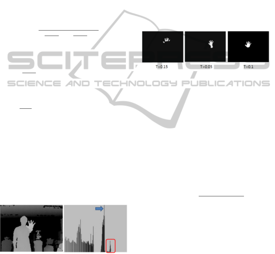
Figure 1: Input Image from a depth camera and histogram
for the depth information.
Depth information from Kinect camera is
presented in the left of figure 1 and the depth
histogram of the image is presented in the right of
figure 1. The arrow in the histogram image
represents a peak that corresponds to the body of a
human. The hand region is presented with the red
rectangle in the figure 1. The hand region is
extracted by
,
1
,
∗
0,
,
(5)
where
,
,
and T are the depth in (x,y), the
peak of a histogram and a threshold, respectively.
The region that satisfies
,
1
is classified as
the parts of the hand region. The region is extracted
on two constraints. A human hand has to be in front
of body, and there must be no object between a
camera and a hand.
Figure 2: Hand region extraction according to the
thresholds of histogram peak.
The results of hand region extraction according
to the threshold of the depth histogram are presented
in figure 2. When the threshold T=0.1, the best result
is obtained by experiments.
3.2 Pose Normalization
After extracting the region of a hand, the noise
elimination is performed by the median filtering and
the centroid of a hand is calculated to normalize a
hand image. The radius of the outer circle of a hand
region is computed by finding the distance of the
farthest pixel from the center of mass, which is
defined as
,
(6)
where
,
and (
,
are x, y coordinate of the
center of mass and the coordinate of contour pixel,
respectively. We can normalize a detected hand
region to fit a unit circle to have the same size for all
input images and equation is defined as
2
∗
2
,
(7)
where
and
are the size of an input image and
the size for normalization, respectively.
The hand images before and after normalization are
shown in figure 3. In order to recognize real-time
gestures using the normalized hand images, the hand
has to be tracked. In this paper, to recognize gestures
we only track the center of a hand, because we
VISAPP2014-InternationalConferenceonComputerVisionTheoryandApplications
552
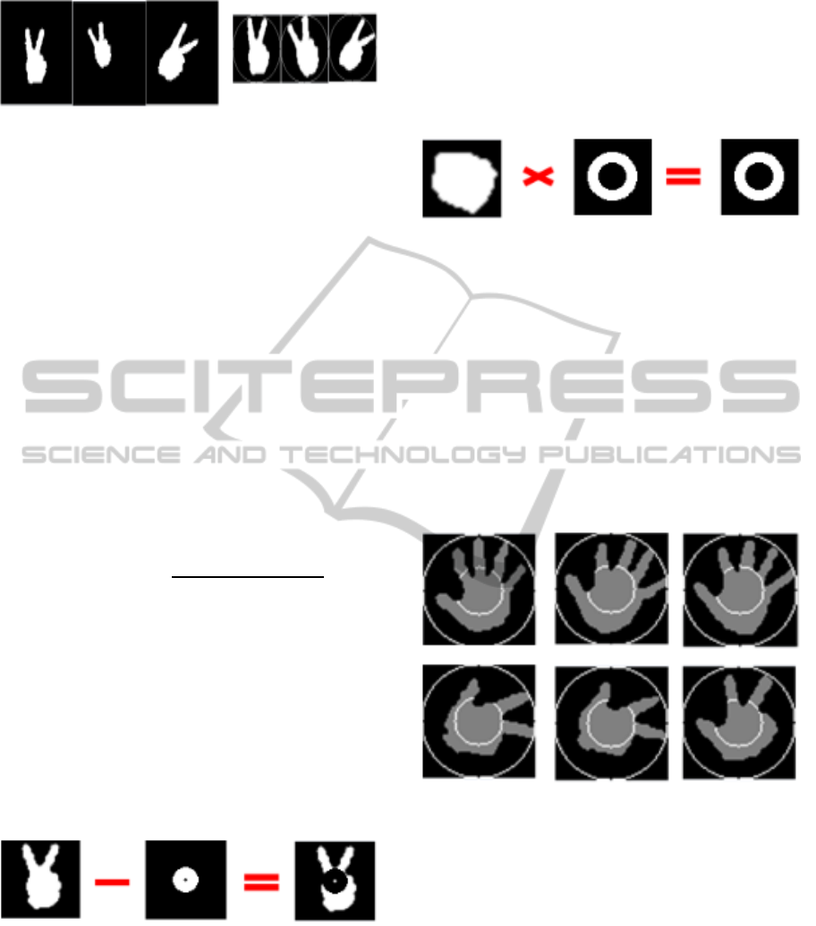
Figure 3: Hand images before and after normalization
focus on recognizing the pose of a hand without
trajectory information.
4 MASKED ZERNIKE MOMENTS
4.1 Elimination of Redundancy
Information
Zernike moments obtained from all of image pixels
are frequently used for the image classification.
However, much image information is overlapped in
the specific area due to the characteristic of the hand
image. Therefore, in order to improve the power of
discrimination on the Zernike moments, we use
internal mask R1 which eliminates redundant
information. The size of R1 mask has to be small
enough to fit the inner circle of a hand. The equation
of calculating radius of the inner circle is defined as
(8)
We use the contour image of a normalized image,
to calculate equations (6) and (8) simultaneously.
The value obtained from equation (8) represents the
radius to bound R1 mask. The ratio between inner
and outer radius of the masks is set to 0.25. The
reason why we used a ring mask instead of a circle
mask is that the size of an inner circle is different
with distances, even though same people makes the
same posture. The sample of hand image masked by
R1 ring is presented in figure 4.
Figure 4: Hand image applied by internal mask R1.
There is an exceptional case when R1 ring mask
and R2 ring mask are overlapped (see figure 5) and
the condition to detect the exception is defined as
1
,
1
∗0.5
0,
.
(9)
Usually, the area of internal mask R1 is smaller than
0.5 ratio of the unit circle by the normalization. On
the other hand, in case of the rock pose the outer
boundary of R1 ring is over 0.5 ratio of the unit
circle. So, we use the ratio in range 0.375 - 0.625 of
unit circle for the boundary between R1 ring and R2
ring, and an exceptional hand image is presented in
figure 5.
Figure 5: Exceptional hand pose applied to R1 ring mask.
4.2 Weighting of Important Feature
We eliminated overlapped information of hand
image using internal mask R1 ring in the previous
section. External mask R2 is to weigh importance
that is able to improve power of discrimination. In
this paper, we define the inner boundary size of R2
ring as 0.5 of the unit circle, since the ratio between
inner circle and outer circle is 0.44 from the
geometrical characteristics of fingers. Figure 6
shows inner boundary circles for R2 ring presented
in bright gray.
Figure 6: Inner boundary circle for R2 ring mask.
When using the ratio of 0.5, since the lengths of
fingers are different, inner boundary circle crosses
above the finger joints.
For a similar reason, we define the outer boundary
of R2 ring as 0.75 ratio of the unit circle. In case of
the thumb, it has large degrees of freedom than other
fingers, which is presented in figure 7.
Therefore R2 ring mask is designed to pass
through the area of 0.5 - 0.75 of the unit circle and
its conceptual drawing is presented in figure 8.
HandPoseRecognitionbyusingMaskedZernikeMoments
553
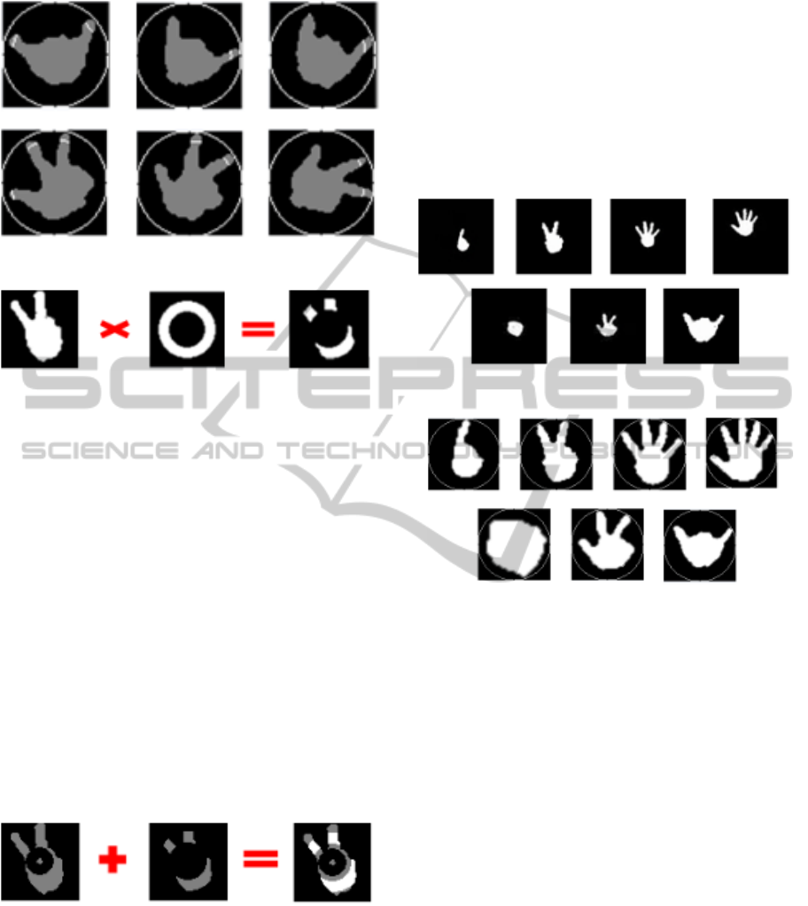
Figure 7: Outer boundary circle for R2 ring mask.
Figure 8: Hand image applied to R2 ring mask.
4.3 Zernike Moments Masked by Dual
Ring
When we use the image obtained by applying R1
ring mask and R2 ring mask, its matching result is
better than the result by using the original image on
Zernike moments. However, for the same order
Zernike moments it needs two times more
computation. Therefore to improve the efficiency we
design R3 ring mask by combining R1 ring mask
and R2 ring mask. The image obtained from combed
mask R3 is the combination of images from R1 and
R2 masks and its implementation is defined as
3 1∗
2∗
.
(10)
Where
and
are weights for images from R1
and R2 ring masks, respectively. 0.5 is used for
weights in the experiments. The result of combined
mask R3 is presented in figure 9.
Figure 9: Hand image applied to combined mask R3.
5 EXPERIMENTAL RESULTS
In order to evaluate the performance of the pose
recognition using proposed Zernike moments
masked by dual rings, we conduct comparative
experiments for seven different poses.
In the experiments seven different poses are used
and each pose contains 50 examples. So, the number
of total samples in the dataset is 350. Some of
unnormalized poses used in the experiments are
presented in figure 10. Since the native Zernike
moments are only rotation invariant, we normalize
an image for the invariance of scale and translation.
Some of normalized seven poses of 65*65 sizes are
presented in figure 11.
Figure 10: Unnormalized seven different poses.
Figure 11: Normalized seven different poses (images from
upper left to right indicate pose 1-4 and images from lower
left to right present pose 5-7).
Simple Euclidean distance is used for the pose
classification. An input image is classified as the
corresponding pose having smallest value in the
distance.
The average recognition rates of Zernike
moments by orders from 5 to 15 are presented in
figure 12. It is clear that the order of Zernike
moments and the recognition accuracy are not
absolutely relative. However, because the basis
function of Zernike moments is very complex,
required computation increases exponentially
according to the orders. There have been many
works to reduce the amount of execution. In our
work, we use q-recursive method (Chong, 2003) for
fast computation. By considering the recognition
accuracy and the average execution time, we use
eight orders for Zernike moments in the experiments.
VISAPP2014-InternationalConferenceonComputerVisionTheoryandApplications
554
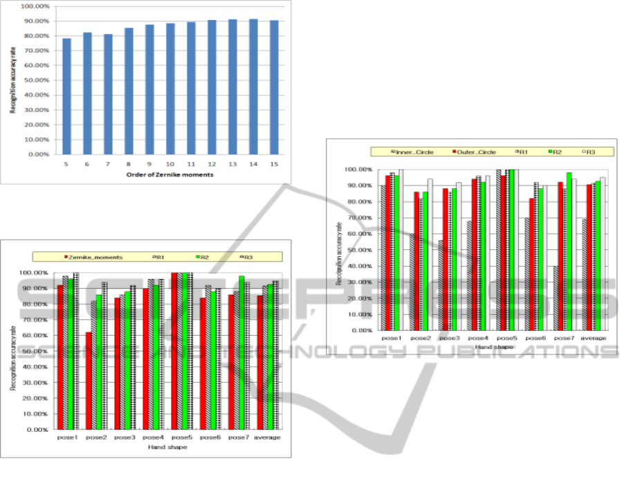
Figure 12: Average recognition rate according to the
orders of Zernike moments.
Figure 13: Recognition rate according to masks.
In figure 13, average recognition rates of Zernike
moments are presented. Recognition accuracy for
original image, image masked by R1 ring, image
masked by R2 ring and image masked by R3 are
85.43%, 91.71%, 92.57% and 95.14 %, respectively.
Since there is much redundant information near the
center of mass due to the characteristic of a hand,
internal mask R1 is applied and the recognition rate
is improved around 6.29%.
External mask R2 ring is used to weigh the
important area to improve the discrimination and
7.14% of recognition improvement is achieved.
Recognition accuracy for the image masked by
combined R3 mask is improved around 10% in
comparison with the original image. This is because
redundant information is eliminated by R1 mask and
distinctive areas are weighted by R2 mask.
To reveal the effectiveness of the proposed
method, we compare the proposed masks with
existing inner and outer circle methods (Kim, 1999).
Figure 14 presents the results of recognition rates for
existing methods and our proposed masks. The
methods of inner and outer circles treat importantly
for the area between inner and outer circles. Poor
recognition accuracy is found for the inner circle
method, since there are large overlapped region in
the center of a hand.
In case of the outer circle method, recognition
accuracy is 21% superior to the inner circle method,
which is slightly less accurate (5%) than the
accuracy by R2 or R3 mask.
Figure 14: Recognition rates compare to existing methods.
6 CONCLUSIONS
In this paper, we propose a hand pose recognition
method using Zernike moments masked by dual
rings. The proposed method consists of three masks.
Internal mask R1 eliminates redundant information
of hand images and external mask R2 enhances the
important region to improve distinctive features. R3
mask combines advantages of R1 mask and R2 mask.
In order to prove the superiority of proposed
method, we conducted comparative experiments of
pose recognition with other existing methods. As a
result, the recognition accuracy by the proposed
masks is improved around 10% against the original
image with Zernike moments and 5% increase in
comparison to the conventional method.
The processing time to calculate the Zernike
moments can be decreased by using the principle
component analysis and the proposed recognition
method will be applied to real-time applications.
ACKNOWLEDGEMENTS
This work was supported by the National Research
Foundation of Korea (NRF) Grant funded by the
Korean Government (MOE)(2013-009166).
HandPoseRecognitionbyusingMaskedZernikeMoments
555

REFERENCES
Chong, C. W., Raveendran, P., Mukundan, R., 2003, "A
comparative analysis of algorithms for fast
computation of Zernike moments," Pattern
Recognition, vol. 36, no. 3, pp. 731-742, March.
Khotanzad, A., Hong, Y. H., 1990, "Invariant image
recognition by Zernike moments," IEEE Transactions
on Pattern analysis and Machine Intelligence, vol. 12,
no. 5, pp. 489-497, May.
Kim, J. D., Kim, H. G., 1999, “Zernike Moments Shape
Descriptor with Region Partitioning”, The Korean
Society of Broadcast Engineers, pp. 53-57, Nov.
Swets, D., 1996, "Using discriminant eigen features for
image retrieval," IEEE Transaction on Pattern
Analysis and Machine Intelligence vol. 18, no. 8, pp.
831-836, Aug.
Teh, C. H., Chin, R T., 1988, "On Image Analysis by the
methods of moments," IEEE Transactions on Pattern
Analysis and Machine Intelligence, vol. 10, no.4, pp.
496-513, Jul.
Yun, J. H., Lee, C. H., 2010, “Design of Computer Vision
Interface by Recognizing Hand Motion”, The Institute
of Electronics Engineers of Korea, vol. 47, no. 3, pp.
256-265, May.
VISAPP2014-InternationalConferenceonComputerVisionTheoryandApplications
556
