
Generic and Real-time Detection of Specular Reflections in Images
Alexandre Morgand and Mohamed Tamaazousti
Vision & Content Engineering Laboratory, CEA LIST, Gif-sur-Yvette, France
Keywords:
Real-time, Generic, Specular Reflection Detection, HSV, Saturation, Value, Contrast, Gradient, Gravity
Center.
Abstract:
In this paper, we propose a generic and efficient method for real-time specular reflections detection in images.
The method relies on a new thresholding technique applied in the Hue-Saturation-Value (HSV) color space.
A detailed experimental study was conducted in this color space to highlight specular reflections’ properties.
Current state-of-the-art methods have difficulties with lighting jumps by being too specific or computationally
expensive for real-time applications. Our method addresses this problem using the following three steps: an
adaptation of the contrast of the image to handle lighting jumps, an automatic thresholding to isolate specular
reflections and a post-processing step to further reduce the number of false detections. This method has been
compared with the state-of-the-art according to our two proposed experimental protocols based on contours
and gravity center and offers fast and accurate results without a priori on the image in real-time.
1 INTRODUCTION
Depending on the desired application, specular re-
flections present advantages and drawbacks in the
computer vision community and are subject of many
years of studies ((Shafer, 1985), (Blake and Brelstaff,
1988), (Saint-Pierre et al., 2011)). Indeed, they give
accurate information for light sources modeling by
being defined as a trace of the light sources. This
property allows to understand and model light behav-
ior in a scene. For image processing, operations such
as segmentation, detection or matching, the presence
of specular reflections can disrupt results.
Dealing with specularities in computer vision
presents numerous and diversified applications. For
example, in color segmentation such as in (Deng
et al., 1999), specular reflections are often considered
as disturbing and create discontinuities in the seg-
mentation process. In the medical field, they produce
false positives in abnormality detection applications.
Therefore, they are removed by inpainting methods
((Lee et al., 2010), (Oh et al., 2007), (Saint-Pierre
et al., 2011) and (Stehle, 2006)). Conversely, impor-
tant scene information could be extracted from them
to analyse a surface shape (Blake and Brelstaff, 1988)
and compute 3D position of the light source, identify
surface smoothness, granularity or aspect (mirror-like
or glossy surfaces) and could be used for camera lo-
calization (Lagger et al., 2008). Moreover, specular
reflections are essential elements for a realistic ren-
dering in image synthesis ((Karsch et al., 2011) and
(Sillion and Puech, 1989)), or Augmented Reality ap-
plications (Jachnik et al., 2012). Lighting effects such
as shadow casting or global illumination on a virtual
object improve drastically the rendering quality.
Nevertheless, detection of specular reflections is
a challenging task: handling reliably large range of
brightness (high contrasts, dark or bright images) and
different light sources of various intensities are com-
plex issues. Therefore, state-of-the-art methods are
very specific and mostly limited to their chosen field
of applications. However, specularities present many
features common in all of these field of applications
but finding these features in an image could represent
a high computational cost. Our method targets a large
range of field of application without a priori on the
lighting conditions running in real-time by using sim-
ple but effective properties of specular reflections.
In this paper we present the related methods used
for specularity reflections detection by highlighting
the different applications targeted and results along
their limitations. These methods are divided in two
approaches: (offline 2.1 and online 2.2 detection). In
the section 3, our proposed method without a priori
is described by highlighting the reliability, efficiency
and genericity of the method in real-time. The pre-
processing section 3.2 details our contrast equaliza-
tion algorithm to handle oversaturated images.
In 3.3, our automatic thresholding method is pre-
sented to handle different lighting conditions increas-
274
Morgand A. and Tamaazousti M..
Generic and Real-time Detection of Specular Reflections in Images.
DOI: 10.5220/0004680102740282
In Proceedings of the 9th International Conference on Computer Vision Theory and Applications (VISAPP-2014), pages 274-282
ISBN: 978-989-758-003-1
Copyright
c
2014 SCITEPRESS (Science and Technology Publications, Lda.)

ing the genericity of our method. In the post-
processing 3.4 section, by using the gradient aspect of
specularities, misdetected specularities are removed.
Our results are presented and compared in 4 with the
method of (Arnold et al., 2010) to point out efficiency
and genericity of our method.
2 RELATED WORKS
Specular reflections detection is usually divided in
three processes: pre-treatment to handle noise and
different lighting conditions, thresholding to isolate
specularities by using a predefined or automatically
computed thresholds and a post-treatment process
to remove misdetected specularities or find missing
ones. These steps were used in Table.1 along other
criteria such as the color space used and input type
(video or image) to give an accurate overview of the
state-of-method methods as well as our approach.
2.1 Offline Approaches
(Stehle, 2006) used a thresholding on the YUV color
space where Y represents the brightness and U, V
are the chrominance channels. By thresholding the Y
channel at the last peak in the Y histogram, specular-
ities are isolated. According to (Stehle, 2006) a small
peak corresponding to specular reflections’ pixels can
be found on the right hand side of the histogram. This
method is used in endoscopic imaging where the con-
text of work is darker and the dynamic range of im-
ages is generally well distributed. Nevertheless, with
images specular-free, using this method could pro-
duce misdetections such as white objects and images
with specularities does not have necessarily a peak at
the end of the histogram.
(Oh et al., 2007) consider specular reflections as a
reflection from a smooth shiny surface visually repre-
sented as absolutely bright regions. These highlights
(a) Specular reflections (b) Complex case of specular reflec-
tions
Figure 1: (a) Example of specular reflections on a plane
surface: five specularities can be seen and stand out to the
eye as saturated elements. (b) Example of a complex case
of specular reflections: specularities appeared on the ring in
the bottom-middle and on the table in the middle.
appeared as at least one saturated color which is vi-
sually white as shown in Fig.1(a). In their method,
the image is transferred into the Hue-Value-Saturation
color space because it is less sensitive to the noise.
Firstly, these Absolute Bright regions are isolated by
two thresholds on the Value and Saturation channels
and Hue is left aside because the hue of a saturated
color is not defined.
Secondly, a color quantization and a spatial seg-
mentation is applied cutting the image into k regions.
By using the same thresholding method on the k re-
gions, they obtained two areas called Absolute Bright
Areas and Relative Bright Areas.
The merging of Absolute Bright Areas and Rel-
ative Bright Areas gives reliable results but using a
segmentation method has a algorithmic complexity of
O(n
2
). Moreover, with Relative Bright Areas, it is
possible to detect white surfaces which are not specu-
lar reflections.
Machine learning, dimensionality reduction and
optimization algorithms could be used to isolate spec-
ular reflections. (Park and Kak, 2003) proposed a
Truncated Least Squares approach to map color dis-
tribution between images of an object under different
illuminations to detect specular highlights. (Lee et al.,
2010) uses a perceptron neural networks to classify
specular regions. These methods offer good results
but are well known for their computationally cost.
(Torres et al., 2003) and (Ortiz and Torres, 2006)
highlighted the importance of using a specific color
space such as HSV because the perception system of
the human brain uses basic attributes of color such
as intensity, hue and saturation. They work in a bi-
dimensional histogram called the MS diagram and use
thresholding to isolate specularities. An histogram
equalization is used to keep the threshold constant.
These methods give accurate and fast results but us-
ing a histogram equalization could lead to false detec-
tions because operations which highlight outliers such
as the top-hat contrast operator enhance specularities
but white surfaces and noise as well. Even if arti-
facts can often be removed by using morphological
transformations such as dilation, these morphological
operations have an algorithmic complexity of O(n
2
)
which can be problematic when dealing with video
streams for an online detection. Moreover, a specular
reflections can appear fragmented into smaller specu-
larities and could be removed by morphological oper-
ations like erosion.
2.2 Online Approaches
Many fields require real-time method for specular-
ity detection such as medical (Arnold et al., 2010) or
GenericandReal-timeDetectionofSpecularReflectionsinImages
275
Augmented Reality ones (Jachnik et al., 2012).
(Arnold et al., 2010) give another approach of
specularities detection problem using threshold in the
RGB color space and a gray-scale image. In the RGB
color space, saturated blue, red or green are con-
sidered as specular reflections. Instead of setting a
constant global threshold like in (Oh et al., 2007),
(Arnold et al., 2010) use an adaptive threshold com-
puted from the green and blue color channels to iso-
late the specular reflections. Another step of thresh-
olding is used to find missed outliers using a modified
median filter and a more tolerant thresholding.
The post-processing stage computes the contours
of the specular reflections and removes areas of sub-
stantial size because they are more likely to be bright
regions and not specular reflections.
For endoscopic imaging, this method is reliable
and relatively fast but is lacking genericity and is very
sensitive to white surfaces. Moreover, endoscopic
systems allow to have an accurate control on the light
source and provide an efficient automatic exposure
correction which ensure to avoid over/underexposure
cases.
3 PROPOSED METHOD
3.1 Overview
Our method is aimed to avoid limitations in the specu-
larities detection. The goal is to handle multiple light-
ing sources with different intensities in real-time. We
do not assume the histogram of the image well equal-
ized. Conversely, every lighting issue occurring in a
video stream has to be taken into account (as seen in
Fig.2(a) and Fig.2(b)). No a priori on the specular-
ity size is assumed, bright regions (called Lambertian
surfaces
1
) has to be left aside but specularities due
to the sun, which has generally a significant size (see
Fig.2(d)) must be detected. Our detector must be fast
enough to be used in real-time applications.
The color space choice is justified by the behavior
of the human eye. A human eye is more sensitive to
the blue, green and red zones in order to compute the
visual aspect of an object. However, in the perception
process of the human brain, the amount of red, green,
and blue in objects is not precisely estimated. Instead,
basic attributes of color such as intensity, hue, and
saturation are used (Ortiz and Torres, 2006). Thus,
we decided to work in the HSV color space because
specularities stand out naturally in it (see Fig.3) and
two criteria can be used in the HSV color space (see
1
see (Lambert and DiLaura, 2001) for more details
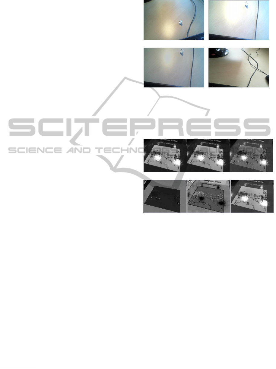
(a) (b)
(c) (d)
Figure 2: Different cases of specularities: (a) shows the nor-
mal case with good dynamic range. The specularity can be
seen on the ring, (b) presents the oversaturated case which
is in unusable state, (c) shows the image (b) after our con-
trast equalization (d), shows a specularity created by the sun
which should be detected.
(a)
(b)
Figure 3: Specularities follow one criterion in the RGB
color space, in the form of white spots. Two criteria can
be used in the HSV color space, finding black spots in the
Saturation channel and white spots in the Value channel. In
(a) RGB channels decomposition, specularities appeared in
the three channels Red (left), Green (middle) and Red (left)
as bright and white spots. In (b), HSV channels decompo-
sition, specularities can not be seen in the Hue channel (on
the left) but clearly in the Saturation channel (in the mid-
dle) as black spots and in the Value channel (on the right)
as bright and white spots.
Fig.3(b)) as opposed to one criterion in the RGB color
space (see Fig.3(a)). Indeed, in the HSV color space,
specularities are characterized by a low saturation and
a high value whereas in the RGB color space, they are
represented by white surfaces.
3.2 Pre-processing
Saturated images often result (Fig.2(b)) in misdetec-
tion and are in unusable state. Therefore, a contrast
equalization is applied to this image by measuring
VISAPP2014-InternationalConferenceonComputerVisionTheoryandApplications
276
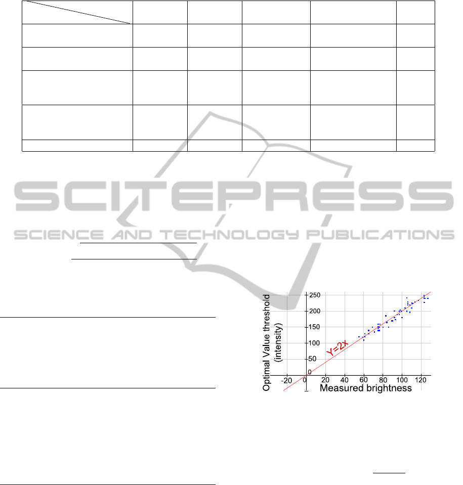
Table 1: Main state-of-the-art method classification and positioning of our method.
Table 1: Main state-of-the-art method classification and positioning of our method.
Methods
Properties Color
space
Threshold
Pre-treatment Post-treatment
Video/
Image
(Ortiz and Torres, 2006)
MS constant
Histogram
equalization
Morphological
operations
Image
(Stehle, 2006)
YUV automatic None
Morphological
operations
Image
(Oh et al., 2007)
HSV constant
Top hat
operator
Segmentation and
Morphological
operations
Image
(Arnold et al., 2010)
RGB
+
gray scale
automatic None
Morphological
operations
Video
Our method HSV automatic Contrast Gradient Video
3.2 Pre-processing
Saturated images often result (Fig.2(b)) in misdetec-
tion and are in unusable state. Therefore, a contrast
equalization is applied to this image by measuring
the brightness of the image as defined in Eq.(1). If
this value is above a certain threshold T
b
(brightness
threshold), the image is considered as saturated and
the contrast is lower (see Algorithm.1). The result of
this algorithm can be seen in Fig.2(c).
Brightness =
q
0.241∗C
2
R
+0.691∗C
2
G
+0.068∗C
2
B
Width∗Height
(1)
The brightness is a relevant factor to use for auto-
matic thresholding because an increase in the bright-
ness causes an increase in the Value channel.
Algorithm 1 Contrast equalization algorithm. Aver-
age brightness corresponds to a value of 80. We no-
ticed that saturated images in our training database
had a brightness above 125. Due to the uncertain na-
ture of oversaturated images, T
b
is set to 125 in order
to limit false detections to the maximum possible.
contrast = 1;
if Brightness ≤ T
b
then
while Brightness ≤ T
b
do
Contrast ← Contrast − 0.01;
Image
pixels
* Contrast;
Compute(Brightness);
end while
end if
3.3 Thresholding process
To deal with different lighting conditions and con-
trasts, we can apply an histogram equalization on the
Value channel. However, as (Ortiz and Torres, 2006)
pointed out that contrast enhancement is not the best
solution as it can sometimes cause oversaturation and
an excessive increase in intensity resulting in a false
detection of specularities. Therefore, instead of hav-
ing constant thresholds (as in (Oh et al., 2007) and
(Ortiz and Torres, 2005)), our Value threshold is esti-
mated dynamically by using brightness and informa-
tion in the Value channel histogram. On a training
database of 50 samples of greatly varied images with
different sizes, contrast, lighting context and light-
ing intensities, a relation of proportionality with k
was found experimentally between the brightness (see
Eq.(2)) and T
v
which is our threshold Value. For each
image, an optimal T
v
was manually estimated (see
Fig.4).
Figure 4: By comparing the optimal threshold value with
the associated brightness value, we can see clearly that our
50 test images database (represented as blue squares in the
image) follows the linear function y = 2x (red line in the im-
age), showing the proportionality between T
v
and the global
Brightness.
the brightness of the image as defined in Eq.(1). If
this value is above a certain threshold T
b
(brightness
threshold), the image is considered as saturated and
the contrast is lower (see Algorithm.1). The result of
this algorithm can be seen in Fig.2(c).
Brightness =
q
0.241∗C
2
R
+0.691∗C
2
G
+0.068∗C
2
B
Width∗Height
(1)
The brightness is a relevant factor to use for auto-
matic thresholding because an increase in the bright-
ness causes an increase in the Value channel.
Algorithm 1 : Contrast equalization algorithm. Average
brightness corresponds to a value of 80. We noticed that
saturated images in our training database had a brightness
above 125. Due to the uncertain nature of oversaturated im-
ages, T
b
is set to 125 in order to limit false detections to the
maximum possible.
contrast = 1;
if Brightness ≤ T
b
then
while Brightness ≤ T
b
do
Contrast ← Contrast − 0.01;
Image
pixels
* Contrast;
Compute(Brightness);
end while
end if
3.3 Thresholding Process
To deal with different lighting conditions and con-
trasts, we can apply an histogram equalization on the
Value channel. However, as (Ortiz and Torres, 2006)
pointed out that contrast enhancement is not the best
solution as it can sometimes cause oversaturation and
an excessive increase in intensity resulting in a false
detection of specularities. Therefore, instead of hav-
ing constant thresholds (as in (Oh et al., 2007) and
(Ortiz and Torres, 2005)), our Value threshold is esti-
mated dynamically by using brightness and informa-
tion in the Value channel histogram. On a training
database of 50 samples of greatly varied images with
different sizes, contrast, lighting context and light-
ing intensities, a relation of proportionality with k
was found experimentally between the brightness (see
Eq.(2)) and T
v
which is our threshold Value. For each
image, an optimal T
v
was manually estimated (see
Fig.4).
Figure 4: By comparing the optimal threshold value with
the associated brightness value, we can see clearly that our
50 test images database (represented as blue squares in the
image) follows the linear function y = 2x (red line in the im-
age), showing the proportionality between T
v
and the global
Brightness.
Thus, we computed the ratio
T
v
Brightness
to estimate
k
v
.
T
v
= Brightness ∗ k
v
. (2)
The Saturation threshold T
s
was set at a constant value
because Saturation’s behavior is depending on the
color and brightness presenting difficulties to use in
specularities detection. Our thresholding conditions
is presented in Eq.(3).
if S(x) < T
s
and V (x) > T
v
, (3)
with S(x) and V (x) the Saturation and Value of the
pixel x. Moreover, when oversaturation occurred, by
GenericandReal-timeDetectionofSpecularReflectionsinImages
277

watching the saturated value of the Value channel
(with the value 255 in the histogram), we adjust au-
tomatically these thresholds following this formula
(Eq.(4)):
if Histogram
Value
(255) > (Image
size
/3)
T
s
= 30 and T
v
= 245.
(4)
The thresholding step produces robust results un-
der difficult conditions and allows a better control on
the context. Indeed, we can disable the specularities
detection if the image is oversaturated (high bright-
ness) during lighting jumps to avoid false detections
and provide reliability in a real-time application.
3.4 Post-processing
Even with our contrast equalization, some areas are
still misdetected when the image is oversaturated (for
example the piece of paper on the right as in Fig.5(a)).
We rely our post-processing on a new property of
specularity reflections: gradient (see Fig.5(d)) which
is represented in the HSV color space. The gradient
discriminates effectively the specularity from a white
region misdetected. In a first time, a division of the
result image into k regions of specularity candidates
is applied (Fig.5(b)). This segmentation is done using
(Suzuki and Satoshi, 1985) algorithm. We took the
biggest square for each contour because a specularity
can have small fragments around it and it is more rele-
vant to include them in the calculus. In a second time,
(a) (b)
(c) (d)
Figure 5: (a) Oversaturated image: the paper has an aspect
very close to the specularity and could be misdetected as
a specularity. (b) Isolation of the candidates for specular-
ities of the figure (a). (c) Specularity seen in RGB color
space. (d) Gradient property represented in the HSV color
space. The gradient is clearly highlighted and discriminates
the specularity from the white region in the top of the pic-
ture.
by modifying the thresholds T
s
and T
v
, we will com-
pute the area for each step to study its evolution. If
this evolution is constant (decreases linearly over the
time regularly (see Fig.6(a)) or the variation is null
(see Fig.6(b)), this area is considered as a specular re-
flection. If the area decreases abruptly (see Fig.6(c)
and Fig.6(d)), the area was misdetected as a specular
reflection.
This criterion is common in every specularity but
difficult to apply on very small surfaces because the
gradient exists but is drastically smaller. Note that, in
some cases, white areas could have a gradient aspect
but this case remains rare.
3.5 Algorithmic Complexity
An algorithmic complexity study was conducted on
every step of our method (see in Table.2). The global
complexity computed is O(n +k ∗c) with n represent-
ing the number of pixels in the image, k the number of
regions found in our segmentation and c the number
of iterations during our gradient process.
Table 2: Global complexity of our method. n represents all
the pixels of the image. k is the number of regions found in
our segmentation and c the number of iterations during the
gradient thresholding.
Table 1: Global complexity of our method. n represents all
the pixels of the image. k is the number of regions found in
our segmentation and c the number of iterations during the
gradient thresholding.
Steps Complexity
Contrast equalization O(1)
Thresholding O(n)
Segmentation +
Gradient thresholding
O(n ∗ k) + O(k ∗ c)
Total: O(n + k ∗ c)
genericity of our method. In the post-processing 3.4
section, by using the gradient aspect of specularities,
misdetected specularities are removed. Our results
are presented and compared in 4 with the method of
(Arnold et al., 2010) to point out efficiency and gener-
icity of our method.
2 RELATED WORKS
Specular reflections detection is usually divided in
three processes: pre-treatment to handle noise and
different lighting conditions, thresholding to isolate
specularities by using a predefined or automatically
computed thresholds and a post-treatment process
to remove misdetected specularities or find missing
ones. These steps were used in Table.2 along other
criteria such as the color space used and input type
(video or image) to give an accurate overview of the
state-of-method methods as well as our approach.
2.1 Offline Approaches
(Stehle, 2006) used a thresholding on the YUV color
space where Y represents the brightness and U, V
are the chrominance channels. By thresholding the Y
channel at the last peak in the Y histogram, specular-
ities are isolated. According to (Stehle, 2006) a small
peak corresponding to specular reflections’ pixels can
be found on the right hand side of the histogram. This
method is used in endoscopic imaging where the con-
text of work is darker and the dynamic range of im-
ages is generally well distributed. Nevertheless, with
images specular-free, using this method could pro-
duce misdetections such as white objects and images
with specularities does not have necessarily a peak at
the end of the histogram.
(Oh et al., 2007) consider specular reflections as a
reflection from a smooth shiny surface visually repre-
sented as absolutely bright regions. These highlights
appeared as at least one saturated color which is vi-
sually white as shown in Fig.1(a). In their method,
the image is transferred into the Hue-Value-Saturation
color space because it is less sensitive to the noise.
Firstly, these Absolute Bright regions are isolated by
two thresholds on the Value and Saturation channels
and Hue is left aside because the hue of a saturated
color is not defined.
Secondly, a color quantization and a spatial seg-
mentation is applied cutting the image into k regions.
By using the same thresholding method on the k re-
gions, they obtained two areas called Absolute Bright
Areas and Relative Bright Areas.
The merging of Absolute Bright Areas and Rel-
ative Bright Areas gives reliable results but using a
segmentation method has a algorithmic complexity of
O(n
2
). Moreover, with Relative Bright Areas, it is
possible to detect white surfaces which are not specu-
lar reflections.
Machine learning, dimensionality reduction and
optimization algorithms could be used to isolate spec-
ular reflections. (Park and Kak, 2003) proposed a
Truncated Least Squares approach to map color dis-
tribution between images of an object under different
illuminations to detect specular highlights. (Lee et al.,
2010) uses a perceptron neural networks to classify
specular regions. These methods offer good results
but are well known for their computationally cost.
(Torres et al., 2003) and (Ortiz and Torres, 2006)
highlighted the importance of using a specific color
space such as HSV because the perception system of
the human brain uses basic attributes of color such
as intensity, hue and saturation. They work in a bi-
dimensional histogram called the MS diagram and use
thresholding to isolate specularities. An histogram
equalization is used to keep the threshold constant.
These methods give accurate and fast results but us-
ing a histogram equalization could lead to false detec-
tions because operations which highlight outliers such
as the top-hat contrast operator enhance specularities
but white surfaces and noise as well. Even if arti-
facts can often be removed by using morphological
(a) Specular reflections (b) Complex case of specular reflec-
tions
Figure 1: (a) Example of specular reflections on a plane
surface: five specularities can be seen and stand out to the
eye as saturated elements. (b) Example of a complex case
of specular reflections: specularities appeared on the ring in
the bottom-middle and on the table in the middle.
4 EXPERIMENTAL EVALUATION
4.1 Experimental Protocol
We compare our results with our implementation of
Arnold et al. method which is a rapid state-of-the-art
approach giving good results in real-time. Moreover,
(Arnold et al., 2010) compared their method with (Oh
et al., 2007) by pointing out efficiency and speed of
their approach. The implementation of the method
was done using (Arnold et al., 2010) parameters.
These approaches were tested on our database of
100 test images (different from our training database
used to set the different thresholds) to highlight the
genericity and efficiency of our method.
VISAPP2014-InternationalConferenceonComputerVisionTheoryandApplications
278
(a) (b)
(c) (d)
Figure 6: (a) and (b) represent the evolution of the specularity’s area (in the middle of 5(b)). (c) and (d) represent the evolution
of the white region’s area (the book on the right of 5(b)). Area evolution is computed in function of T
v
((a) and (c)) and T
s
((b) and (d)). We can see clearly that the specularity has an area slowly decreasing and regularly when T
v
is increasing and a
constant area when T
s
is decreasing. In contrast, the misdetected white has an area sharply decreasing when T
v
is increasing.
The same occurred when T
s
is decreasing.
4.2 Quantitative Evaluation
A reliable evaluation for specularities detection re-
quires a clear definition of the specular reflections’
properties. Two criteria should be highlighted: accu-
racy of the specularity’s contour and exactness of the
gravity center. The first criterion purposes to compare
the contour of a specularity evaluated by the human
eye with the output of our algorithm. Thus, a manual
contouring of the specularities on our 100 test images
database was done and compared with the contours of
the specularities detected (gray scale images as seen
in Fig.7). The contours are computed using Sobel op-
erator with a 3 × 3 kernel. A contour is considered
accurate if for each contour point, we find a pixel be-
longing in its neighborhood. This neighborhood is
represented by a 9 × 9 matrix to be strict enough and
not accept critical errors (Fig.8(a) demonstrates our
contour evaluation).
In Fig.8(b), the principle of our gravity center
evaluation is illustrated. By using our gradient sup-
position described in 3.4, a gravity center is found by
following the opposite direction of the gradient until
convergence (gradient stable or at the value of 255).
The remaining points are used to compute a centroid
more relevant than a centroid estimated with the spec-
ularity contour only. The ground truth was manually
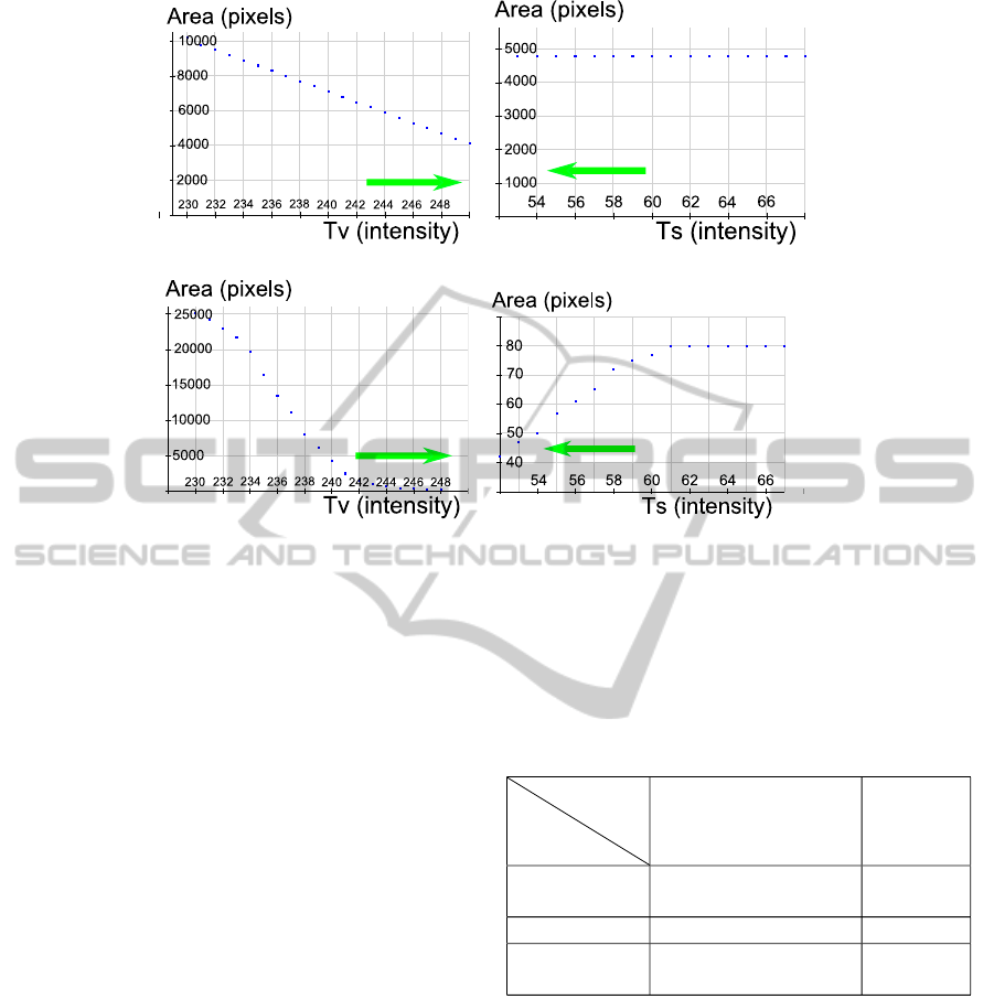
Table 3: Speed comparison between the two methods us-
ing the mean time of treatment on a single image on the
database of 100 images.
Table 3: Speed comparison between the two methods us-
ing the mean time of treatment on a single image on the
database of 100 images.
Evaluation
Method
(Arnold et al., 2010)
Our
Method
Elapsed
time
0.0584 s 0.0371 s
Contour
70.3 % 80.29 %
Gravity
center
67.2 % 78.13 %
(a) (b)
Figure 8: Our proposed evaluation methods for specularity
detection : contour and gravity center evaluation. (a) shows
differences between the two methods using the ground truth
(in green) and the current detection (in red). Common pix-
els are colored in gray. (b) illustrates the gravity center es-
timation. The red lines represent the direction vector of the
gradient around the specularity
4.3 Qualitative evaluation
Compared to (Arnold et al., 2010), noise is greatly re-
duced for all images. Fig.7(b) highlights that a spec-
ularity can appear as a very large area. Using a size
criterion as in (Arnold et al., 2010) is not relevant for
a generic approach of specular reflections detection.
5 CONCLUSION
In this paper, we present a new approach for spec-
ularities detection in images, by using simple and ef-
ficient properties of specular reflections. We use the
Value and Saturation channels in the HSV color space
to estimate automatically different thresholds based
on the global brightness of the image. Moreover, as
a pre-processing step, we propose an automatic con-
trast adjustment to handle lighting jumps and also a
gradient aspect of a specularity to manage the misde-
tected regions. Our method is then real-time, generic
and reliable for different applications. This approach
was compared with the state-of-the-art by using a new
experimental protocol based on two properties: accu-
racy of the contour and the gravity center of a specular
reflection.
6 DISCUSSION AND FUTURE
WORK
State-of-the art approaches on specular reflections
detection are threshold based methods. Nevertheless,
relying on strong reflection models such as Lamber-
tian model (Brelstaff and Blake, 1988) or separating
diffuse and specular components (Tan et al., 2004)
could be relevant to increase accuracy and noise re-
duction. Some applications such as (Jachnik et al.,
2012) and (Lagger et al., 2008) for 3D pose estimation
or refinement of the light sources or (Karsch et al.,
2011) require a real-time specular reflections detector
because they are dealing with video stream. More-
over, a video stream contains a huge amount of in-
formation to provide accurate misdetection correction
such as white textures in an image to another (see
example in (Lee and Bajcsy, 1992) or (Feris et al.,
2006)). Our method could be further improved by us-
ing multi-view information and is fast enough to han-
dle each frame in real-time.
REFERENCES
Arnold, M., Ghosh, A., Ameling, S., and Lacey, G. (2010).
Automatic segmentation and inpainting of specular
highlights for endoscopic imaging. Journal on Image
and Video Processing, 2010:9.
Blake, A. and Brelstaff, G. (1988). Geometry from spec-
ularities. International Conference on Computer Vi-
sion, pages 394–403.
Brelstaff, G. and Blake, A. (1988). Detecting specular
reflections using lambertian constraints. In Interna-
tional Conference on Computer Vision, ICCV.
Deng, Y., Manjunath, B., and Shin, H. (1999). Color image
segmentation. In Computer Vision and Pattern Recog-
nition, CVPR.
Feris, R., Raskar, R., Tan, K.-H., and Turk, M. (2006).
Specular highlights detection and reduction with
multi-flash photography. Journal of the Brazilian
Computer Society, 12(1):35–42.
Jachnik, J., Newcombe, R. A., and Davison, A. J. (2012).
Real-time surface light-field capture for augmentation
of planar specular. In International Symposium on
Mixed and Augmented Reality, ISMAR.
Karsch, K., Hedau, V., Forsyth, D., and Hoiem, D. (2011).
Rendering synthetic objects into legacy photographs.
ACM Transactions on Graphics (TOG), 30(6):157.
estimated as well. Both methods were evaluated on
the same data including images from Arnold et al. ar-
ticle and our data base of 100 different images.
Our approach proves to be about 1.5 faster than
Arnold et al.
4.3 Qualitative Evaluation
Compared to (Arnold et al., 2010), noise is greatly re-
duced for all images. Fig.7(b) highlights that a spec-
ularity can appear as a very large area. Using a size
criterion as in (Arnold et al., 2010) is not relevant for
a generic approach of specular reflections detection.
GenericandReal-timeDetectionofSpecularReflectionsinImages
279
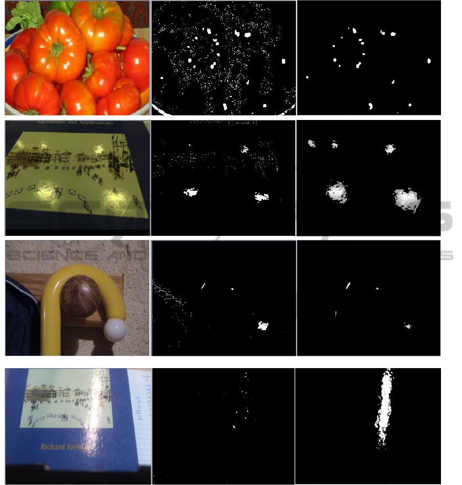
(a) Arnold et al. results in the middle: some noise is found and white is detected as a specularity. Our results, on the right, are clean and accurate
(b) Arnold et al. size criterion. The specularity detected was considered too big and was removed. Our gradient method successfully removed the unwanted
white area.
Figure 7: Specular reflections detection results of Arnold et al method (in the middle) comparing with ours (on the right).
These results were computed on our 100 test images database.
5 CONCLUSIONS
In this paper, we present a new approach for specu-
larities detection in images, by using simple and ef-
ficient properties of specular reflections. We use the
Value and Saturation channels in the HSV color space
to estimate automatically different thresholds based
on the global brightness of the image. Moreover, as
a pre-processing step, we propose an automatic con-
trast adjustment to handle lighting jumps and also a
gradient aspect of a specularity to manage the misde-
tected regions. Our method is then real-time, generic
and reliable for different applications. This approach
was compared with the state-of-the-art by using a new
VISAPP2014-InternationalConferenceonComputerVisionTheoryandApplications
280

(a) (b)
Figure 8: Our proposed evaluation methods for specularity
detection : contour and gravity center evaluation. (a) shows
differences between the two methods using the ground truth
(in green) and the current detection (in red). Common pix-
els are colored in gray. (b) illustrates the gravity center es-
timation. The red lines represent the direction vector of the
gradient around the specularity.
experimental protocol based on two properties: accu-
racy of the contour and the gravity center of a specular
reflection.
6 DISCUSSION AND FUTURE
WORK
State-of-the art approaches on specular reflections de-
tection are threshold based methods. Nevertheless, re-
lying on strong reflection models such as Lambertian
model (Brelstaff and Blake, 1988) or separating dif-
fuse and specular components (Tan et al., 2004) could
be relevant to increase accuracy and noise reduction.
Some applications such as (Jachnik et al., 2012) and
(Lagger et al., 2008) for 3D pose estimation or refine-
ment of the light sources or (Karsch et al., 2011) re-
quire a real-time specular reflections detector because
they are dealing with video stream. Moreover, a video
stream contains a huge amount of information to pro-
vide accurate misdetection correction such as white
textures in an image to another (see example in (Lee
and Bajcsy, 1992) or (Feris et al., 2006)). Our method
could be further improved by using multi-view infor-
mation and is fast enough to handle each frame in
real-time.
REFERENCES
Arnold, M., Ghosh, A., Ameling, S., and Lacey, G. (2010).
Automatic segmentation and inpainting of specular
highlights for endoscopic imaging. Journal on Image
and Video Processing, 2010:9.
Blake, A. and Brelstaff, G. (1988). Geometry from spec-
ularities. International Conference on Computer Vi-
sion, pages 394–403.
Brelstaff, G. and Blake, A. (1988). Detecting specular
reflections using lambertian constraints. In Interna-
tional Conference on Computer Vision, ICCV.
Deng, Y., Manjunath, B., and Shin, H. (1999). Color image
segmentation. In Computer Vision and Pattern Recog-
nition, CVPR.
Feris, R., Raskar, R., Tan, K.-H., and Turk, M. (2006).
Specular highlights detection and reduction with
multi-flash photography. Journal of the Brazilian
Computer Society, 12(1):35–42.
Jachnik, J., Newcombe, R. A., and Davison, A. J. (2012).
Real-time surface light-field capture for augmentation
of planar specular. In International Symposium on
Mixed and Augmented Reality, ISMAR.
Karsch, K., Hedau, V., Forsyth, D., and Hoiem, D. (2011).
Rendering synthetic objects into legacy photographs.
ACM Transactions on Graphics (TOG), 30(6):157.
Lagger, P., Salzmann, M., Lepetit, V., and Fua, P. (2008). 3d
pose refinement from reflections. In Computer Vision
and Pattern Recognition, CVPR.
Lambert, J. H. and DiLaura, D. L. (2001). Photometry, or,
on the measure and gradations of light, colors, and
shade:translation from the Latin of photometria, sive,
de mensura et gradibus luminis, colorum et umbrae.
Lee, S.-T., Yoon, T.-H., Kim, K.-S., Kim, K.-D., and Park,
W. (2010). Removal of specular reflections in tooth
color image by perceptron neural nets. In Interna-
tional Conference on Signal Processing Systems, IC-
SPS.
Lee, S. W. and Bajcsy, R. (1992). Detection of specularity
using color and multiple views. In European Confer-
ence on Computer Vision, ECCV.
Oh, J., Hwang, S., Lee, J., Tavanapong, W., Wong, J., and
de Groen, P. C. (2007). Informative frame classifica-
tion for endoscopy video. Medical Image Analysis,
11(2):110–127.
Ortiz, F. and Torres, F. (2005). A new inpainting method
for highlights elimination by colour morphology. In
Pattern Recognition and Image Analysis, pages 368–
376.
Ortiz, F. and Torres, F. (2006). Automatic detection and
elimination of specular reflectance in color images by
means of ms diagram and vector connected filters.
Systems, Man, and Cybernetics, Part C: Applications
and Reviews, 36(5):681–687.
Park, J. B. and Kak, A. C. (2003). A truncated least
squares approach to the detection of specular high-
lights in color images. In International Conference
on Robotics and Automation, ICRA.
Saint-Pierre, C.-A., Boisvert, J., Grimard, G., and Cheriet,
F. (2011). Detection and correction of specular reflec-
tions for automatic surgical tool segmentation in tho-
racoscopic images. Machine Vision and Applications,
22(1):171–180.
Shafer, S. A. (1985). Using color to separate reflection com-
ponents. Color Research & Application, 10(4):210–
218.
Sillion, F. and Puech, C. (1989). A general two-pass method
integrating specular and diffuse reflection. In Special
Interest Group on GRAPHics and Interactive Tech-
niques, SIGGRAPH.
GenericandReal-timeDetectionofSpecularReflectionsinImages
281

Stehle, T. (2006). Removal of specular reflections in en-
doscopic images. Acta Polytechnica: Journal of Ad-
vanced Engineering, 46(4):32–36.
Suzuki and Satoshi (1985). Topological structural analy-
sis of digitized binary images by border following.
Computer Vision, Graphics, and Image Processing,
30(1):32–46.
Tan, R. T., Nishino, K., and Ikeuchi, K. (2004). Separat-
ing reflection components based on chromaticity and
noise analysis. Pattern Analysis and Machine Intelli-
gence, 26(10):1373–1379.
Torres, F., Angulo, J., and Ortiz, F. (2003). Automatic de-
tection of specular reflectance in colour images using
the ms diagram. In Computer Analysis of Images and
Patterns, CAIP.
VISAPP2014-InternationalConferenceonComputerVisionTheoryandApplications
282
