Development of IR Single Mode Optical Fibers for DARWIN-nulling
Interferometry
Shahina M. C. Abdulla
1
, Lun-Kai Cheng
1
, Boudewijn v.d. Bosch
1
, Niels Dijkhuizen
1
,
Remco Nieuwland
1
, Wim Gielesen
1
, Jaques Lucas
2
, Catherine Boussard-Plédel
2
, Clément Conseil
2
,
Bruno Bureau
2
and João Pereira Do Carmo
3
1
TNO, Stieltjesweg 1, 2628 CK, Delft, The Netherlands
2
University of Rennes, Glass and Ceramic Laboratory, Campus of Beaulieu, 35042 Rennes, France
3
European Space Agency, P.O. Box 299, 2200 AG, Noordwijk ZH, The Netherlands
Keywords: Single Mode Fibers, Nulling Interferometry, DARWIN, Chalcogenide Glass, Infrared, Far Field Intensity,
Cross Core Scan, TeAsSe Fibers, TeGeGaI, Higher Order Mode Suppression.
Abstract: The DARWIN mission aims to detect weak infra-red emission lines from distant orbiting earth-like planets
using nulling interferometry. This requires filtering of wavefront errors using single mode waveguides
operating at a wavelength range of 6.5-20 µm. This article describes the optical design of the fibers, the
manufacturing protocol, the packaging for operating at cryogenic environment and various optical
characterisations performed. The latter includes investigation on the effect of gold and silver absorption
coatings, anti-reflection coating, fiber length on higher order mode suppression and attenuation of the fibers.
1 INTRODUCTION
The DARWIN mission by the European Space
Agency (ESA) (Woolf, 1998) is aimed to locate and
study earth like planets in other solar systems, in a
search for extra-terrestrial life (Kaltenegger, 2005)
.
DARWIN will consist of a nulling interferometer
(Bracewell, 1978); (Angel, 1978); (Spronck, 2012),
combining light from several telescopes that are
phase shifted from each other. This nulling
technique results in the light from a bright star being
cancelled out, leaving only light from the planets
around the star. Such a system, with capability for
imaging and spectroscopy, operating in the thermal
infrared spectral region, requires that wavefront
errors be reduced to a very high degree, in order to
achieve the required nulling quality (10
-4
to 10
-6
).
Such a high wavefront quality can only be achieved
with adequate wavefront filtering measures.
Modal filters like single mode fibers are the
preferred solution since they can filter both low and
high spatial frequencies (Bracewell, 1978); (Angel,
1978). Potential technologies for the development of
single mode fibers either using Step Index Fibers
(SIF’s) or Index Guiding Photonic Crystal Fibers
(IG-PCF’s) have been studied (Cheng, 2005)
(Zhukova, 2012) (Spronck, 2012). This article
describes the results on the development of Single
Mode Waveguides (SMW’s) based on SIF’s,
typically made of a solid material core and cladding
having slightly different refractive indices (n). For a
properly designed fiber, in the operational
wavelength range, the fundamental mode is only
guided by the core and the higher order modes
(HOMs) will experience a strong attenuation. After a
certain length of the fibre only the fundamental
mode remains. The wavelength limit for single mode
operation is mainly determined by the core diameter,
the symmetry of the core cross-section and the
difference in refractive index between core and
cladding which needs to be controlled very
accurately to achieve the required performance.
Table 1: Main requirements for the fibres to be used in
DARWIN mission.
Parameter Requirement
Operational wavelength range
6.5 to 20 m
Nr. of wavelength sub-bands ≤ 3
Total transmission > 57%
HOM suppression ratio < 10
-4
Operational temperature 40 K
Maximum SMW dimension 40 cm
Polarisation ≤ 2.5 mrad
11
M. C. Abdulla S., Cheng L., v.d. Bosch B., Dijkhuizen N., Nieuwland R., Gielesen W., Lucas J., Boussard-Plédel C., Conseil C., Bureau B. and Pereira
Do Carmo J..
Development of IR Single Mode Optical Fibers for DARWIN-nulling Interferometry.
DOI: 10.5220/0004674600110020
In Proceedings of 2nd International Conference on Photonics, Optics and Laser Technology (PHOTOPTICS-2014), pages 11-20
ISBN: 978-989-758-008-6
Copyright
c
2014 SCITEPRESS (Science and Technology Publications, Lda.)
Since in reality the cladding diameter is finite,
HOMs will be guided by the cladding. Here
additional absorption coatings will be required to
suppress these cladding modes.
The main requirements for the fibres to be used
in DARWIN mission are summarized in the Table 1.
2 FIBER DESIGN
The focus of this research programme was to
develop manufacturing techniques for a reproducible
production of single mode SIF’s, aiming to result in
wavefront filters covering the complete DARWIN
wavelength range which can be directly used in
interferometric test set-ups operating in vacuum and
cryogenic environment. To this respect two major
types of chalcogenide glass materials, potentially
suitable for SIF manufacturing in the wavelength
range of interest for DARWIN, were identified and
investigated. The first one is TeAsSe (TAS) (Cheng,
2006); (Faber, 2006) glass for the short wavelength
(SW) range (6.5 μm–12 μm). Several manufacturing
techniques were explored resulting in the
manufacturing of several SIF samples from this
material and single mode behaviour was
demonstrated by Far Field Intensity (FFI)
distribution. The relation between the composition
and the refractive index of this type of fibers were
investigated. A proper selection of the composition
of the TAS glass will result in the desired refractive
index for the core and the cladding. The default
design parameters are:
- n-core: 2.9185
- Core radius: 17.5 μm
- n-cladding: 2.9157
- Cladding thickness: 250 μm
- Numerical Aperture (NA): 0.13
- Cut-off wavelength: 5.7 μm
- Absorption coating: Gallium (Ga)
- AR coating: BaF
2
/ZnSe/BaF
2
The second type of chalcogenide glass material is
Te-based glass for the long wavelength (LW) range
(12 μm – 20 μm) for which development was less
mature. It was demonstrated that Te-glasses are
potentially suitable for fiber manufacturing purposes
but still critical with respect to processing
parameters and risk of crystallization (Cheng, 2006).
Some Te-glass based materials are investigated. The
TeGeGaI (TGGI) glass is selected for the LW fiber
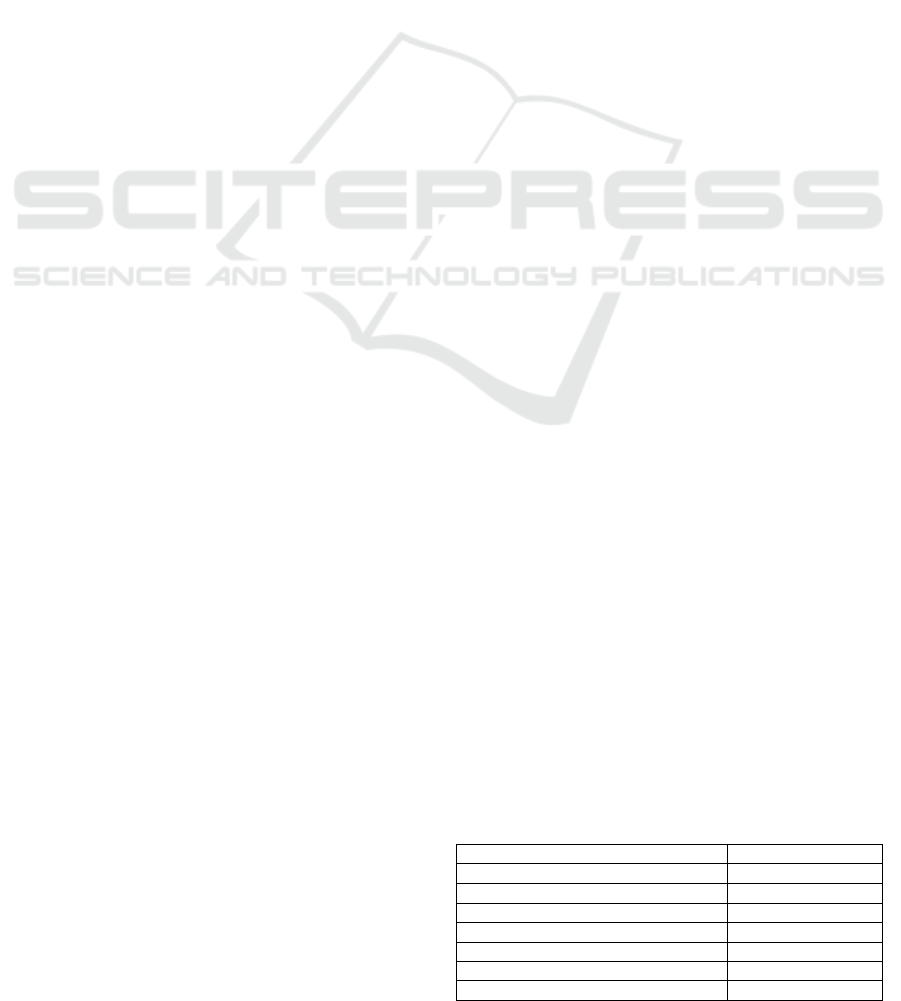
design. A typical transmission spectrum of a TGGI
glass of about 2mm is shown in Figure 1.
For the TGGI based LW fiber only a provisional
default fiber design is defined:
- n-core: 3.350
- Core radius: 15 μm
- n-cladding: 3.338
- Cladding thickness: 250 μm
- NA: 0.29
- Cut-off wavelength: 11.3 μm
- Absorption coating: Gallium
- AR coating: Not defined.
Figure 1: Transmission spectrum of TGGI shows a
transmission window up to about 19 µm.
2.1 Development of Absorption
Coating
To ensure a sufficient nulling depth, the amount of
optical power in the higher order modes at the output
of the single mode fiber must be reduced. The HOM
suppression performance depends on the thickness
of the cladding and the imaginary part of the
refractive index (k) of the absorption coating
material applied. A material with a higher k is
expected to have a higher absorption than a material
with a lower k. Though Ga was successfully
demonstrated to be a suitable coating, it was difficult
to apply a homogeneous layer. Further handling was
critical due to the low melting point of Ga. Even at
room temperature Ga becomes soft and
mechanically unstable. To find a suitable alternative
material as absorption coating, with better
manufacturability, ease in handling and stability
(and if possible better absorption), Finite Element
Modelling of the SW TAS fiber was performed by
Optoelectronics Research Centre of University of
Southampton using a commercial software package
called COMSOL Multiphysics
TM
. The TAS SW
fiber with different coating materials including Cr
(k
Cr
≈ 15 at 10.6 μm) and Ga (k
Ga
≈ 30 at 10.6 μm)
are modelled and the effect on attenuation and HOM
are calculated (Cheng, 2009).
Modelling results confirm the expectation that
k
Ga
> k
Cr
requires a shorter fiber length (L) to
PHOTOPTICS2014-InternationalConferenceonPhotonics,OpticsandLaserTechnology
12
achieve a HOM suppression of 10
6
. The modelling
also yielded that the attenuation, the fiber NA and
cut-off wavelength are unaffected by the type of
coating applied. Hence it was concluded that the
absorption coatings can be developed separately
from fiber configuration. A survey of suitable
alternative coating materials is conducted with the
following criteria:
a k close to or higher than that of Ga (further
reduction of the required fiber length).
a thermal expansion, close to TAS (to survive
temperature range down to 40 K).
clean and easy deposition method (preferably
vacuum deposition)
Finally, gold and silver were selected as absorption
coatings for the final evaluation.
2.2 Development of AR Coating
For IR single mode fibers, having a n > 2, the loss
by Fresnel reflection will be more than 11% per
fiber interface. Suitable AR coatings therefore are
required to maintain sufficient transmission. Using
thin-film modelling, TNO investigated the
performance of various AR coating configurations.
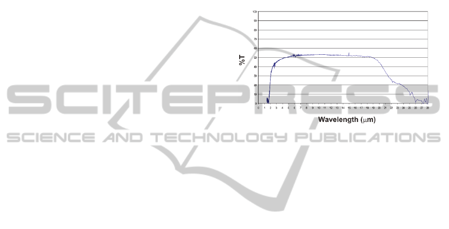
Figure 2: Demonstration of the effect of the designed AR
coating. Reflection of a bulk TAS sample (top). Reflection
of the same TAS sample with AR coating on both sides
(bottom).
A three-layer coating configuration of
BaF
2
/ZnSe/BaF
2
is considered to be a suitable
candidate for the chalcogenide TAS glass. This AR
coating design is further fine-tuned on TAS bulk
samples. Transmission and reflection of the final
configuration are measured. A TAS sample without
coating is also tested for reference. The results are
presented in Figure 2, showing a significant
reduction of the reflection of double AR coated TAS
compared to the uncoated TAS in the spectral region
6.5 – 12 m.
3 SW TAS FABRICATION
PROTOCOL
Manufacturing protocols for purification and
preparation of TAS glass and the fabrication of the
fiber are established. The right composition,
purification and temperature control are of vital
importance for quality of the parts and for the fiber
performance and hence have direct impact to the
performance of the fiber produced.
The control of the composition and hence the
refractive index of the TAS glasses is found to be
very critical. Relaxing the refractive index tolerance
is highly desirable to improve the manufacturing
yield. This results in a larger difference between the
refractive index of the core and the cladding. To
ensure single mode operation starting from 6.5 m,
the diameter of the core has also to be adapted. For
the final design, the core radius is reduced from 17.5
m to 11 m. The TAS SW fiber manufacturing
protocol using a special developed 2-steps rod-in-
tube technique is shown in Figure 3.
Figure 3: Manufacturing protocol of the TAS SW fiber.
DevelopmentofIRSingleModeOpticalFibersforDARWIN-nullingInterferometry
13
4 TAS FIBER MANUFACTURING
For the manufacturing of TAS cladding tubes,
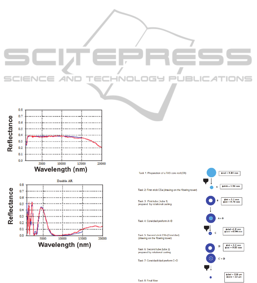
rotational casting is applied (Figure 4). The
dedicated set-up, manufacturing processes and
parameters have been calibrated and optimized as
the quality of the tube is highly influenced by the
proper levelling of the set-up, temperature during
rotational casting and rotation speed (Houizot,
2009). TAS tubes are manufactured with internal
diameter ranging from 2.8 mm – 3.2 mm.
Figure 4: Rotational casting machine and resulting TAS
tube (inset).
Based on TAS cladding glass composition and
known refractive index results, the TAS core glass
composition is defined. Purified core rods (CR)
having an external diameter of ~10 mm are
manufactured. The CR is drawn to a ø 2 mm core
stick having a length of about 60 cm (for core-clad
preform drawing) and several meters of ø 400 µm
mono-index fiber (used for fiber quality
verification).
5 CHARACTERISATION
Prior to the characterization, each SMW is visually
inspected for cracks or holes on the SMW surface
along its length. Both facets of the SMW are
carefully cleaved. The cleave which is not part of the
SMW, is further visually inspected under a
microscope to check the surface quality of the cross-
section as well as the angle of the cleave. The optical
measurements are performed using the set-up shown
in Figure 5. The source is a CO
2
laser at 10.6 µm
having a built-in Helium-Neon laser which is used
for alignment. A razor blade is used as a beam
splitter. The output power of the CO
2
laser fluctuates
about 20% (peak to peak) at 6% output power. It is
undesired to use higher power since it can damage
the fibre. Hence during the measurements, a
reference detector (with power P
ref
).is used in the
used range which is 3% - 7% of the output power.
Figure 5: Pulsed CO
2
laser set-up for fiber attenuation and
FFI characterization at 10.6 μm. They are numbered as 1-
Razor blade beamsplitter, 2- Off axis parabola, 3- Pinhole
on x,y,z stage, 4- xyz stage with SMW, A is detector A
and B is the reference detector B.
Several measurements are performed using this
set-up and detailed explanation of the results are
presented in the following sections.
PHOTOPTICS2014-InternationalConferenceonPhotonics,OpticsandLaserTechnology
14
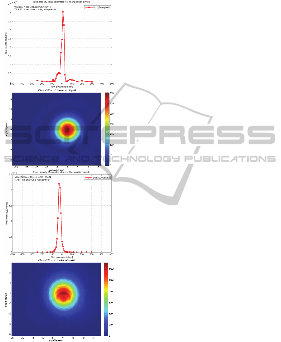
Figure 6: Cross-core and FFI performance of silver (top
two pictures, L=480mm) and gold (bottom two pictures,
L=495 mm) coated TAS fibers. The output pinhole
diameter is 100 µm and the P
ref
is 130mW in both cases.
5.1 Gold and Silver Absorption
Coatings on TAS
Due to its improved quality in manufacturability,
reproducibility, ease in handling and stability
compared to gallium, gold and silver are selected
as alternative absorption coatings for TAS fibers
in order to suppress the HOMs. Hence TAS fibers
are coated with gold and silver and are further
characterised with cross-core scan and FFI
distribution. The results of two samples (one
silver coated and the other gold coated) are shown
in Figure 6. All coated TAS samples show single
mode behaviour with an averaged NA of 0.22.
From performance point of view both gold and
silver demonstrate to be good alternatives but gold
is preferred for its durability (no oxidation) and
acceptance in space applications.
5.2 Effect of Fibre Length on Higher
Order Mode Suppression
Also the impact of reduction in fibre length to the
level of HOM suppression has been investigated.
For this, a silver coated and a gold coated sample
were selected and their lengths are reduced in
steps. Then cross-core scan and FFI distribution
were measured at each length. The silver coated
sample is reduced in 2 steps to a final length of
16.5 cm (still showing good performance with
output pinhole) and the gold coated sample is
reduced in 3 steps to a final length of 24 cm. The
results for the silver coated TAS sample at each
cut-back length are shown in Figure.
It was observed that, without pinhole, both
silver and gold coated fibers showed a decrease in
HOM suppression, with a shorter fiber length. By
using a 100 µm output pinhole, the change in
HOM suppression due to length reduction was not
observed. Apparently the output pinhole had more
effect than fiber length. The silver coated TAS
samples showed a deviation in NA for different
cutback lengths. This observation also drove to
finally select gold as preferred absorption coating
for further experiments. A consistency in NA was
observed for the gold coated TAS sample (NA =
0.20) for all cutback lengths, both “with” and
“without” pinhole.
DevelopmentofIRSingleModeOpticalFibersforDARWIN-nullingInterferometry
15
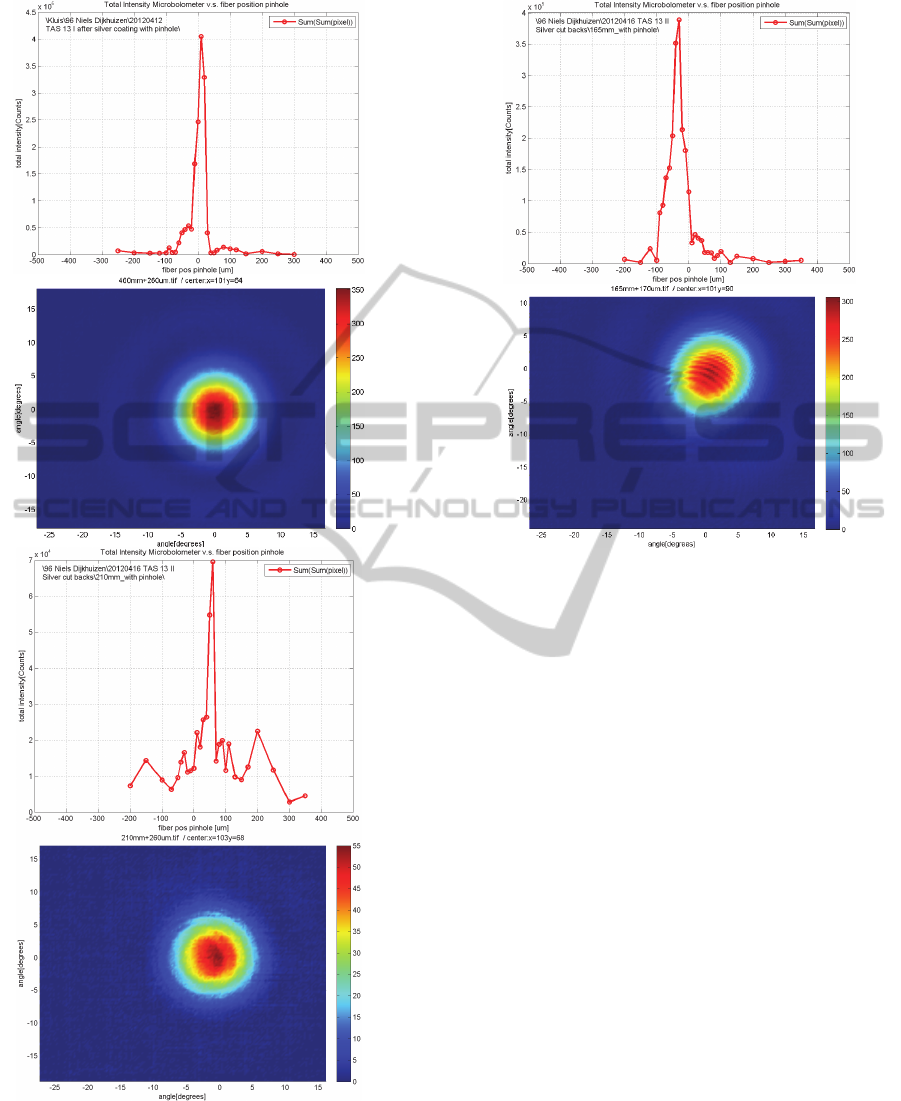
Figure 7: Cross-core and FFI results of silver coated
TAS sample at various cut-back lengths. The first and
second images are for L=480mm , the third and fourth
images are for L=210mm, fifth and sixth images are for
L=165mm. The output pinhole diameter is 100 µm. P
ref
is 130mW for L=480mm whereas P
ref
is 65mW for the
other two lengths.
Figure 7: Cross-core and FFI results of silver coated
TAS sample at various cut-back lengths. The first and
second images are for L=480mm , the third and fourth
images are for L=210mm, fifth and sixth images are for
L=165mm. The output pinhole diameter is 100 µm. P
ref
is 130mW for L=480mm whereas P
ref
is 65mW for the
other two lengths. (cont.)
5.3 Manufacturing and Testing of
Final Single Mode TAS Fibers
From a new manufactured TAS fiber batch, final
five single mode TAS fibers are characterised and
delivered to ESA. Prior to final SMF preparation
and characterization, two fiber samples, randomly
selected out of the new batch, are coated with
Gallium and subjected to incoming inspection and
characterization, proving that the new TAS batch
is of sufficiently good quality to arrive at SMW’s
for delivery. To the remaining TAS fibers from
this new batch, a gold absorption coating is
applied by vacuum deposition techniques. These
gold-coated fibers show a good mode coupling
and HOM suppression, when measured with a 100
µm output pinhole a shown in Figure 8.
PHOTOPTICS2014-InternationalConferenceonPhotonics,OpticsandLaserTechnology
16
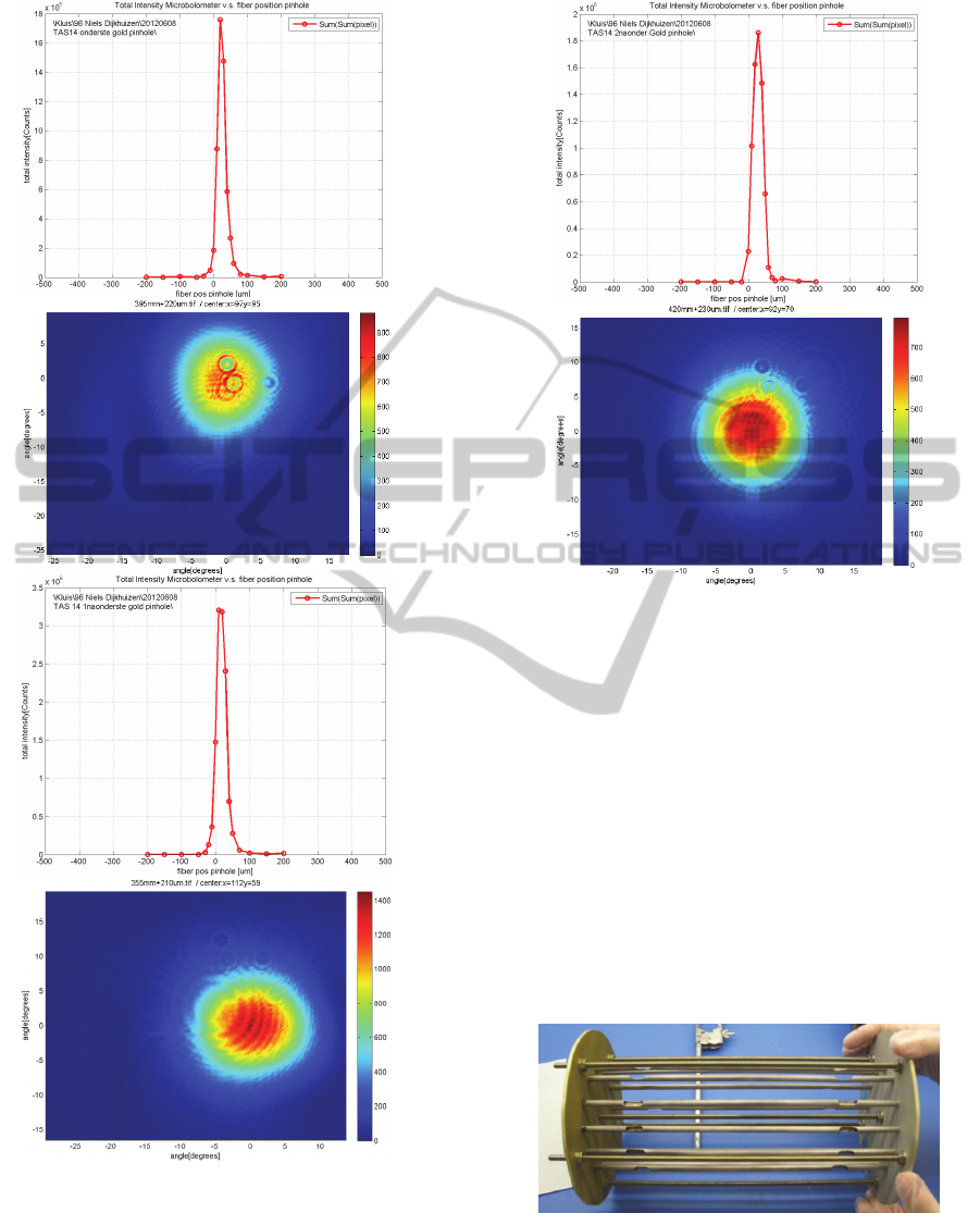
Figure 8: Cross-core and FFI results of gold coated
TAS fibers, measured with a ø 100 µm output pinhole.
The first and second images are TAS 14-10(A) with a
L=400mm, third and fourth images are for TAS 14-
11(B) with a L=350mm,fifth and sixth images are for
TAS 14-12(C) with a L=420mm.
Figure 8: Cross-core and FFI results of gold coated
TAS fibers, measured with a ø 100 µm output pinhole.
The first and second images are TAS 14-10(A) with a
L=400mm, third and fourth images are for TAS 14-
11(B) with a L=350mm,fifth and sixth images are for
TAS 14-12(C) with a L=420mm. (cont.)
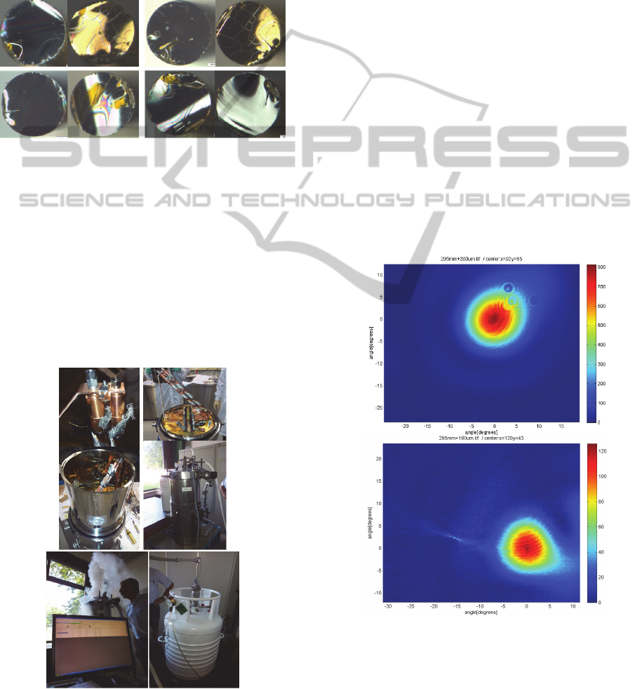
5.3.1 Anti Reflection Coating
As a next step, the three-layer BaF
2
-ZnSe-BaF
2
anti-reflection coating, initially developed by
TNO, is applied on all gold coated TAS fibers by
an external subcontracted coating facility. The
dedicated tooling for applying this coating is
shown in Figure 9. The coating uses a Ytrium
doped BaF
2
as first layer to improve bonding to
TAS.
Figure 9: Tooling used for AR coating.
Jointly with the external coating facility,
precautions were taken and arrangements were
made to optimize the fabrication process for the
DevelopmentofIRSingleModeOpticalFibersforDARWIN-nullingInterferometry
17
new special AR coating on both facets of the TAS
fibers. Due to the limited available time, the
fabrication process cannot be tested. For almost
all coated TAS fibres, the AR coating delaminated
from both fiber end facets and in some cases only
the thin first layer of Ytrium doped BaF
2
remained
on the fiber end.Figure Figure 10 shows
microscopic images of some of the fiber facets
showing delaminated AR coating.
Figure 10: Some examples of delaminated AR coating
on TAS end facets.
Cleaning of the fiber ends in an attempt to
remove the delaminating AR coating was only in
some cases successful. In most cases however the
cleaning appeared to be less effective. Hence it
was decided that cleaving of the TAS fiber end
facets is the best solution to remove the faulty AR
coatings. Thus the final single mode TAS fibers
were delivered to ESA without an AR coating.
5.3.2 Cryo Testing
Figure 11: Photographs of cryogenic test set-up and
Helium facility (SRON) for controlled 40K cycle tests.
Two gold coated TAS fibers were mounted in the
special designed cryogenic copper SMW holder
and were subjected to a controlled cryo-test (1
cycle for more than 2 hours at 40K), using a
Helium cryostat facility of Netherlands Institute
for Space research (SRON) as shown in Figure
11.
Following the cryo-cycle test, visual
inspection did not show any significant change of
the copper holders nor any failure/degradation of
the TAS fibers after de-mounting from the holder.
Microscopic inspections proved that the quality of
the fiber end facets and gold coated surfaces did
not degrade due to the 40K exposure. Also the FFI
performance remained still good after cryo-tests.
5.3.3 Copper Mounting
For delivery to ESA, five gold coated TAS fibers,
having no AR coating are selected and mounted in
the special designed cryogenic copper SMW
holders. The mounted fibers are delivered without
SMA connector interface but with the fiber end
facets protruding outside the holder for a few
millimetres at both sides of the mount.
Figure 12: Cross-core and FFI characterization of the
five packaged TAS fibers. First image is TAS 14-1 in
(Cu holder 1), second image is TAS 14-2 in (Cu holder
2), third image is TAS 14-5 in (Cu holder 3), fourth
image is TAS 14-6 in (Cu holder 5), and the fifth image
is TAS 14-7 in (Cu holder 4). The output pinhole
diameter is 100 µm and P
ref
is 100mW.
PHOTOPTICS2014-InternationalConferenceonPhotonics,OpticsandLaserTechnology
18
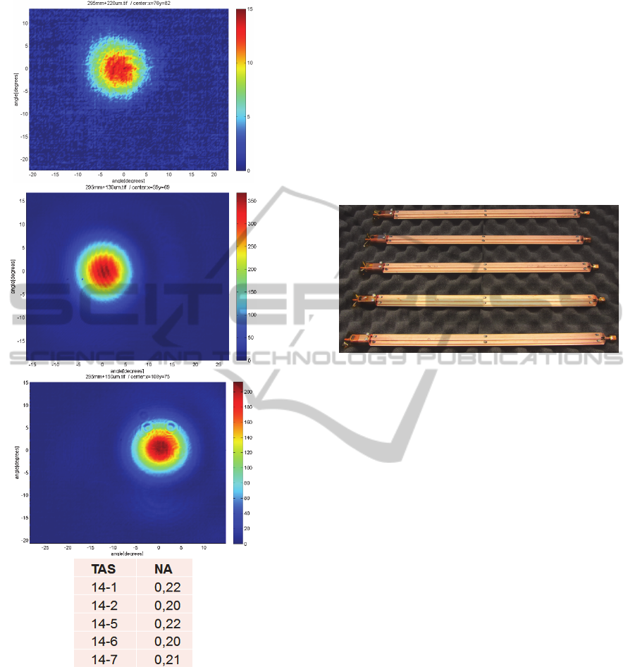
Figure 12: Cross-core and FFI characterization of the
five packaged TAS fibers. First image is TAS 14-1 in
(Cu holder 1), second image is TAS 14-2 in (Cu holder
2), third image is TAS 14-5 in (Cu holder 3), fourth
image is TAS 14-6 in (Cu holder 5), and the fifth image
is TAS 14-7 in (Cu holder 4). The output pinhole
diameter is 100 µm and P
ref
is 100mW. (cont.)
The length of these fibers range from 288 mm
to 292 mm. After packaging, the cross-core scan
and FFI distribution of each fiber was measured
and the results of it are shown in Figure 12. All
five fibers show a clear single mode behaviour.
With a 100 µm output pinhole they showed a
strong circular FFI distribution. The NA of these
fibers range from 0.20 to 0.22.
For safe transport, storage and handling (when
not in use) of the fibers, which are mounted in the
copper holder, the packages were provided with
removable protection caps at both ends of the
mount. This will protect the TAS fiber end facets
protruding from the mount. Figure3 shows these
five fibers packaged inside five copper holders
including protection caps in the final
configuration delivered to ESA.
Figure 13: Five TAS fibers fully packaged as delivered
to ESA.
6 CONCLUSIONS
A number of conclusions were drawn from the
characterisations performed on single mode
waveguides. Modelling of the impact of Ga
coating on HOM suppression of a short
wavelength TAS fiber shows that the NA and cut-
off wavelength are not affected by the type of
absorption coating applied. According to
simulation, Ga with a higher k than Cr requires a
shorter fiber length to achieve the desired HOM
suppression. Further accurate measurement of
refractive index is of vital importance for fiber
design optimization. The quality and purity of the
base materials determine largely the final SMF
results and performance. Effectiveness of vacuum
deposited silver and gold as absorption coating is
comparable to that of the Gallium coating.
However, gold coating is more stable and can be
applied and handled more easily. Therefore the
gold coating is selected for the final deliverable
fibers. The suppression of cladding modes on an
absorption coated fiber increases with its length.
However, even for a length of about 500mm, the
presence of cladding modes can still be observed
in the FFI measurement. The application of an
output pinhole of 100 µm diameter improves this
suppression significantly. AR coating design is
DevelopmentofIRSingleModeOpticalFibersforDARWIN-nullingInterferometry
19

optimized and the performance of this coating on
bulk TAS sample is demonstrated successfully.
Proper design of a copper fiber holder for
cryogenic temperature application is investigated
and realized. Cryogenic test with gold coated TAS
fibers mounted in this holder has proven that the
TAS fibers successfully survives cool down to 40
K without visible degradation or failure. Five
short wavelength TAS single mode waveguides
with gold absorption coating but without AR
coating are integrated in the fiber holder and
characterised by cross core scan and FFI.
ACKNOWLEDGEMENTS
This project was funded by the European space
Agency under the contract No. 20914/07/NL/CP.
The authors would like to thank the
Optoelectronics Research Centre of University of
Southampton for the modelling of the cladding
mode suppression and Netherlands Institute for
Space research (SRON) for providing their
Cryogenic facility.
REFERENCES
Woolf, N., and Angel, J., 1998 “Astronomical searches
for earth-like planets and signs of life,”
Astron.Astrophys.36, pp. 507-537.
Kaltenegger, L., Fridlund, M., 2005, “The Darwin
mission: Search for extra-solar planets”, Advances
in Space Research 36, pp 1114-1122.
Bracewell, R. N., 1978 “Detecting nonsolar planets by
spinning infra-red interferometer”, Nature 274, pp
780-781.
Angel, J. R. P., Cheng, A. Y. S., and Woolf, N. J., 1978
“A space telescope for infra-red spectroscopy of
earth like planets”, Nature 322, pp 341-434.
Cheng, L. K., Faber, A. J., Gielesen, W., Boussard-
Pledel, C., Houizot, P., Lucas, J., and Pereira Do
Carmo, J., 2005 “Test results of the infrared single-
mode fiber for the DARWIN mission,” Proceedings
of SPIE 5905, 59051F.
Cheng, L. K., Faber, A. J., Gielesen, W., Lucas, J.,
Boussard-Plédel, C., Houizot,P., and Pereira do
Carmo, J., 2006 “Development of broadband
infrared single-mode fibers for the DARWIN
mission,” Proceedings of SPIE 6268, 62682F.
Faber, A. J., Cheng, L. K., Gielesen, W. L. M.,
Boussard-Plédel, C., Houizot, P., Danto,S., Lucas,
J., and Pereira Do Carmo, J., 2006, “Single Mode
Chalcogenide Glass Fiber as Wavefront Filter for
the Darwin Planet Finding Mission,” Proceedings
of ‘6th International. Conference. on Space Optics’
ESTEC, pp. 27-30.
Cheng, L. K. et al., 2009, “Development of infrared
single-mode fibers for 2 wavelength bands of the
Darwin mission: Test results of prototypes”,
Proceedings of SPIE 7420.
Houizot, P., Boussard-Plédel, C., Faber, A. J., Cheng,
L. K., Bureau, B., Van Nijnatten, P. A., Gielesen,
W. L. M., Pereira do Carmo, J., and Lucas, J., 2007,
“Infrared single mode chalcogenide glass fiber for
space, Optics Express 15 (19), pp 12529-12538.
Zhukova, L., Korsakov, A., Chazov, A., Vrublevsky, D.
and Zhukov, V., 2012, “Photonic crystalline IR
fibers for the spectral range of 2–40 μm”, Applied
Optics 51, pp. 2414-2418.
Spronck, J. F. P., Fischer, D. A. and Kaplan, Z A.,
2012, "Use and limitations of single-and multi-
mode optical fibers for exoplanet detection."
Optical Fibers/Book 3.
PHOTOPTICS2014-InternationalConferenceonPhotonics,OpticsandLaserTechnology
20
