
Variable Penumbra Soft Shadows for Mobile Devices
Alun Evans, Javi Agenjo and Josep Blat
GTI (Interactive Technology Group), Universitat Pompeu Fabra, Tanger 122-140, Barcelona, 08018, Spain
Keywords: Shadow, Soft Shadow, Mobile, Tablet, Variable Penumbra.
Abstract: In many applications of 3D graphics, shadows increase the believability and perceived quality of a scene.
With the increase in power of workstation hardware, high-quality soft shadowing has become relatively
common in many 3D desktop applications. In parallel, recent years have seen an increase in the availability
and use of mobile and tablet based devices. The popularity of such devices is driving an increase in graphics
intensive applications targeting the hardware, many of which will naturally require the use of shadowing
algorithms. Yet the different architecture of graphics hardware of mobile devices restricts the
implementation of many graphics algorithms, particularly those that require multiple references to a texture,
such as common shadowing techniques. In this paper, we discuss effective shadowing on mobile devices.
We show that even small-kernel Percentage Closer Filtering (PCF) soft shadows provide unacceptable
framerates on mobile GPUs, but also how mip-chain dilation of the edges of a shadow map allows
improvement performance to acceptable levels. Finally, we extend this technique by quantizing the strength
of the detected edge to implement variable penumbra shadowing based on occluder distance.
1 INTRODUCTION
Human perception of 3D scenes is influenced greatly
by cast shadows. Without shadows, it becomes
difficult to assess both the size and the position of
each object in a scene, as shadows provide a context
which enables us to perceive the shape of an object,
the spatial relationship it has with other objects in
the scene, and the direction of the light source(s)
(Mamassian et al., 1998). A shadow is defined by
two regions: umbra (the area wholly in shadow), and
penumbra (the area at the edge of the umbra only
partially in shadow). A distinction is drawn between
Hard Shadows (shadowed areas consisting wholly of
umbra) and Soft Shadows (areas consisting of both
umbra and penumbra). Soft shadows tend to provide
more a more believable effect, but are more
computationally expensive, as most algorithms
include some sort of filtering to produce the
penumbra effect.
Graphical applications on mobile devices, such
as cell phones and tablets, are becoming more
powerful thanks to the increasing power provided by
dedicated graphics hardware on the devices. Support
for programmable pipelines (such as Open GL ES
2.0) has now opened up the possibility for
developers to implement custom lighting and
shading algorithms, without depending on fixed-
pipeline effects. This has resulted in many
commercial companies (particularly games
development studios) to develop applications with
advanced graphics effects, while still maintaining a
sufficient framerate (Smedberg, 2012) to enable
real-time user interaction. Nonetheless, it is clear
that the restrictions of the hardware require a careful
approach in order to maximise the potential
performance.
In this paper, we present a variable penumbra
soft shadowing technique suitable for
implementation on mobile devices. We show that, if
not optimized, even small-kernel PCF soft shadows
provide unacceptable framerates on mobile GPUs,
and demonstrate how mip-chain dilation of the edges
of the shadow map allows improvement of the
performance to acceptable levels. We then extend
this technique by quantizing the strength of the
detected edge in order to implement variable
penumbra shadowing based on occluder distance.
This variable penumbra technique forms the
principal contribution of the paper, supported by
comprehensive results of the implementation of PCF
shadow mapping on mobile hardware.
Section 2 provides a brief overview of typical
mobile graphics hardware and summarises the
181
Evans A., Agenjo J. and Blat J..
Variable Penumbra Soft Shadows for Mobile Devices.
DOI: 10.5220/0004666901810188
In Proceedings of the 9th International Conference on Computer Graphics Theory and Applications (GRAPP-2014), pages 181-188
ISBN: 978-989-758-002-4
Copyright
c
2014 SCITEPRESS (Science and Technology Publications, Lda.)
challenges faced. This is presented in advance of
Section 3, which reviews several different
shadowing techniques, as the latter frequently refers
to mobile hardware constraints presented in Section
2. Section 4 presents both the results using PCF, and
those of our enhancements, and conclusions are
drawn in Section 5.
2 MOBILE GPU
ARCHITECTURE
In this section, we present an analysis of typical
mobile graphics hardware, as an understanding of its
differences to workstation (or console) graphics
hardware provides greater insight into the reasons
behind the performance of different shadowing
techniques. There exist, of course, several different
mobile Graphics Processing Units (GPUs), whose
typical architecture is very different to that of a
desktop or console GPU. These mobile chipsets (as
represented by the PowerVR SGX chip, or the ARM
Mali series) commonly make use of a tile-based
rendering (TBR), or a tile-based deferred rendering
pipeline (TBDR). TBR divides the screen into
square tiles (typically 16x16 or 32x32 pixels), and
processes each tile individually. The GPU fits the
pixels for one entire tile on the chip, processes the
drawcalls for that individual tile, and then writes that
tile to RAM once finished. The process is repeated
for each tile until the screen is filled. TBDR delays
fragment operations until occlusion tests have been
processed avoiding expensive calculations for
occluded fragments. TBR typically reduces bus
bandwidth, thus saving power and allowing simpler
systems – ideal for mobile contexts.
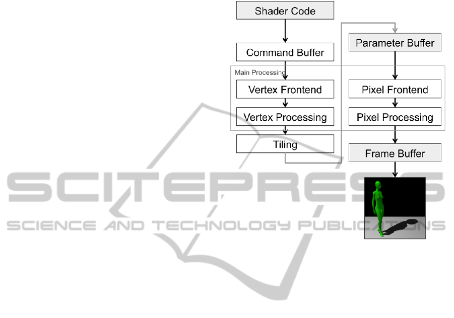
Figure 1 shows an overview of the hardware
pipeline in the PowerVR SGX chip (Smedberg,
2012). Vertex Data is taken from the Command
Buffer and distributed, via the Vertex Frontend,
among the GPU cores – each of which
independently processes its set of vertices according
to the Vertex Shader program. The results are then
optimized via the Tiler and stored in the Parameter
Buffer. The Pixel Front-end then fetches the output
from the Vertex program and passes it as input for
the Pixel program, which is again distributed among
the GPU cores, one whole tile at a time (i.e. tiles are
only processed in parallel on multicore GPUs). Non-
dependent texture reads are detected in the pre-
shader, before the main pixel shader calculations are
performed, and the texture reads are performed in
parallel. Once all the tiles have finished execution,
any required Multisample Anti-aliasing (MSAA) is
carried out, and the results written to framebuffer
RAM.
Figure 1: Overview of the graphics pipeline for the
PowerVR SGX chip.
After analysis of the structure of the pipeline, it is
possible to draw several conclusions that should
shape the design of any effective shadow-mapping
technique:
1. Changing render states (e.g. vertex input) causes
the shader to be recompiled by the driver, so it is
best to pre-compile a variety of shaders for each
object in the scene
2. Any calculation of texture coordinates in the
Pixel Shader reduces performance. As many
calculations as possible should be carried out in the
vertex shader to be stored in the Parameter Buffer.
3. Switching framebuffers is potentially expensive
as each render target is a whole new scene.
4. Dependent texture reads (where the location in
the texture must be calculated prior to reading its
value) should be minimised, especially given that
non-dependent texture reads can be performed in
parallel due to the action of the Pixel Frontend.
3 AN OVERVIEW OF SUITABLE
SOFT SHADOWING
TECHNIQUES
In this section we review a series of shadowing
GRAPP2014-InternationalConferenceonComputerGraphicsTheoryandApplications
182

techniques with regards to their suitability for
mobile hardware. A comprehensive literature review
of real-time shadowing is beyond the scope of this
paper, and the reader is directed to various reviews
(Hasenfratz et al. 2003; Bavoil 2008; Scherzer et al.
2011) and books (Eisemann et al. 2011; Woo &
Poulin 2012). Nevertheless, it is convenient to
summarise the basic technique and several
approaches that are suitable for potential
implementation on mobile hardware.
3.1 Basic Hard Shadowing
Shadow mapping was first proposed by Williams in
1978 (Williams, 1978) (differing from shadow
volumes proposed a year earlier (Crow, 1977)), and
the majority of research since that time has focused
on improving the appearance and speed of the basic
shadow mapping technique. Its underlying concept
is to pre-measure the distance from the object to a
light (distobj). When the scene is later rendered to
the screen (from the camera’s perspective), the
distance-to-light of each fragment is measured
(distfrag) and the fragment’s 3D position is re-
projected according to the light’s perspective in
order to recover distobj. If distfrag is greater that
distobj, we know that the object is closer to the light
than the current fragment, and that both positions lie
on the same projection from the light. Thus, the
current fragment is hidden from the light occluded
by the object, and its colour can be modified to make
it appear shadowed.
To implement the basic shadow-mapping
algorithm, the usual approach is to make a first
render pass from the light’s point of view, storing
the depth value of the resulting image as a texture,
termed the shadow map. This is then passed as a
parameter to the second render pass, this time from
the camera’s point of view. The light’s projection
matrices calculate each fragment’s position in the
shadow map, and a texture lookup is done to
calculate the distance to the light. The algorithm
suffers from several problems (e.g. shadow acne,
self-shadowing, shadow map resolution issues)
which must be overcome by introducing external
correction factors (Bavoil, 2008; Sander et al.,
2005).
Hard-shadowing is named so as it creates a
binary classification – each pixel is either occluded
(shadowed) or not. Thus, a characteristic result of
the technique is a jagged, pixelated shadow
boundary, with no smooth variation in shadow
intensity.
3.2 Soft Shadowing
The penumbra, as mentioned above, is the partially
shadowed area that is located at the edge of the
umbra (or hard shadowed area). In 1987, (Reeves et
al., 1987) proposed Percentage Closer Filtering
(PCF). Where simple shadow mapping compares a
single light-depth sample to the depth of the camera
sample, PCF performs several such evaluations in a
small window, or kernel. By averaging the
contribution of the entire kernel to the shadow value
of the central point, it is possible to draw pixels that
appear as partially shadowed (i.e. in penumbra) and
remove the binary appearance of the basic shadow
map technique. PCF has two key parameters:
i) the number of samples in the kernel (typically a
square, and varying from 2x2 up to, for example,
17x17)
ii) the ‘spread’, or distance in between each sample
in the kernel.
If the first parameter grows, the penumbra is
wider, at the cost of hugely increasing the number of
texture reads. The second parameter is commonly
set to the width of a single pixel in the shadow-map
texture; increasing it also widens the penumbra, but
can lead to aliasing effects within the penumbra. To
counteract these effects, the kernel can be
randomized and effectively transformed into a
sample disk (Engel, 2004) which converts the
aliasing effects into a Poisson distribution of noise,
in a disk with the radius of the width of the kernel.
Variance Shadow Mapping (Lauritzen, 2007) is
another soft shadowing technique with fixed
penumbra size. It calculates the variance of the
distribution of shaded pixels, and uses this to
calculate the probability of whether a pixel is in
shadow or not. Its advantage is that the results can
be easily filtered in hardware (for example using
mip-maps) thus relieving the pixel shader of the
requirement to execute any filtering calculations (as
with PCF). Its primary disadvantage is that it is quite
sensitive to the setting of parameters, to the bit-depth
of textures used in its calculation, and to light-
bleeding artefacts (Bavoil, 2008). Other fixed
penumbra solutions include Convolution Shadow
Maps (Annen et al., 2007) and Exponential Shadow
Maps (Annen et al., 2008).
The major disadvantages of fixed-penumbra
methods for shadow filtering are that they do not
attempt to model the real appearance of the
penumbra. The width of the penumbra is not
constant, and can depend on several factors, such as
the width of the light, and the distance between the
occluding surface and receiving surface. Fernando
VariablePenumbraSoftShadowsforMobileDevices
183

(Fernando, 2005) proposed Percentage Closer Soft-
Shadows (PCSS), which computes the filter
sampling range (in other words, the width of the
penumbra) adaptively, based on the relative
distances between the light source, occluder and
receiving surface. The filter radius is first
determined by point-sampling the depth map for
occluding surfaces, and then standard PCF can be
used with the deduced filter radius. In practice, a
blocker search radius of 5x5 pixels is sufficient for
shadowing without artefacts (Bavoil, 2008).
Another method of varying the penumbra size,
first introduced by Wyman and Hanson (Wyman &
Hansen, 2003), is to use an intermediate step to
create a separate image representing a ‘penumbra
map’. The underlying concept is to pre-process the
shadow map in order to create a separate input
texture for the final renderer, which describes the
extent of the penumbra at each point. The technique
was improved by (Chan & Durand, 2003) by
extruding degenerate quads from silhouette edges
(‘Smoothies’); and also by (Arvo et al., 2004), using
image space flood-fill techniques and multiple
rendering passes to obtain a penumbra map. (Lili et
al. 2010) propose another solution for the creation of
a penumbra-map by pre-processing the shadow map
using a simple Laplacian edge detector, and
interpolating the edge over the variable width of the
penumbra. For each pixel detected as edge, the
width of the penumbra is calculated using a very
similar equation to the PCSS technique. The
penumbra map is then calculated by interpolation of
the edge over the calculated width of the Penumbra
at that point. Drawing the shadow in the final render
is calculated by multiplying the value of the
penumbra map with the outcome of the standard
hard-shading technique.
4 CASE STUDY
4.1 Test Environment
For this study, a simple 3D scene renderer was
developed for Apple iOS in native Objective-C, C++
and Open GL ES 2.0. The purpose of the test
environment was to provide consistent conditions
for the testing of shadowing algorithms on the
PowerVR SGX GPU. As discussed in section 2
above, the rendering pipeline of this chip is typical
of that found in other mobile chips, including those
on other tablets and mobile devices running other
operating systems such as Android. The scene
contained two 3D mesh objects: a >50,000 vertex
mannequin model acting as the occluder, and a
simple floor plane to receive shadows. Self
shadowing of the occluder was disabled in
accordance with current industry practice
(Smedberg, 2012). The shadow-map resolution was
set to 1024x1024 pixels, except when tests were
carried out to determine the effect of changing this
resolution (see below). A perspective projection was
used for the creation of the shadow-map – despite
the fact that an orthographic projection is easier to
manipulate and could potentially provide better
results (Smedberg, 2012), as it provides less realistic
results with low, parallel light, where benefits of a
variable penumbra algorithm are best seen.
4.2 Initial Tests
Our initial baseline tests focused on implementing
soft-shadowing using PCF. The results were
disappointing. Adding a simple 4x4 PCF kernel to
the pixel shader caused the framerate to drop to 7fps.
One straightforward potential optimisation is to
calculate the texture coordinates in the vertex
shader, and pass them as varying data to the pixel
shader. This would enable the GPU’s Pixel Frontend
to queue texture look-ups in advance, and improve
performance. However the weakness of pixel
processing in such mobile architecture in general
means that many calculations (for example, for
lighting) are also preferably carried out in the vertex
shader, and must be passed onwards to the pixel
shader. Given that there is a hardware limit on the
chip of 32 float values that can be passed as varying
variables, a small 4x4 kernel uses half of the
available values, and is not practical for most uses.
Thus, this optimisation was discarded at an early
stage.
An implementation of the Variance Shadow
Mapping (VSM) (Lauritzen, 2007) algorithm
produced higher framerates, but a lack of available
bit-depth in the texture formats for OpenGL
textures in OpenGL ES 2.0 for iOS meant that VSM
produced too many rendering artefacts to be useful,
particularly in areas where the occluder was close to
the shading surface. In summary, our initial tests
showed that that neither unoptimized PCF nor VSM
are suitable for producing suitable shadowing for the
current generation of mobile graphics hardware.
4.3 Limiting Soft Shadowing with Edge
Detection
Based on the results of the initial tests, we
implemented a simple 5-sample edge detection
GRAPP2014-InternationalConferenceonComputerGraphicsTheoryandApplications
184
convolution filter (1) on the shadow map. Such a
simple filter was chosen in order to minimize the
required texture lookup on the GPU, (although the
effect of using more complex filters is discussed
below). As recommended in Section 2, these texture
coordinates are calculated in the Vertex Shader.
010
141
010
(1)
A mip-chain dilation, similar to as proposed by
(Sander et al., 2005), was used to dilate the
discovered edge. The dilation samples lower-level
mip-map images at the native resolution, and
implements a clamp function where any input value
> 0.0 is clamped to 1.0. Bilinear filtering is used in
mip-chain creation in order to reduce aliasing issues.
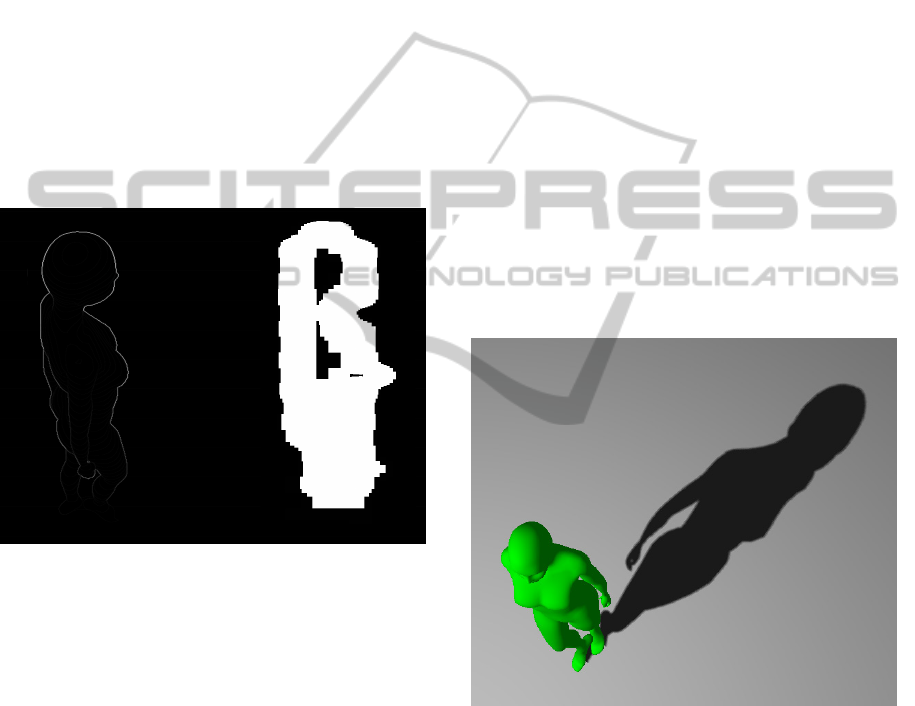
This provides us with a ‘shadow mask’ texture as
shown in the Figure 2.
Figure 2: Results of edge detection filter on shadow map
(left) and resulting mip-chain dilation (right).
By sampling this dilated edge image as mask texture
in our main shader, we can selectively apply soft
shadowing in the main scene render. In pixels where
sampled value of shadow mask is 0.0, we apply
standard hard shadowing – thus pixels in the umbra,
and outside the entire shadow, and tested using
simple hard shadowing. Where the sampled value of
the shadow mask is 0.0, for this pixel we apply a
PCF kernel, using poisson-distributed sampling to
reduce banding (Engel, 2004).
Using this method, we see the framerate jump
from 7fps to 25fps, using a 4x4 PCF kernel. This,
then, demonstrates that it is possible to execute soft
shadowing on mobile chipsets with reasonable
performance (see Figure 3).
4.4 Variable Soft Shadowing
As explained by (Fernando, 2005) and elsewhere,
the greater the distance between the occluder and
shadowed surface, the wider the penumbra should
be. With this in mind, our goal was to create an
efficient implementation variable penumbra soft
shadowing, usable on mobile devices. With concerns
about the possible performance hit of the blocker-
search phase of PCSS, and following the existing
results using edge-detection, we modified our clamp
function of the mip-chain dilation step to quantize
the detected edge into discrete bands. The edge
detection convolution filter of (1) by its nature
produces a stronger edge (higher pixel value) in
areas where the occluder is further from the
background. In areas where the occluder is near the
background, the edge will be very weak; thus this
intensity information can be used to simulate the
widening the of penumbra where the occluder-
background distance is larger. Note that this
approach is similar in certain aspects to the Min-
Max mip-map shadow-map approach of (Dmitriev
& Uralsky, 2007).
Figure 3: 4x4 PCF.
We decided to quantize the edge intensity because
the PCF kernel is, by its nature, discrete: a 3x3
kernel can only be enlarged in discrete units (to 4x4,
5x5 etc.). However, the mip-chain dilation
algorithm, again according to its nature, loses the
strength of the detected edge, as the required
thresholding step permanently clamps intensity to
1.0. Our solution is to take advantage of the different
colour channels of GL_RGBA texture. For edge
intensity d in the initial edge detection texture:
VariablePenumbraSoftShadowsforMobileDevices
185
0.2 < d ≤ 0.5 : blue channel
0.5 < d ≤ 0.8 : green channel
0.8 < d : red channel
The thresholding step of the mip-chain dilation
algorithm now preserves these three discrete levels
(in effect, four levels, as the absence of an edge
provides data also) and therefore information about
edge intensity, and thus the distance between
occluder and shading surface can be preserved. By
testing for these discrete levels in the final render,
we can now selectively apply different PCF kernel
sizes to achieve the desired penumbra width. Where
we detect a larger distance between occluder and
surface, we use a larger PCF kernel to obtain a wider
penumbra. Where the occluder distance is lower, we
apply a smaller PCF kernel (or even use hard
shadowing) to obtain a narrow penumbra.
With this approach, our test scene demonstrated
variable penumbra shadow mapping, with penumbra
width increasing with occluder distance, running at
20fps.
4.4.1 Visual Results
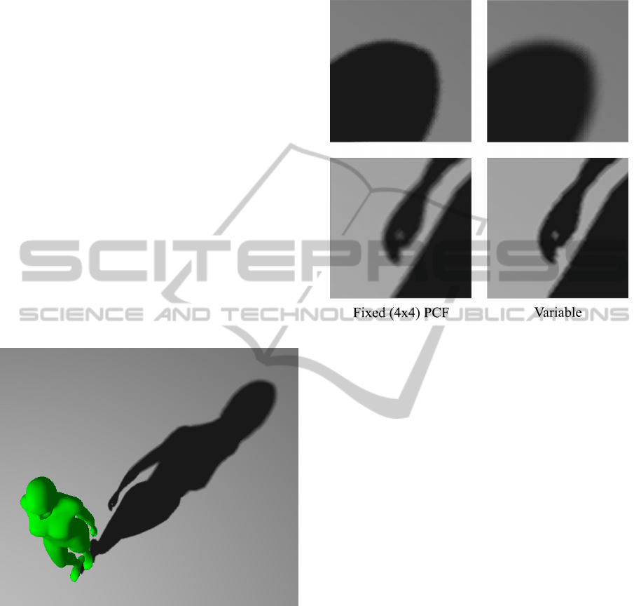
Figure 4: Variable Penumbra soft-shadows.
Figure 4 shows an image of the test scene with the
variable penumbra soft shadows. Figure 5 shows a
zoom comparison of the differences between fixed
(PCF) and variable penumbra. In regions where the
occluder is far, the variable penumbra is softer than
the fixed penumbra. In regions where the occluder is
near, the variable penumbra shadow is harder than
the fixed penumbra. For this figure, the kernel
widths within the three quantized levels were set to
3x3, 5x5 and 7x7 samples, whereas the fixed
penumbra was set to a 4x4 kernel. The variable
images (right column) show a wider penumbra in the
head region (far occluder) yet greater detail
maintained in the hand (near occluder).
Figure 5: Zoom comparison image of two regions of
shadow. Top row: far occluder. Bottom row: near
occluder. Left column: Fixed (4x4 PCF) penumbra. Right
column: variable penumbra.
4.4.2 Artefacts and Corrective Measures
Although in many cases the variable penumbra
algorithm proposed produces good results, there are
occasionally shadowing artefacts where an incorrect
filter width is applied in a small region. These errors
can be linked directly to the quality of the detected
edge of the shadow map. Irregularities in the
detected edge are caused either by incorrect edges
being detected within the model geometry, or noise
due to the use of such a simple filter at low image
resolution. Any irregularities affect the quantization
which leads the areas affected being shadowed using
a different filter width to their surrounding area.
Increasing the resolution of the shadow-map,
and/or using a more accurate edge-detection filter
can correct these artefacts, as both approaches
improve the quality and remove noise from the
detected edge. Nonetheless, this correction comes at
the cost of rendering speed and framerate, as shown
in the results below. The artefacts due to internal
object edges are more serious and more difficult to
overcome. If an internal object boundary (for
example from an arm overlapping the body) is near
the external boundary of the edge (when seen from
the light perspective) there is a risk that the latter
(which is what our proposed variable penumbra
GRAPP2014-InternationalConferenceonComputerGraphicsTheoryandApplications
186

technique depends on) will be masked by the
internal edge formed by object self-occlusion. This,
in turn, will lead to incorrect classification of
occluder distance in that region of the image.
A final unavoidable issue, common to every
technique employing variable PCF kernels, is the
potential for a visible ‘jump’ on the shadow
boundary when changing between kernel widths.
This can be minimised by ensuring the difference
between kernel widths is kept low.
4.5 Comparison of Results
Table 1: Comparison of framerates obtained using the test
scene and hardware. The iPad is hardware limited to
60fps.
Shadow Technique Framerate
Hard Shadowing 52fps
4x4 Standard PCF 7fps
4x4 PCF
w/ Shadow Mask
25fps
7x7 PCF
w/ Shadow Mask
11fps
Quantized Shadow Mask –
2x2, 3x3, 5x5
20fps
Quantized Shadow Mask
– 3x3, 5x5, 7x7
14fps
Table 1 summarises the framerates obtained during
the case study presented in this paper. It is important
to note that, as shadow mapping is a pixel-based
method, the larger the shadow on the screen, the
lower the performance – changing the light and
camera position can produce very different results.
The scene used for all of these results was kept
static, thus it is the difference between the obtained
framerates that allows us to compare each method.
The table shows clear improvement in framerate
when using a Shadow Mask to restrict PCF
application, and only small degradation when using
a quantized Shadow Mask to apply variable PCF
filter kernels within the scene. As expected, the
performance degrades when the kernel sizes of each
level are increased. Table 2 briefly summarises the
differences in performance when changing the
shadow map resolution. The performance degrades
notably with increasing resolution, yet the improved
performance of using a 512x512 pixel shadow-map
is offset by poor visual results, due to the appearance
of artefacts, as mentioned above. Using a more
accurate edge detector, for example a kernel filter
such as in equation (2), improves the results
marginally, but does not satisfactorily remove
artefacts from the 512x512 shadow-map image.
Table 3 shows the performance hit when using the
filter from (2), which is due to 9 texture look-ups
being performed per pixel instead of the required
five in (1).
1 1 1
181
1 1 1
(2)
Table 2: Effect of changing shadow-map resolution on a
Quantized Shadow Mask (2x2, 3x3, 5x5).
Resolution (pixels) Framerate
512x512 24fps
1024x1024 20fps
2048x2048 12fps
Table 3: Effect of using a more accurate convolution filter
- Quantized Shadow Mask (2x2, 3x3, 5x5); 1024x1024.
Resolution (pixels) Framerate
Filter from (1) 20fps
Filter from (2) 14fps
5 SUMMARY
AND CONCLUSIONS
The principal results of this paper can be
summarised in three points, which together comprise
the contribution of the paper to the graphics
community:
The current generation of mobile hardware is not
capable of painting un-optimized PCF soft-
shadows with acceptable performance;
Edge-detection and mip-chain dilation can increase
the performance of PCF on mobile hardware to
acceptable levels;
The technique used to perform this optimisation
can be extended to create variable Penumbra
shadowing, with only small performance loss;
Our future work has three main foci: the first is
to address the issue of artefacts due to occluding
edges. One possible approach to solve this would be
to use a Z-peeling approach to store the depths of all
light occluders for a given pixel; and use this
information to draw the edge. The second focus is to
apply more rigorous testing of our techniques on
different hardware; while we can naturally
extrapolate performance for GPUs from the same
family (such as in other iPad or iPhone models),
current performance on other chips with different
operating systems (such as Android) is not known.
Our final focus is to engage more critical
comparison with established shadow-mapping
techniques, especially variable penumbra methods
VariablePenumbraSoftShadowsforMobileDevices
187

such as PCSS, and also make more extensive tests
with more demanding scenes, involving large scale
geometry and multiple meshes.
ACKNOWLEDGEMENTS
This work was funded by the IMPART FP7 project
http://impart.upf.edu/
REFERENCES
Annen, T., Mertens, T. & Bekaert, P., 2007. Convolution
shadow maps. In Proceedings of the 18th
Eurographics conference on Rendering Techniques.
pp. 51–60.
Annen, T., Mertens, T. & Seidel, H., 2008. Exponential
shadow maps. Proceedings of graphics interface 2008,
pp.155–161.
Arvo, J., Hirvikorpi, M. & Tyystjarvi, J., 2004.
Approximate Soft Shadows win an Image-Space
Flood-Fill Algorithm. Computer Graphics Forum,
23(3), pp.271–279.
Bavoil, L., 2008. Advanced soft shadow mapping
techniques. In Presentation at the game developers
conference GDC08.
Chan, E. & Durand, F., 2003. Rendering fake soft
shadows with smoothies. Proceedings of the 14th
Eurographics workshop on rendering, pp.208–218.
Crow, F. C., 1977. Shadow algorithms for computer
graphics. ACM SIGGRAPH Computer Graphics,
11(2), pp.242–248.
Dmitriev, K. & Uralsky, Y., 2007. Soft shadows using
hierarchical min-max shadow maps. In Presentation at
the game developers conference GDC07.
Eisemann, E. et al., 2011. Real-Time Shadows, A K
Peters/CRC Press.
Engel, W., 2004. ShaderX3: Advanced Rendering with
DirectX and OpenGL (Shaderx Series), Charles River
Media.
Fernando, R., 2005. Percentage-closer soft shadows. In
ACM SIGGRAPH 2005 Sketches on -
SIGGRAPH ’05. New York, New York, USA: ACM
Press, p. 35.
Hasenfratz, J.-M. et al., 2003. A Survey of Real-time Soft
Shadows Algorithms. Computer Graphics Forum,
22(4), pp.753–774.
Lauritzen, A., 2007. Summed-Area Variance Shadow
Maps. In GPU Gems 3.
Lili, W., Jingchao, Z. & Zhe, S., 2010. Real-Time
approximate soft shadow rendering with bidirectional
penumbra map. In 2010 International Conference on
Educational and Information Technology. IEEE, pp.
1338–43.
Mamassian, P., Knill, D. C. & Kersten, D., 1998. The
perception of cast shadows. Trends in Cognitive
Sciences, 2(8), pp.288–295.
Reeves, W. T., Salesin, D. H. & Cook, R. L., 1987.
Rendering antialiased shadows with depth maps. ACM
SIGGRAPH Computer Graphics, 21(4), pp.283–291.
Sander, P et al., 2005. Computation Culling with Explicit
Early-Z and Dynamic Flow Control. In In GPU
Shading and Rendering. ACM SIGGRAPH Course 37
Notes.
Scherzer, D., Wimmer, M. & Purgathofer, W., 2011. A
Survey of Real-Time Hard Shadow Mapping Methods.
Computer Graphics Forum, 30(1), pp.169–186.
Smedberg, N., 2012. Bringing AAA graphics to mobile
platforms. In Presentation at the game developers
conference GDC12.
Williams, L., 1978. Casting curved shadows on curved
surfaces. ACM SIGGRAPH Computer Graphics,
12(3), pp.270–274.
Woo, A. & Poulin, P., 2012. Shadow Algorithms Data
Miner, A K Peters/CRC Press.
Wyman, C. & Hansen, C., 2003. Penumbra maps:
approximate soft shadows in real-time. In Proceeding
EGRW ’03 Proceedings of the 14th Eurographics
workshop on Rendering. Eurographics Association,
pp. 202–207.
GRAPP2014-InternationalConferenceonComputerGraphicsTheoryandApplications
188
