
Towards a Natural Interaction for Rapid Prototyping of Parametric
Closets
Iv
´
an Rodr
´
ıguez
1
, Celso Campos
1
, Enrique Barreiro
1
, Jorge V
´
azquez
2
and Roc
´
ıo Veiga
2
1
Department of Computer Science, University of Vigo, Campus As Lagoas 32004, Ourense, Spain
2
Redegal S.L., Avda. de la Habana, 43 1
o
Izda. 32004, Ourense, Spain
Keywords:
Procedural Modelling, CAD, Multi-touch Devices, Natural Interaction, Rapid Prototyping, Closets.
Abstract:
Custom closets customers usually lack the expertise to design their desired closet. The use of a software tool
that incorporates the design expertise might allow them to sketch their ideas without third party oversight.
While architecture related applications are very powerful and make it possible to have an accurate graphical
representation of real world, these Computer-Aided Design (CAD) tools demand high technical training and
their use in the engineering field is generic. Our work, framed within the development of a rapid prototyping
tool of custom closets called Sketch Arm, introduces an interaction proposal that seeks to minimize the time
and complexity associated with typical operations in CAD. Supported by multi-touch capabilities of today’s
mobile devices, our system allows users to manipulate the closet structure directly in real time by using a
minimalist graphical user interface (GUI) together with a touch interface based on easily recognizable gesture
patterns. Direct on-screen data manipulation is very attractive to the end-user in general and highly beneficial
for novice IT users in particular while gesture-based interaction is extremely intuitive for performing artistic
tasks. Throughout the article, we will describe in depth the designed interaction system and we will present
the original solutions we made to common problems in touch systems like accuracy and occlusion.
1 INTRODUCTION
Custom closets manufacturing arises in response to
the spatial limitations that nowadays many of the ex-
isting housing present, improving the organization
and use of available space in living quarters.
The customer usually lacks the expertise to deal
with the design process independently and is assisted
by the manufacturer for the creation of an initial pro-
totype together. This model is time consuming and
involves a significant increase in the final manufactur-
ing cost. The use of a software tool that incorporates
the design expertise, will allow the user to sketch his
ideas without third party oversight.
To that end, there are many computer applications
that facilitate the design process, enabling us to obtain
a graphical representation of the real world. These
Computer-Aided Design (CAD) tools, although very
powerful, demand high technical training and their
use in the engineering field is generic.
To address those issues, we have developed a rapid
prototyping application for designing custom closets,
named Sketch Arm. The main purpose of the system
is to facilitate the operations involved in the creative
process. We propose a direct interaction system that,
supported by multi-touch capabilities of current mo-
bile devices, allows the user to manipulate the closet
structure in real time, combining the use of a com-
mon graphical user interface (GUI) with the use of a
gesture-based natural interface.
Touching and manipulating data directly on the
screen, without using any additional input device, is
very attractive to the end-user: this direct manipu-
lation style mainly benefits novice IT users (Albins-
son and Zhai, 2003; Benko et al., 2006) thanks to a
gentle learning curve. For its part, gestured-based in-
teraction is an extremely intuitive interface —as it is
based on inherent human capabilities— for handling
applications that involve any artistic work. However,
the mere incorporation of both interaction methods to
human-machine communication process does not en-
sure end-user satisfaction. We must design a global
interaction in which each element has a purpose and
brings added value to user experience.
According to the established goal, we organize
the rest of the paper as follows. The second sec-
tion presents a brief summary of several supporting
works and techniques. Then, we provide an overview
409
Rodríguez I., Campos C., Barreiro E., Vázquez J. and Veiga R..
Towards a Natural Interaction for Rapid Prototyping of Parametric Closets.
DOI: 10.5220/0004633104090416
In Proceedings of the 9th International Conference on Computer Graphics Theory and Applications (GRAPP-2014), pages 409-416
ISBN: 978-989-758-002-4
Copyright
c
2014 SCITEPRESS (Science and Technology Publications, Lda.)

of Sketch Arm in order to put our work in context.
The remaining two sections are focused on the user-
system interaction: the fourth one provides a brief
description of the different stages in the interactive
closet design process, and the next one describes in
more detail the various elements of the interaction
system proposed to support design tasks. Finally, we
present the most significant conclusions of our work
and we identify future lines of action.
2 BACKGROUND
Multi-touch technology has been extensive studied in
the past 20 years, in which many authors have focused
their efforts, among other things, on (i) reducing the
manufacturing cost of the supporting hardware (Han,
2005), (ii) enhancing its portability (Pinhanez et al.,
2003) and sensitivity (Dietz and Leigh, 2001; Reki-
moto, 2002), and (iii) developing software systems
based on this new interface.
With regard to the last point, there are already sev-
eral works in the literature that, instead of creating
these systems as mere testbeds for the design of a new
interaction proposal, seek to develop really useful
tools. As an example, we can mention applications for
purposes as diverse as medical imaging (Lundstrom
et al., 2011), sketch design (Bae et al., 2008) and
animation (Quevedo-Fern
´
andez and Martens, 2012),
or information visualization in museums (Hornecker,
2008).
However, almost all of these applications are
aimed to casual users —users with low IT skills—
and its exploitation in professional contexts is usually
neglected. In this sense, it would be interesting to
examine to what extent this interaction may allow us
to simplify the use of professional tools —eminently
complex—, either to enable expert users to carry out
their work expeditiously or to bring its use closer to
novice users.
To that end, our paper presents a novel and attrac-
tive interaction proposal which minimizes the time
and complexity normally associated with typical op-
erations in CAD environments, within the profes-
sional context of furniture industry. While direct-
touch interaction provides a greater interactive rich-
ness than traditional WIMP (Windows, Icons, Menus,
Pointer) systems, the implementation of this touch-
based interaction for common CAD tasks is not triv-
ial. Among these tasks, the selection operation —
highly performed in this kind of tools— is especially
problematic. Specifically, the two main problems tra-
ditionally associated with using the finger as a point-
ing and selection tool are accuracy and occlusion.
Multiple authors have sought to determine the
ideal size of GUI widgets in order to minimize the
accuracy problem. Thus, Hall et al. point out in their
1988 study (Hall et al., 1988) that this accuracy can
be 99.2% for targets with a size of 26 mm. Subse-
quently, however, A. Sears and B. Schneiderman note
in his work (Sears and Shneiderman, 1991) that ac-
curacy is maximized when the target has a size of 32
pixels —13.8 mm x 17.9 mm—. This study still holds
true, being borned by different recent papers (Dan-
dekar et al., 2003; Wang and Ren, 2009).
There are several additional approaches in the lit-
erature that have also attempted to solve the accuracy
problem in traditional touch systems by (i) using a
wider selection area or hot spot instead of the mouse
cursor (Kabbash and Buxton, 1995), (ii) using both
selection methods (Worden et al., 1997), or (iii) using
resizable widgets (Bederson, 2000), that can dynam-
ically change their size in order to provide a larger
interaction area to users.
For their part, in relation to the occlusion problem,
some authors have primarily focused their efforts on
preventing the user from hiding the on-screen cursor
with his fingers. The methods proposed to achieve
this, range from applying a small offset above the
user’s fingertip —fixed in Take Off, a technique in-
troduced by Potter et al. in (Potter et al., 1988), and
dynamic in the case of the technique named Dual Fin-
ger Offset, introduced by Benko et al. in (Benko et al.,
2006)— to the cursor, to the use of an on-screen call-
out for displaying a copy of the occluded screen area
(Vogel and Baudisch, 2007).
3 SKETCH ARM. SYSTEM
OVERVIEW
Sketch Arm is organized into three distinct but closely
related subsystems: (A) interactive sketching subsys-
tem, (B) automatic design generation subsystem and
(C) resulting model rendering subsystem. The first
two subsystems are responsible for generating the 3D
geometric information that represents the closet. The
third one is responsible for providing a visual repre-
sentation of the closet, created from that information,
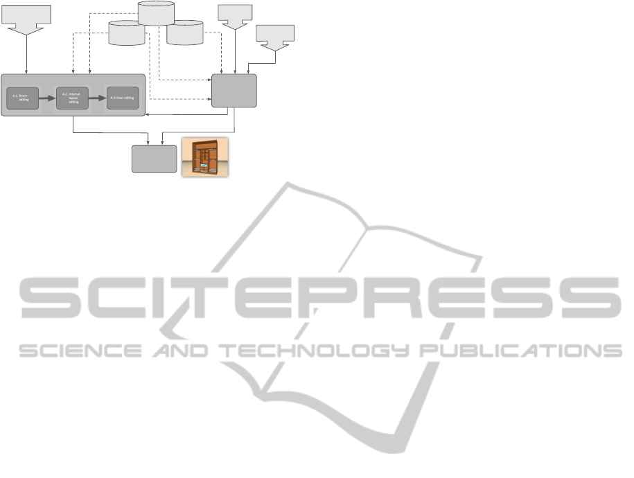
as the final output of the entire system. Figure 1 shows
a diagram of the overall architecture of Sketch Arm.
As shown in Figure 1, subsystems A and B receive
information from existing knowledge bases and data
obtained from user interaction as input, and they both
provide as output a geometric model that character-
izes the closet structure. However, both subsystems
deal with the creation of the model by significantly
different strategies:
GRAPP2014-InternationalConferenceonComputerGraphicsTheoryandApplications
410
!""#$$%&' #$
!()'* +#&!"+', #)$- #+" .'* /)$01$2$+# 3
&445
6789:;
!(<(
=44>)6789:;
!(?(
':@6>:AB)
BAC4D@
6789:;
!(E(
!0+% 3!+'")
/#* #&!+' %*)
$01 $2$+ #3
1(
=#$'/*)
"%* $+& !'* +$
$'F #)
"%* $+& !'* +$
?=)&#*= #&' */)
$01 $2$+ #3
"(
0$# &G+%0".)$0& H!"#)
'*+ #&! "+'%*)=!+!
"I%$#+)
='3 #*$ '%*$
!3% 0*+ )%H)
"I%+ .#$)+%)1#)
$+%& #=
?=);6456@>8J)8:K4>5A94:)4K)@L6)JB4M6@
?=);6456@>8J)8:K4>5A94:)4K)@L6)JB4M6@
?=);6456@>8J)8:K4>5A94:)4K)@L6)JB4M6@
"45NA>@56:@M)
5A@JL8:;
':7DM@>C)M@A:7A>7)M8O6
':7DM@>C)M@A:7A>7)M8O6
/6456@>8J)
8:K4>5A94:)4K)@L6)
AJJ6MM4>86M
$@A:7A>7)M8O6)4K)AJJ6MM4>86M
"45NA>@56:@GAJJ6MM4>C)5A@JL8:;
Figure 1: Overall architecture of Sketch Arm.
• The interactive editing subsystem takes as input
data collected from the interaction between the
user and the multi-touch surface of the supporting
hardware device. This subsystem is intended to
allow the end-user to emulate the creative process
undertaken by professional designers and it pro-
vides him with the necessary tools to create and
customize in real time the various constituent ele-
ments of the closet.
• The automatic generation subsystem demands al-
most no user intervention: the individual must
provide only the dimensions of the closet and the
amount of clothing he wants to store in percent-
age terms. This subsystem is able to generate
autonomously different design proposals to meet
both users’ storage needs and, as far as possible,
the design and dimensional constraints contained
in the system. The paper (Rodr
´
ıguez et al., 2013)
provides a detailed description of this subsystem
and the configuration of the proposed stochastic
optimization algorithm for the automatic layout
generation.
In the rest of the paper we will focus on the in-
teractive editing subsystem. We will present the dif-
ferent tasks involved in the prototyping process and
describe in more detail the interaction system we de-
signed to support them.
4 DESIGN FLOW IN THE
INTERACTIVE EDITING
PROCESS
The design process consists of a set of operations for
the three-dimensional parametric modeling of clos-
ets. This process is broken down into three sequential
stages and each stage results in a functional module
that gathers the relevant operations. Thus, we have a
room editing module, an internal layout editing mod-
ule and a door editing module.
4.1 Room Editing Module
The primary aim of this module is to obtain a geomet-
ric model of the external structure of the closet from
a basic outline of the room. The user defines this out-
line by creating the walls and pillars that make up the
structural shape of the room. Then, the position, ori-
entation and size of the closet are directly calculated,
taking as a reference the geometry of the selected sup-
porting wall. To do this:
• The origin of the closet is translated to the position
of the origin point of the wall.
• The closet is rotated towards the direction of the
normal vector of the wall.
• The width and height of the closet are deter-
mined by the corresponding dimensions of the
wall. Depth, however, is constant and takes the
standard value in closet manufacturing industry.
4.2 Internal Layout Editing Module
The design is completed by incorporating additional
geometric elements to the basic model created in the
previous stage. These representative elements of the
internal structure of the closet include vertical and
horizontal dividing elements, and instantiable ele-
ments or accessories —bars, drawers, etc.—.
While the addition of an instantiable element is
just a simple assignment operation, introducing a di-
viding element is a complex process that causes the
segmentation of a compartment into two new child
compartments. This process involves the creation of
new structural elements and also the computation of
the transformation matrices needed to adjust each ele-
ment to the local system defined by the interior of the
parent compartment. Transformations are calculated,
therefore, from the scale, position and orientation of
this compartment.
4.3 Door Editing Module
Once the structure of the closet carcass has been de-
tailed, all that remains is to create the front doors.
This process involves three stages:
1. Constructing an initial basic geometric model for
each door.
2. Dividing each door into panels.
3. Configuring the visual appearance of each panel.
TowardsaNaturalInteractionforRapidPrototypingofParametricClosets
411
The construction of the initial model of the door is
automatic and completely transparent to the end-user:
the system is responsible for defining the geometry
of the model and computing the scale, translation and
rotation matrices for proper rendering. However, the
division stage demands user intervention like the edi-
tion of the internal layout of the closet, but it only al-
lows horizontal dividers. Finally, in the visual appear-
ance configuration stage the user can assign a material
or color to each created panel as a texture of its front
face.
5 INTERACTION SYSTEM
Sketch Arm interaction system rests on three major
guidelines or design principles:
1. A simpler GUI
2. A touch-based interface for the direct manipula-
tion of the elements in the design.
3. The minimization and simplification of mode
switching.
Throughout this section we will present in greater
detail the work we have carried out in relation to the
outlined design principles and the solutions we pro-
pose to different problems associated with using the
fingers for pointing and selecting.
5.1 Simplifying the GUI
The design of the graphical interface aims to give the
user an access as immediate as possible to system
functionality. We remove the superfluous elements of
the application to get a clean, clear and minimalist in-
terface that cedes part of its prominence to provide the
end-user with a seamless and superior experience.
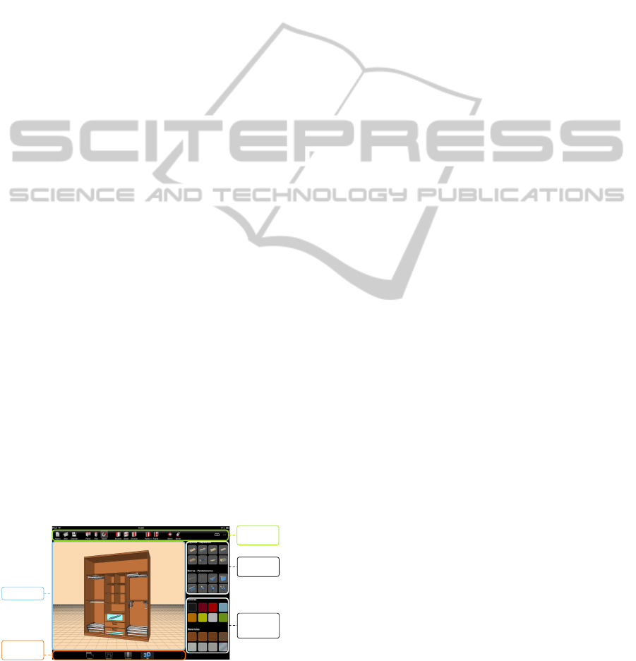
The tool is designed as a single landscape view
that includes all the graphical elements of the user in-
terface (Figure 2).
Drawing canvas
Navigation
bar
Toolbar
Accessories
Visual finishes for
door panels
Figure 2: Layout of Sketch Arm GUI.
These elements are displayed on screen according
to the usual layout of iOS Apps:
• The toolbar gives the user access to functionality
for creating and modifying the different compo-
nents of the closet.
• The drawing canvas is where the user performs
the tasks involved in the design process. Through
this central panel, the system gives constant feed-
back to the user, displaying in real time the design
resulted from each operation.
• On the right of the drawing canvas we include a
panel that provides direct access to both visual fin-
ishes for the different panels of the front doors and
accessories that can be included inside the com-
partments of the carcass.
• The navigation bar allows the user to toggle be-
tween the different views associated with each
functional module.
The design of the graphical elements must be aes-
thetically pleasing in order to create an engaging ex-
perience for the end-user. In touch systems it is
also necessary to focus efforts on appropriately sizing
these elements so as not to hinder the interaction. On
the basis of the works (Dandekar et al., 2003; Sears
and Shneiderman, 1991; Wang and Ren, 2009) re-
ferred in the state of the art, we adequate the GUI to
fit the touch interaction style by following the seen
dimensional guidelines. Thus, we set the toolbar but-
tons size to 40 pixels per side —14.1 x 14.1 mm—,
the right panel buttons size to 54 pixels per side —
19.1 x 19.1 mm—, and the width of the buttons on
the navigation bar to 76 pixels and its height to 44
pixels —26.8 x 15.5 mm—.
5.2 Touch-based Interface for the Direct
Manipulation of the Design
Elements
The interaction between the user and the application
is mainly channeled through the central drawing
canvas. We assume that the first finger that touches
the canvas, called primary finger, is the index finger
of the dominant hand. Any additional touch is
assigned to any other finger of either hand. We define
four action templates to support the tasks involved in
the design process: (i) single or multiple taps on any
GUI control, (ii) single tap on any design element
and then single tap on any GUI control, (iii) single
tap on any GUI control and then single tap on any
design element, and (iv) single tap on any design
element and drag.
i. Single or multiple taps on any GUI control. The
user taps with only one finger on a GUI control to
GRAPP2014-InternationalConferenceonComputerGraphicsTheoryandApplications
412
activate the corresponding tool and thus trigger the
actions associated with it. This template is reserved
for the use of certain functionalities —primarily to
create new objects in the scene— that are imple-
mented as automatisms and require no additional
user interaction to the simple activation of the tool.
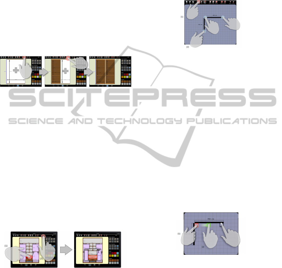
As seen in Figure 3, this action template is visible,
for example, when the user adds a new door to the
design: when the button is single tapped by an user,
the system performs the construction of the geometric
model of the new door autonomously.
Figure 3: Door creation process. Each single tap on the
associated button triggers the calculations needed to para-
metrically define a new door and change the position and
scale parameters of previously created doors.
ii. Single tap on any design element and then
single tap on any GUI control. Firstly, the user
single taps an object to select it. This way, the
individual intentionally points to the object on which
he wants to perform an operation. Then, the subject
uses his finger again to tap the button associated with
that operation to modify the selected object or as
reference for adding a new element to the design.
Thus, for example, to include a horizontal division
inside the closet, the user has to first select a target
compartment and then tap the shelves creation button.
As shown in Figure 4, this interaction template is
also evident in most of the editing operations, like the
deletion of an element.
Figure 4: Deletion of an object from the design.
iii. Single tap on any GUI control and then single
tap on any design element. There are some tools
that, once selected, require an extra touch on the
drawing canvas to create a new object at a specific
location in the scene. The user explicitly provides
the location by pointing his finger to a certain spot,
which is an eminently natural gesture. The system
translates the 2D coordinates of the touch event to
the position coordinates of the target location in the
3D Cartesian space. This template is visible, among
other tasks, in wall creation: the user first selects the
tool (Figure 5.1) and then creates the endpoints of the
walls with successive single taps (Figure 5.2).
Figure 5: Creation of the walls that make up the shape of
the room.
iv. Single tap on any design element and drag. Be-
yond specific object creation and deletion tools, there
are some other ones that must be included in any CAD
or rapid prototyping application. We are talking about
translation and scaling tools. These operations, as we
will see next, are closely related in our system.
To perform the translation of an object, the user
must first tap the object to select it (Figure 6.1) and
then, without lifting his finger from the touch surface,
drag it across the screen to the target position (Fig-
ure 6.2). The translation ends when the user lifts the
finger from the touchscreen (Figure 6.3).
As the user drags his finger across the drawing
canvas, the object slides in such a way that it re-
mains under the fingertip. This direct manipulation
provides the user with an engaging experience, since
the movement of the selected object thus conceived is
predictable and transmits to the user the sensation of
actually moving the object.
!"#
!$#
!%#
Figure 6: Translation of an object across the drawing can-
vas.
The translation of the object does not exclusively
affect its position. We implemented an algorithm
called indirect scaling that modifies the dimensions
of the sketch elements that have some connection or
relationship with the translated object. Thus, for ex-
ample, when the user moves a divisor, the system au-
tomatically resizes both adjacent compartments and
the accessories inside them.
Indirect scaling is significantly different from the
approach commonly used in traditional CAD tools in
which user must explicitly enter the dimensions for
TowardsaNaturalInteractionforRapidPrototypingofParametricClosets
413
each object by using a physical keyboard. The main
alternative to physical keyboard in touch interfaces is
the use of an on-screen keyboard, widely reviewed
in the literature (Zhai et al., 2000) and extensively
implemented in recent multi-touch mobile devices.
Nevertheless, we reject the use of the touch keyboard
due to its ergonomic and feedback problems (Lewis
et al., 1997) that adversely affect the end-user’s per-
formance and comfort.
Our scaling mechanism enables an efficient ob-
ject sizing in touch-based systems but it is inherently
less accurate than directly typing the different values
with a physical keyboard. To improve this, we im-
plemented a non-intrusive accuracy mechanism. The
user can naturally activate the accuracy mode while he
is sliding an object across the drawing canvas. To do
this, the user must keep the fingertip still on the object
for 1000 ms. Thereafter, a smaller scale is applied to
any object translation, thus increasing the movement
accuracy. The user ends this mode by tapping any-
where in the canvas except on the object itself.
5.3 Scene Elements Selection
Mechanism
The introduced action templates largely rely on first
selecting an element of the sketch. This is common to
many typical CAD tasks, which also require the selec-
tion of a specific object or entity to trigger a particular
process.
While in desktop CAD tools the individual uses
the mouse cursor, Sketch Arm’s touch nature and the
consequent absence of the on-screen pointer force the
individual to use his finger as a pointing and selecting
device, causing accuracy and occlusion problems. To
solve both problems, we have implemented a number
of specific mechanisms that seek to address them
from different angles.
Additional viewport for displaying relevant infor-
mation. Inspired by the Shift technique, introduced
by Vogel and Baudisch (Vogel and Baudisch, 2007),
our method also consists in including a small on-
screen additional viewport when one finger taps the
touch surface. This feature is only enabled for cer-
tain operations that demand high accuracy. However,
unlike Shift, the viewport does not display a copy of
the area occluded by the finger; it provides text in-
formation that is relevant in the operation context and
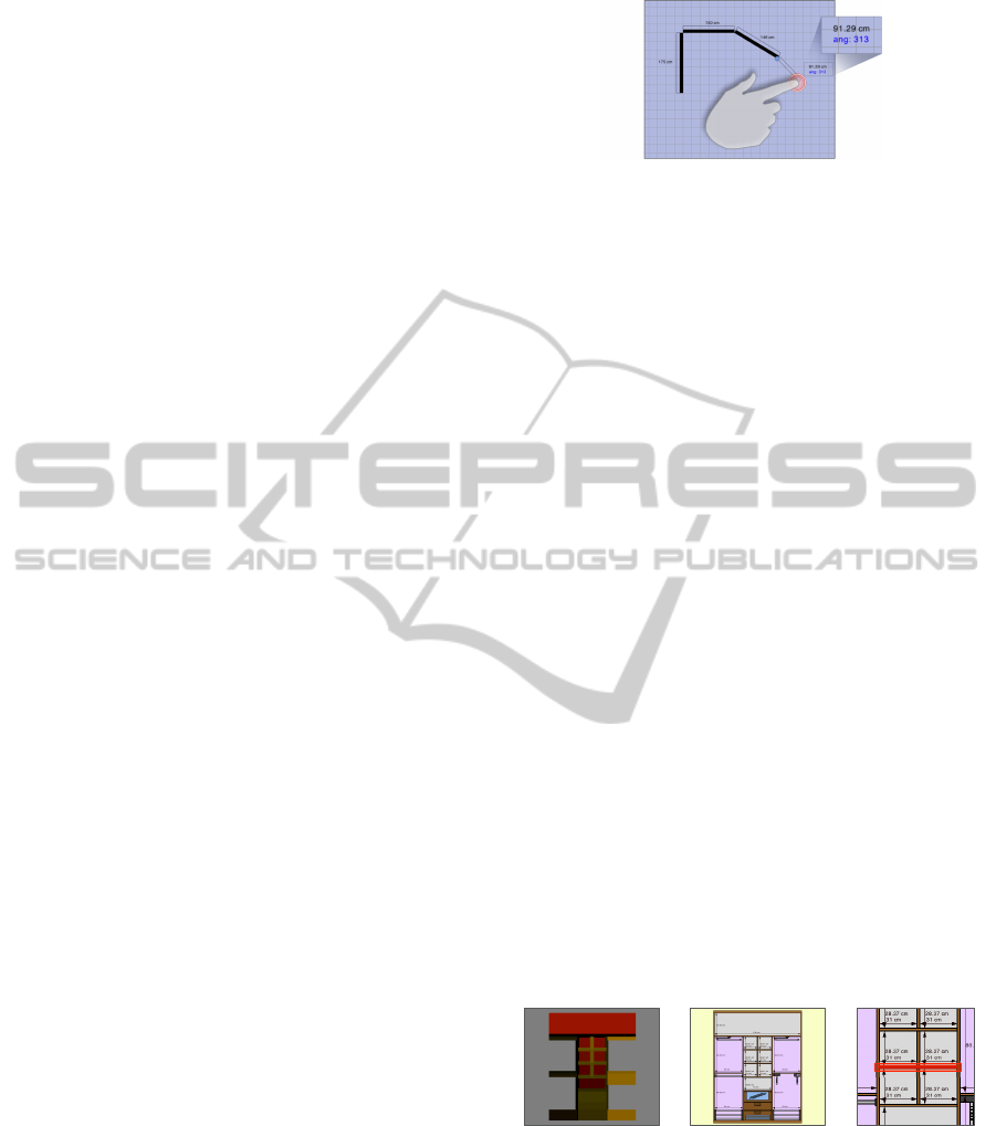
fundamental for its successful completion. Figure 7
shows an example of the use of this technique to sup-
port the creation of walls.
After creating the first end of the wall, the system
provides a real-time preview of it as the user drags his
Figure 7: Using the additional viewport to enhance the wall
creation process.
finger on the drawing canvas to set the other end. As
shown in Figure 7, the finger itself prevents the indi-
vidual from seeing the exact position of the second
end, causing the loss of an essential reference for the
successful creation of the wall. In order to prevent
this, the additional viewport shows the exact length of
the wall with an accuracy of two decimal places.
The auxiliary display area is shown when one
finger taps anywhere in the drawing canvas and it
is located in a position near the contact point. The
magnitude of displacement between the finger and
the viewport positions is constant. Thanks to this
we avoid changing the user’s visual attention during
the object translation. For its part, the direction and
orientation of the offset vary depending on the finger
position in order to ensure that the viewport is always
shown within the fixed limits of the canvas.
Non-visible expansion of the selectable area of an
object. This mechanism seeks to solve the accuracy
problem without visually change the size of the ob-
jects in the scene. A non-visible rectangular area is
associated to each element of the sketch and acts as
its selectable area: the graphical information of the
area is not displayed on screen, but it is rendered to an
off-screen buffer. Thus, we can increase the on-screen
target size in order to facilitate the selection task while
maintaining a realistic representation of the objects.
!"#
!$#
!%#
Figure 8: Expansion of the selectable area of the different
elements of the closet carcass. (a) shows a representation of
the color information for the corresponding selectable areas.
(b) shows the on-screen displaying of the closet. In (c) we
provide a graphic of how the selectable area expands the
area of a closet shelf.
As shown in Figure 8, there is a clear center align-
ment between each element of the sketch and its cor-
responding selectable area. To expand the selectable
area we assign to it dimensions that exceed the size of
GRAPP2014-InternationalConferenceonComputerGraphicsTheoryandApplications
414

the object itself.
Our selection algorithm is based on the color
picking method, common in OpenGL or DirectX.
To support this algorithm a unique color is assigned
to each selectable area (Figure 8.a). A unique ID,
consisting of the RGB color values of the area,
is associated to the corresponding object. Having
established this relationship, the algorithm is able to
extract the color information of the exact pixel where
the finger contacts with the selection area and then
search the object whose ID matches the RGB data.
Increasing information space by using zoom. The
zoom tool allows the user to adjust the information
space to an appropriate size for selecting on-screen
items comfortably. The implemented algorithm is
based on the use of the standard pinch multi-touch
gestures to make the zoom mode activation fully
transparent to the user. This mode is automatically
activated when the individual begins to drag two fin-
gers describing a pinch-in or pinch-out gesture. The
amount of zoom is calculated in real time from the
distance between those two fingers.
5.4 Minimizing and Facilitating Mode
Switching
Generally, mode switching means a change of con-
text that usually involves interrupting the workflow.
In this respect, it will be possible to streamline the
user’s tasks to the extent we are able to minimize the
need to change between modes.
However, the wide range of features and func-
tions that software design tools usually provide, sig-
nificantly hinders this minimization: when the user
interacts with this kind of tools, it is usual that he in-
tentionally selects the corresponding dedicated con-
trol in order to activate the new mode.
Our approach is based on two strategies that seek
to simplify the alternation between them. These
strategies consist of (i) providing user transparent ac-
cess to frequently used tools and (ii) using multi-
touch gestures for switching between the different
modes associated with these tools.
Sketch Arm provides fully transparent access to
selection, translation and, as we have already seen,
zoom tools:
• The selection mode is automatically enabled
when the user ends any operation and disables its
corresponding control.
• When the selection mode is enabled and an ob-
ject is selected, a drag gesture with one finger
enables the translation mode, as previously indi-
cated. When the user lifts the finger from the
touchscreen, the translation mode ends and the se-
lection mode is automatically enabled again.
• Sketch Arm allows switching to zoom mode at any
moment, regardless of the current mode, when the
user performs a pinch gesture. As soon as the user
lifts one finger, the zoom mode ends and the ex-
isting context before its activation is recovered.
6 CONCLUSIONS AND FUTURE
RESEARCH
As a result of the work we have done, Sketch Arm
brings closet design to non-professional users by pro-
viding a touch-based experience and a virtually trans-
parent interface that allows them to interact with the
system in a natural manner. A user interface designed
in this way, facilitates learning through the design
process and generates on the individual the sensation
of mastering the tools after little training. Bellow we
summarize the main contributions of our work:
• Graphic user interface with an attractive and min-
imalist design.
• Design of control elements suitable for touch in-
teraction.
• Touch-based action templates for a natural inter-
action in sketching tasks.
• A new approach to object scaling in touch-based
systems called indirect scaling.
• The design and implementation of specific mech-
anisms to avoid occlusion and accuracy problems,
caused by the use of a finger as a pointing device.
Taking the Shift technique as a reference, we use
an additional viewport for displaying relevant in-
formation in certain operations; we introduce an
innovative technique that seeks to solve the ac-
curacy problem by associating to each on-screen
object a non-visible larger selectable area; and, fi-
nally, we simplify the switch between modes by
using multi-touch gestures.
For further work, it will be necessary to conduct
empirical studies in order to evaluate the goodness
of the proposed interaction system in terms of the
performance and error rate obtained by professional
and novice users when performing certain tasks in
the design process. It will also be desirable to make
a comparative study to determine which kind of
system, touch or desktop, is the most suitable for
each considered user profile based on the individuals’
performance and their subjective opinion.
TowardsaNaturalInteractionforRapidPrototypingofParametricClosets
415

ACKNOWLEDGEMENTS
This work was supported by project 10DPI305002PR
of Xunta de Galicia and by project ITC-20133062 co-
funded by the Ministry of Economy and Competitive-
ness through CDTI within the Innterconecta FEDER
Programme, Galicia 2013 Call.
REFERENCES
Albinsson, P.-A. and Zhai, S. (2003). High precision touch
screen interaction. In Proceedings of the SIGCHI
Conference on Human Factors in Computing Systems,
CHI ’03, pages 105–112. ACM.
Bae, S.-H., Balakrishnan, R., and Singh, K. (2008). ILoveS-
ketch: as-natural-as-possible sketching system for
creating 3d curve models. In Proceedings of the 21st
annual ACM symposium on User interface software
and technology, UIST ’08, pages 151–160. ACM.
Bederson, B. B. (2000). Fisheye menus. In Proceedings
of the 13th annual ACM symposium on User interface
software and technology, UIST ’00, pages 217–225.
ACM.
Benko, H., Wilson, A. D., and Baudisch, P. (2006). Pre-
cise selection techniques for multi-touch screens. In
Proceedings of the SIGCHI Conference on Human
Factors in Computing Systems, CHI ’06, pages 1263–
1272. ACM.
Dandekar, K., Raju, B. I., and Srinivasan, M. A. (2003).
3-d finite-element models of human and monkey fin-
gertips to investigate the mechanics of tactile sense.
Journal of biomechanical engineering, 125(5):682–
691. PMID: 14618927.
Dietz, P. and Leigh, D. (2001). DiamondTouch: a multi-
user touch technology. In Proceedings of the 14th an-
nual ACM symposium on User interface software and
technology, UIST ’01, pages 219–226. ACM.
Hall, A. D., Cunningham, J. B., Roache, R. P., and Cox,
J. W. (1988). Factors affecting performance using
touch-entry systems: Tactual recognition fields and
system accuracy. Journal of Applied Psychology,
73(4):711–720.
Han, J. Y. (2005). Low-cost multi-touch sensing through
frustrated total internal reflection. In Proceedings of
the 18th annual ACM symposium on User interface
software and technology, UIST ’05, pages 115–118.
ACM.
Hornecker, E. (2008). ”I don’t understand it either, but it
is cool”; - visitor interactions with a multi-touch table
in a museum. In 3rd IEEE International Workshop
on Horizontal Interactive Human Computer Systems,
2008. TABLETOP 2008, pages 113–120.
Kabbash, P. and Buxton, W. A. S. (1995). The ”prince”
technique: Fitts’ law and selection using area cursors.
In Proceedings of the SIGCHI Conference on Human
Factors in Computing Systems, CHI ’95, pages 273–
279. ACM Press/Addison-Wesley Publishing Co.
Lewis, J. R., Potosnak, K. M., and Magyar, R. L. (1997).
Chapter 54 - keys and keyboards. In Marting, G. H.,
Thomas, K. L., Prasad V. PrabhuA2 Marting G. He-
lander, T. K. L., and Prasad, V. P., editors, Hand-
book of Human-Computer Interaction (Second Edi-
tion), pages 1285–1315. North-Holland, Amsterdam.
Lundstrom, C., Rydell, T., Forsell, C., Persson, A., and Yn-
nerman, A. (2011). Multi-touch table system for med-
ical visualization: Application to orthopedic surgery
planning. IEEE Transactions on Visualization and
Computer Graphics, 17(12):1775–1784.
Pinhanez, C., Kjeldsen, R., Tang, L., Levas, A., Podlaseck,
M., Sukaviriya, N., and Pingali, G. (2003). Creat-
ing touch-screens anywhere with interactive projected
displays. In Proceedings of the eleventh ACM interna-
tional conference on Multimedia, MULTIMEDIA ’03,
pages 460–461. ACM.
Potter, R. L., Weldon, L. J., and Shneiderman, B. (1988).
Improving the accuracy of touch screens: an experi-
mental evaluation of three strategies. In Proceedings
of the SIGCHI Conference on Human Factors in Com-
puting Systems, CHI ’88, pages 27–32. ACM.
Quevedo-Fern
´
andez, J. and Martens, J. B. (2012). Demon-
strating idAnimate: a multi-touch system for sketch-
ing and rapidly manipulating animations. In Pro-
ceedings of the 7th Nordic Conference on Human-
Computer Interaction: Making Sense Through De-
sign, NordiCHI ’12, pages 767–768. ACM.
Rekimoto, J. (2002). SmartSkin: an infrastructure for free-
hand manipulation on interactive surfaces. In Pro-
ceedings of the SIGCHI Conference on Human Fac-
tors in Computing Systems, CHI ’02, pages 113–120.
ACM.
Rodr
´
ıguez, I., G
´
omez-Meire, S., Barreiro, E., Rodeiro, J.,
and Campos, C. (2013). Sketch arm, custom clos-
ets rapid prototyping system. Procedia Computer Sci-
ence, 18(0):986–995.
Sears, A. and Shneiderman, B. (1991). High precision
touchscreens: design strategies and comparisons with
a mouse. Int. J. Man-Mach. Stud., 34(4):593–613.
Vogel, D. and Baudisch, P. (2007). Shift: a technique for
operating pen-based interfaces using touch. In Pro-
ceedings of the SIGCHI Conference on Human Fac-
tors in Computing Systems, CHI ’07, pages 657–666.
ACM.
Wang, F. and Ren, X. (2009). Empirical evaluation for fin-
ger input properties in multi-touch interaction. In Pro-
ceedings of the SIGCHI Conference on Human Fac-
tors in Computing Systems, CHI ’09, pages 1063–
1072. ACM.
Worden, A., Walker, N., Bharat, K., and Hudson, S. (1997).
Making computers easier for older adults to use: area
cursors and sticky icons. In Proceedings of the ACM
SIGCHI Conference on Human factors in computing
systems, CHI ’97, pages 266–271. ACM.
Zhai, S., Hunter, M., and Smith, B. A. (2000). The metropo-
lis keyboard - an exploration of quantitative tech-
niques for virtual keyboard design. In Proceedings
of the 13th annual ACM symposium on User interface
software and technology, UIST ’00, pages 119–128.
ACM.
GRAPP2014-InternationalConferenceonComputerGraphicsTheoryandApplications
416
